In the circuit shown below, V should be:
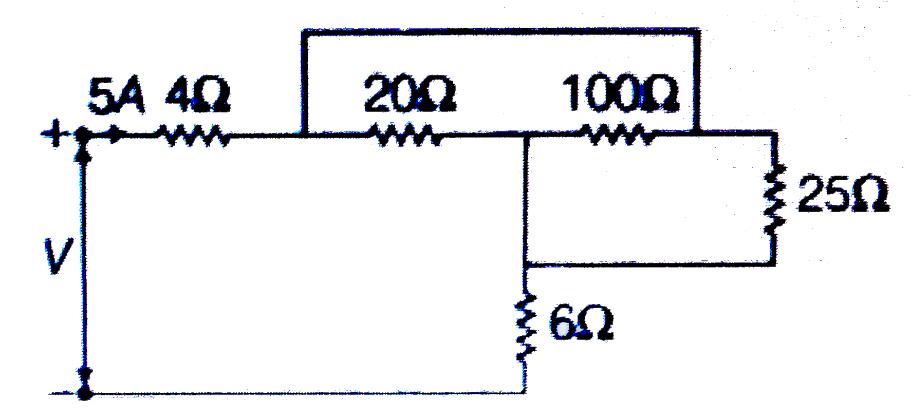
50V
100V
75V
25V
The correct Answer is:B
Step by step video & image solution for In the circuit shown below, V should be: by Physics experts to help you in doubts & scoring excellent marks in Class 11 exams.
Updated on:21/07/2023Topper's Solved these Questions
Similar Questions
For the circuit shown
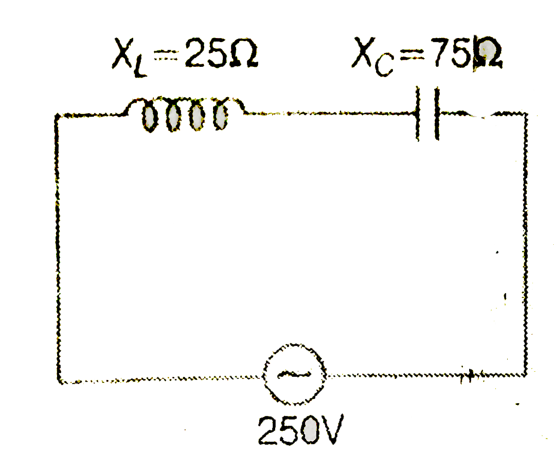
View SolutionIn the circuit shown below, what will be the reading of the voltmeter and ammeter?
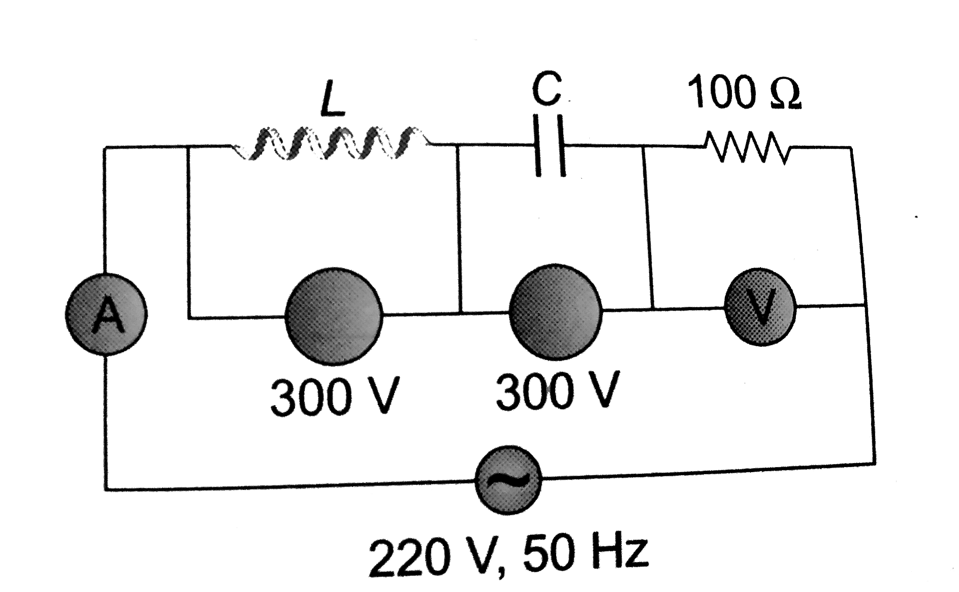
View SolutionA circuit is shown below.
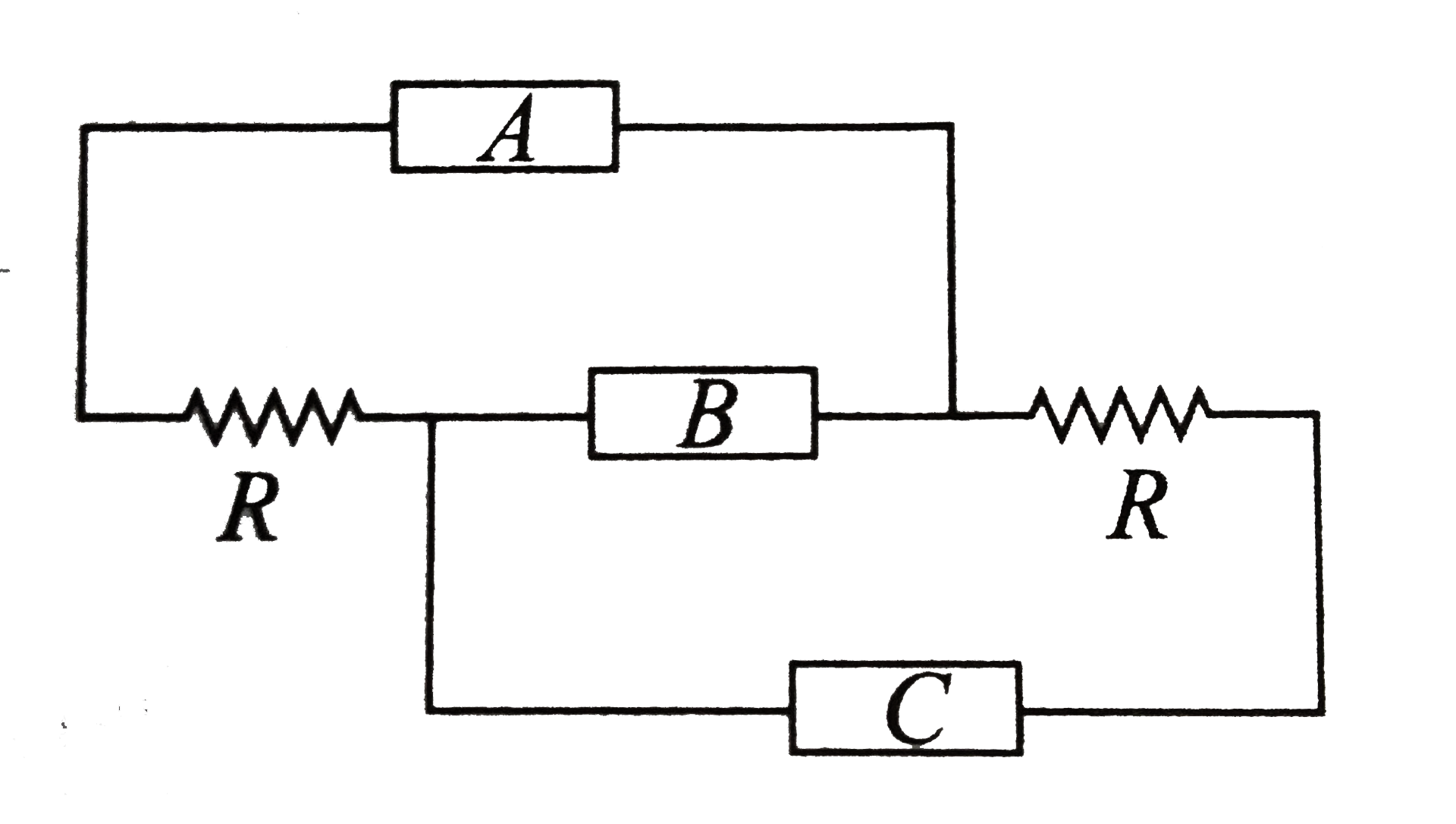
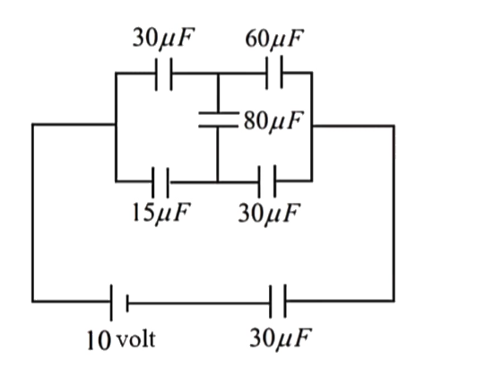
View SolutionIn the circuit shown below, the charge on the 60μF capacitor is
View SolutionIn the circuit shown below, each battery is 5V and has an internal resistance of 0.2 ohm.
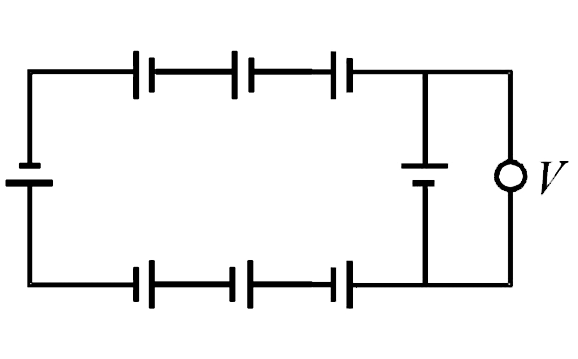
The reading in the ideal voltmeter V is .
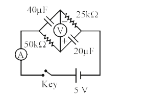
View SolutionIn the circuit shown below, the key is pressed at time t = 0. The correct statement is
View SolutionIn the circuit shown below, E is a battery of emf 6 V and internal resistance 1Ω. Find the reading of the ammeter A. if it has negligible resistance :

View SolutionThe current I in the circuit shown below is
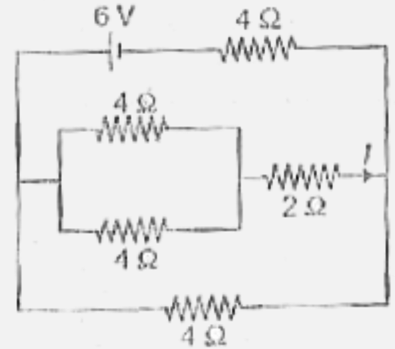
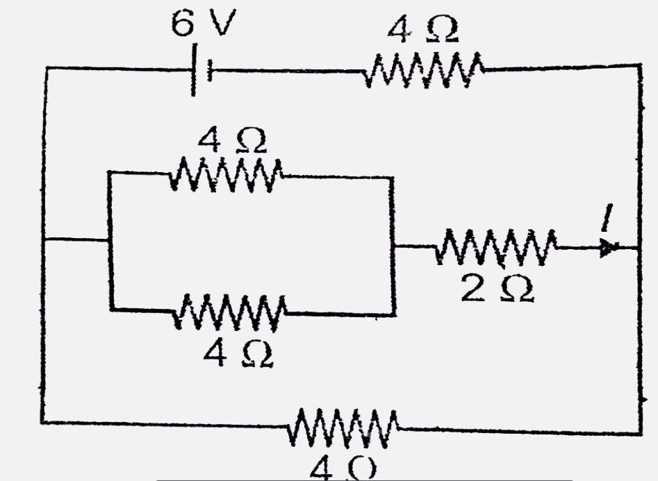
View SolutionThe current l in the circuit shown below is
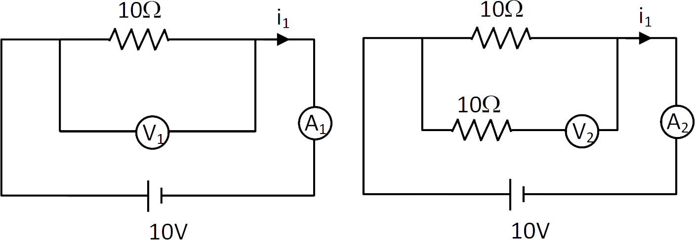
View SolutionIn the circuits shown below, the readings of the voltmeters and the ammeters will be:
View Solution
