In the circuit shown, R1=2Ω,R2=R3=10Ω,R4=20ΩandE=6V. Work out the equivalent resistance of the circuit and the current in each resistor.
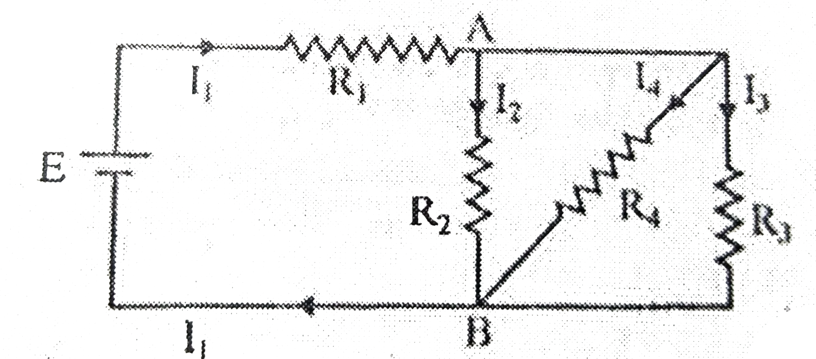
Step by step video & image solution for In the circuit shown, R_1=2 Omega,R_2=R_3=10Omega, R_4=20Omega and E=6V. Work out the equivalent resistance of the circuit and the current in each resistor. by Physics experts to help you in doubts & scoring excellent marks in Class 12 exams.
Updated on:21/07/2023Similar Questions
In the circuit shown, R1=2Ω,R2=R3=10ΩandE=6V. Work out the equivalent resistance of the circuit and the current in each resistor.

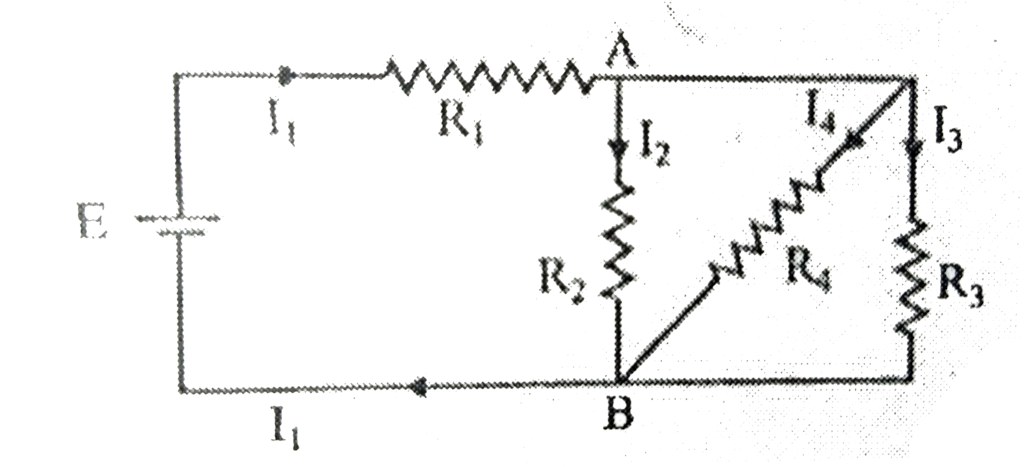
View SolutionIn the circuit shown, R1=4Ω,R2=R3=15Ω,R4=30ΩandE=10V. Caculate the equivalent resistance of te circuit and the current in each resistor.
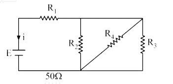
View SolutionIn the given circuit, E=8V,R1=1Ω,R2=R3=R4=5Ω.The current through the resistance R4 is (in A):
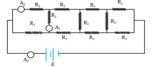
View SolutionIn the given circuit, R1 = 10Ω R2=6Ω and E = 10V, then correct statement is
View Solution(a) Resistors given as R1,R2andR3 are connected in series to a battery V. Draw the circuit diagram showing the arrangement. Derive an expression for the equivalent resistance of the combination.
(b) If R1=10Ω,R2=20ΩandR3=30Ω, calculate the effective resistance when they are connected in series to a battery of 6 V. Also find the current flowing in the circuit.
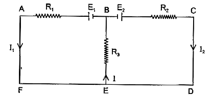
View SolutionIn the circuit shown below, E1=17V,E2=21V,R1=2Ω,R2=3ΩandR3=5Ω. Using Kirchhoff.s laws, find the currents flowing through the resistors R1,R2 and R3. (Internal resistance of each of the batteries is negligible.)
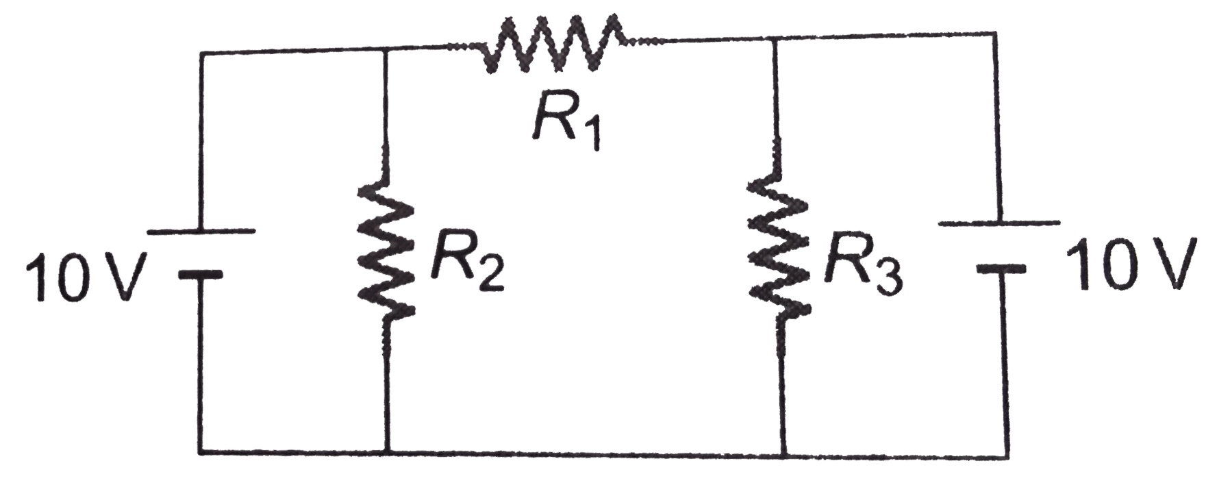
View SolutionIn the curcuit shown in figure R1=R2=R3=10Ω. Find the currents through R1 and R2
View SolutionIn the circuit shown in figure

E1=10V,E2=4V,r1=r2=1Ω and R=2Ω.
Find the potential difference across battery 1 and battery 2.
View SolutionIn the circuit shown in figure

E1=10V,E2=4V,r1=r2=1Ω and R=2Ω.
Find the potential difference across battery 1 and battery 2.
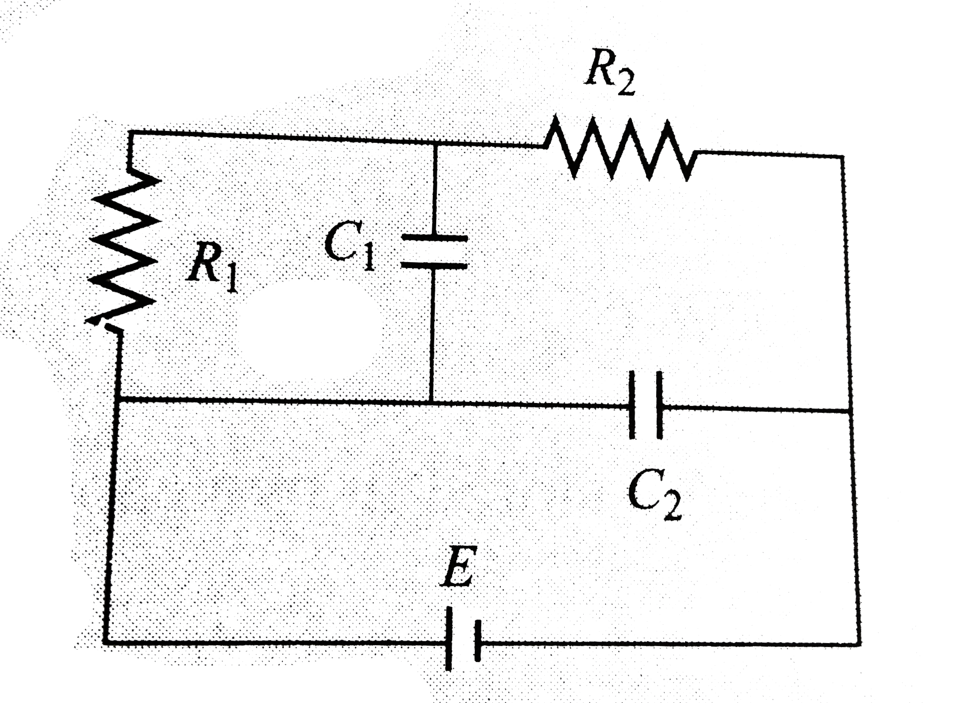
View SolutionIn the circuit shown in fig. R1=10Ω,R2=5Ω,C1=1μF,C2=2μF, and E =6V. Calculate the charge on each capactor in the stedy state.
View Solution
