In the circuit shown in figure
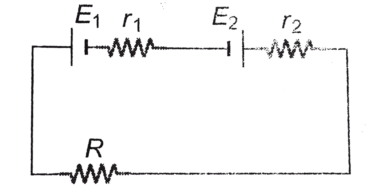
E1=10V,E2=4V,r1=r2=1Ω and R=2Ω.
Find the potential difference across battery 1 and battery 2.
Step by step video & image solution for In the circuit shown in figure E_1=10 V, E_2=4V, r_1=r_2=1Omega and R=2Omega. Find the potential difference across battery 1 and battery 2. by Physics experts to help you in doubts & scoring excellent marks in Class 12 exams.
Updated on:21/07/2023Topper's Solved these Questions
- CURRENT ELECTRICITYBOOK - DC PANDEY ENGLISHCHAPTER - CURRENT ELECTRICITYEXERCISE - Check point
70 Videos
- CURRENT ELECTRICITYBOOK - DC PANDEY ENGLISHCHAPTER - CURRENT ELECTRICITYEXERCISE - Taking it together
142 Videos
- CURRENT ELECTRICITYBOOK - DC PANDEY ENGLISHCHAPTER - CURRENT ELECTRICITYEXERCISE - Level 2 Subjective
13 Videos
- COMMUNICATION SYSTEMBOOK - DC PANDEY ENGLISHCHAPTER - COMMUNICATION SYSTEMEXERCISE - Subjective
11 Videos
- ELECTROMAGNETIC INDUCTIONBOOK - DC PANDEY ENGLISHCHAPTER - ELECTROMAGNETIC INDUCTIONEXERCISE - Medical entrances gallery
25 Videos
Similar Questions
In the circuit in figure E1=3V,E2=2V,E3=1V and R=r1=r2=r3=1Ω
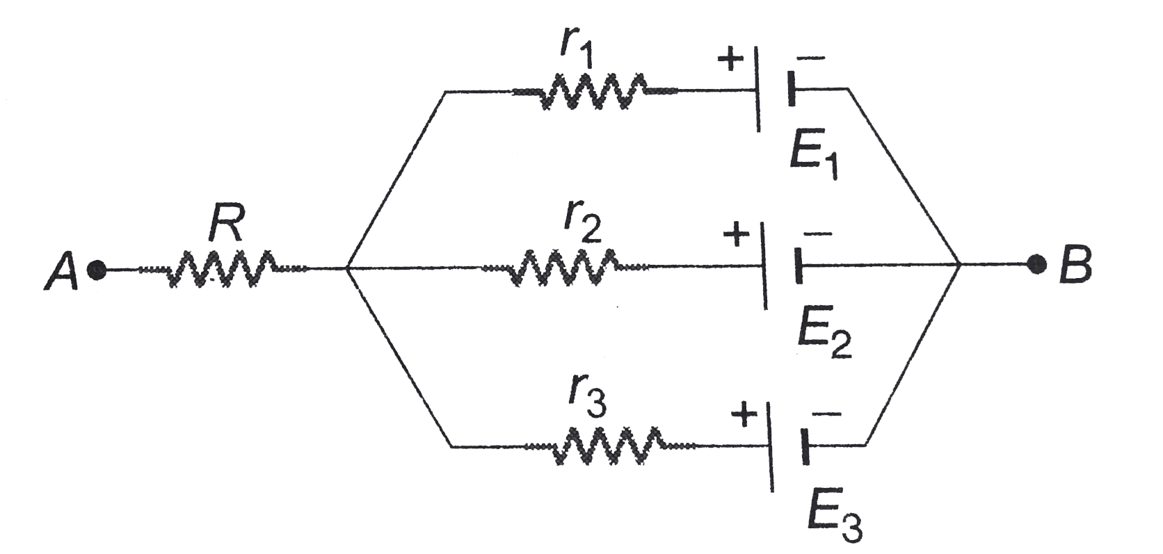
Find the potential differece between the points A and B and the currents through each branch.
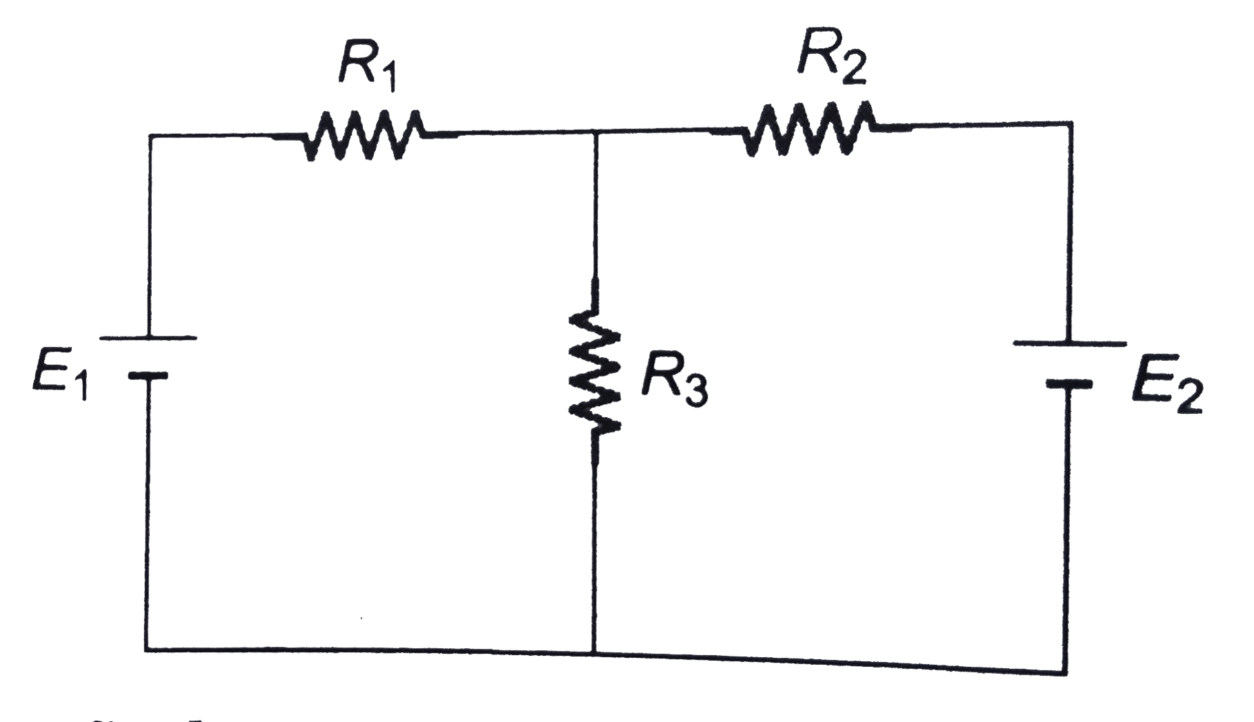
View SolutionIn the circuit shown in figure E1=7V,E2=1V,R1=2Ω,R2=2Ω and R3=3Ω respectively. Find the power supplied by the two batteries.
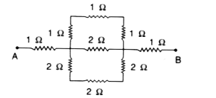
View SolutionCalculate the effective resistance between the points A and B in the circuit shown in Fig.
View Solution(a) Find the equivalent resistance between A and B of the network extending off to the infinity shown in the figure .
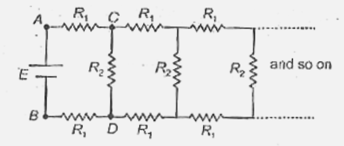
(b) If E=12V,R1=1ΩandR2=4Ω. Find the current in R2 nearest of the battery .
View SolutionIn the circuit shown in figure E1,E2=20V,R1=R2=10kΩ and C=1μF. Find the current through R1,R2 and C when
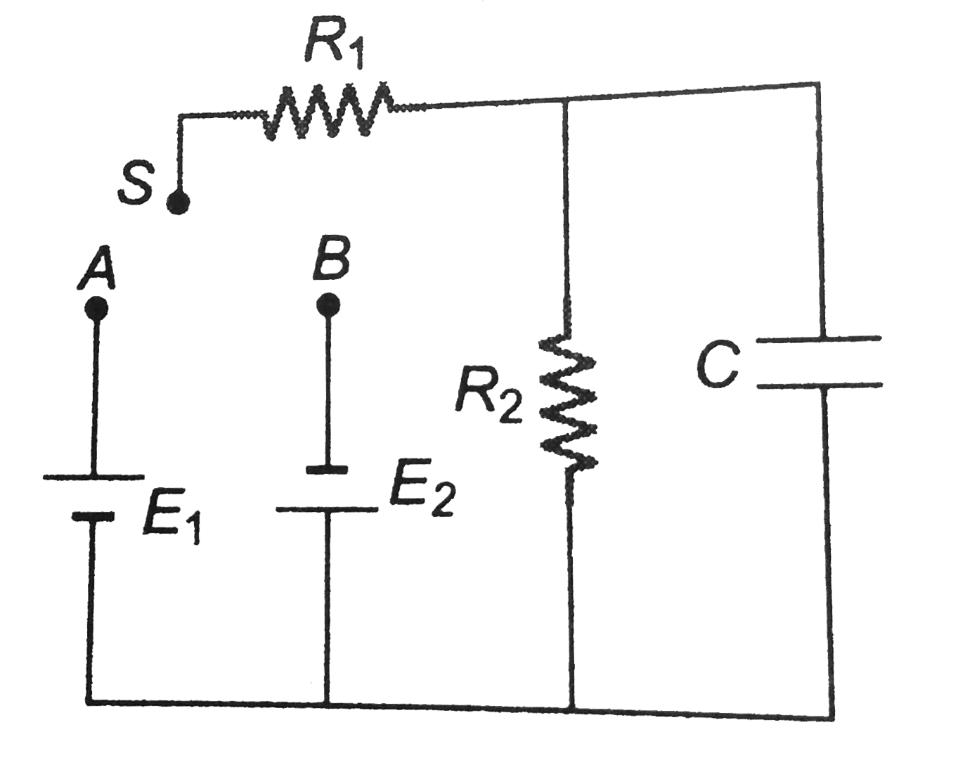
(a) S has been kept connected to A for a long time.
(b) The switch is suddenly shifted to B.
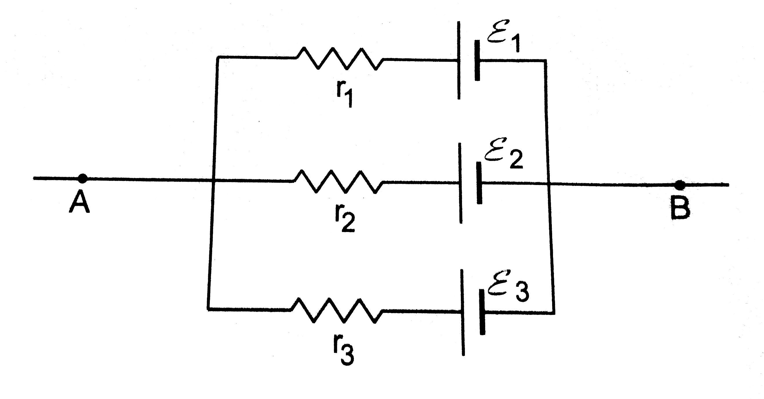
View SolutionIn the circuit shown in figure ,(ε)1=3V,(ε)2=2V,(ε)3=1Vandr1=r2=r3=1(Ω).Find the potential difference between the points A and B and the current through each branch.
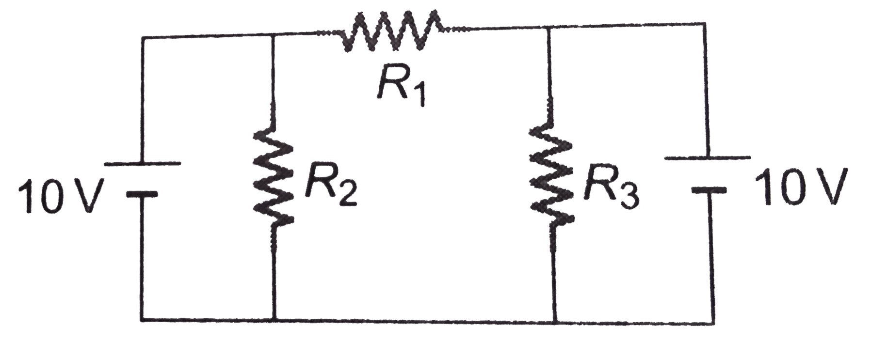
View SolutionIn the curcuit shown in figure R1=R2=R3=10Ω. Find the currents through R1 and R2
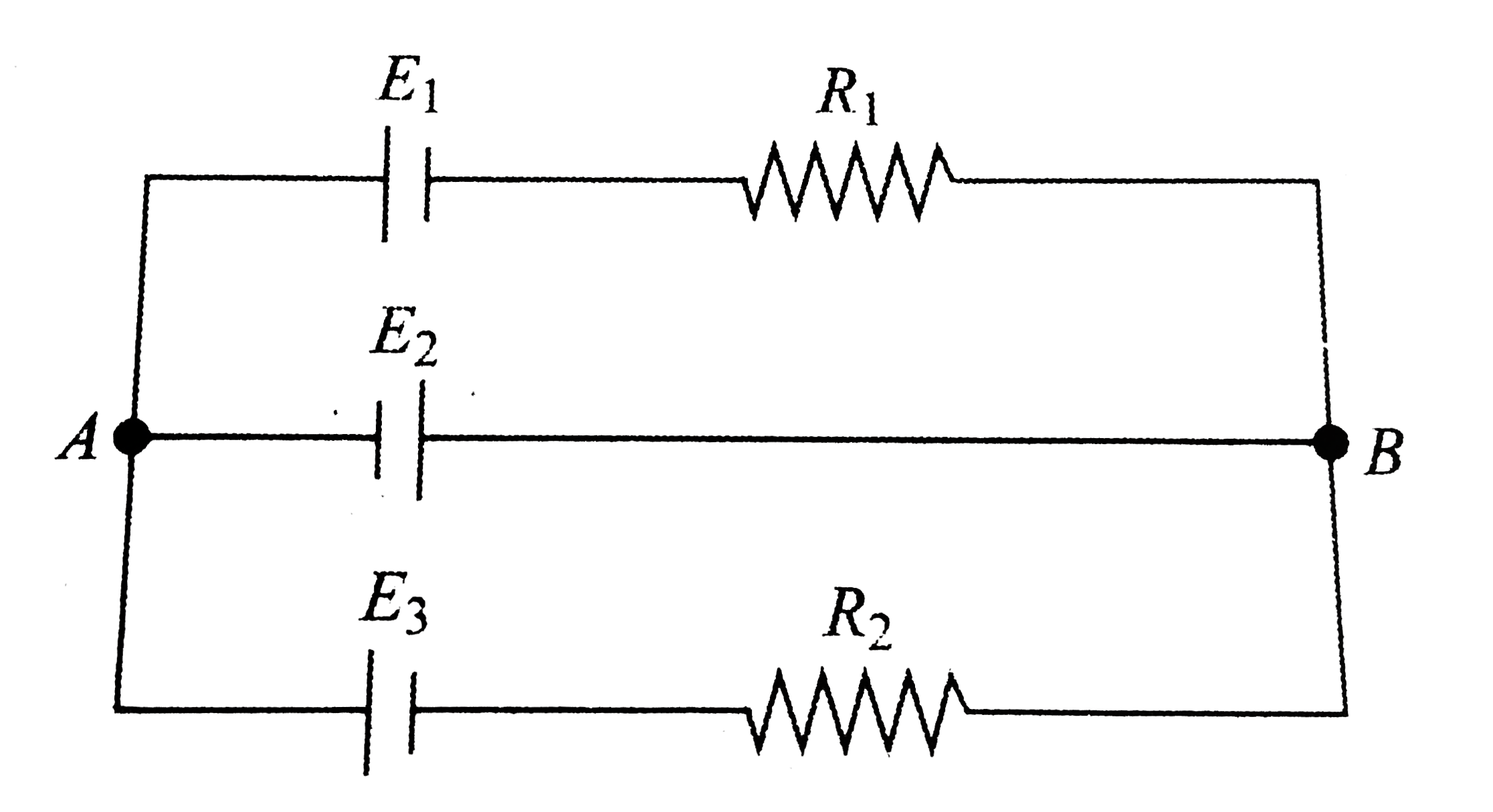
View SolutionIn the circuit shown in fig. 5.265, E1=E2=E3=2V and R1=R2=4Ω. The current flowing between points A and B through battery E2 is
View SolutionIn the circuit shown in figure ammeter and voltmeter are ideal. If E=4V,R=9Ω and r=1Ω then readings of ammeter and voltmeter are
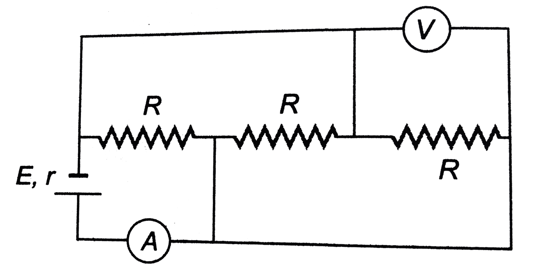
View SolutionIn the circuit shown in figure ammeter and voltmeter are ideal. If E=4V,R=9Ω and r=1Ω then readings of ammeter and voltmeter are

View Solution
