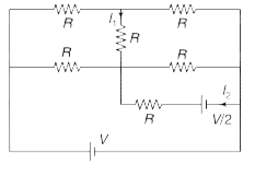
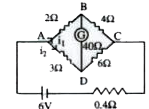
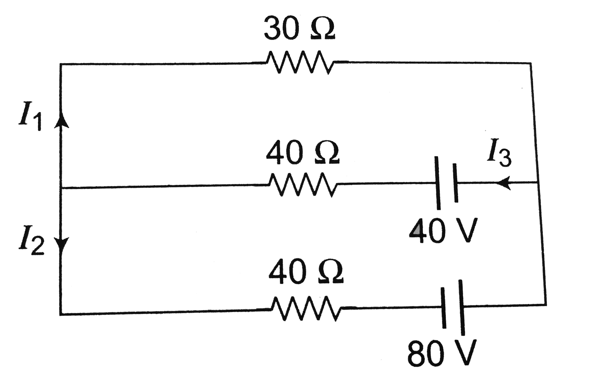
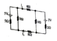
In the circuit shown, the currents and are
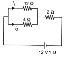
The correct Answer is:B
Resistance,R=
Electric current,
Topper's Solved these Questions
- CURRENT ELECTRICITYBook:MODERN PUBLICATIONChapter:CURRENT ELECTRICITYExercise:MULTIPLE CHOICE QUESTIONS (LEVEL-III)
Explore 13 Videos
- ATOMS, MOLECULES AND NUCLEIBook:MODERN PUBLICATIONChapter:ATOMS, MOLECULES AND NUCLEIExercise:Recent Competitive Questions
Explore 40 Videos
- DESCRIPTION OF MOTION IN ONE DIMENSION Book:MODERN PUBLICATIONChapter:DESCRIPTION OF MOTION IN ONE DIMENSION Exercise:Revision Test
Explore 45 Videos
Similar Questions
Knowledge Check
In the circuit shown, the value of currents I1,I2andI3 are
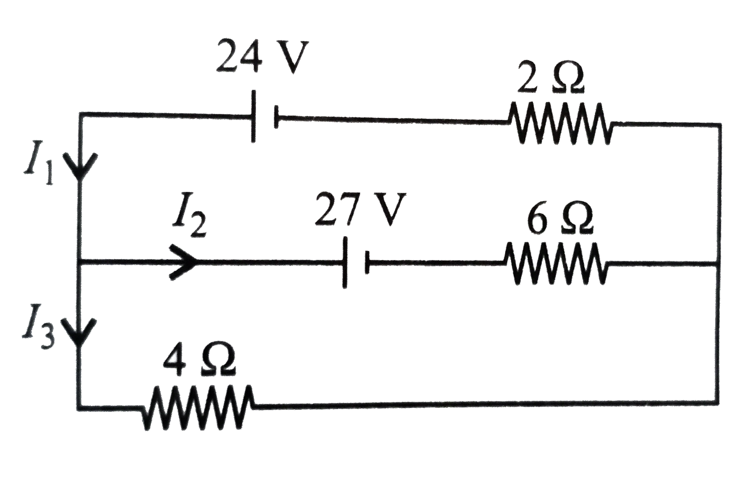 A3A,−3A2A,92AB92A,−32AC5A,4A,−3AD7A,54A,92A
In the circuit shown, the value of currents I1,I2andI3 are
 A3A,−3A2A,92AB92A,−32AC5A,4A,−3AD7A,54A,92A
In the given circuit the current I1 is
 A0.4AB−0.4AC0.8AD−0.8A
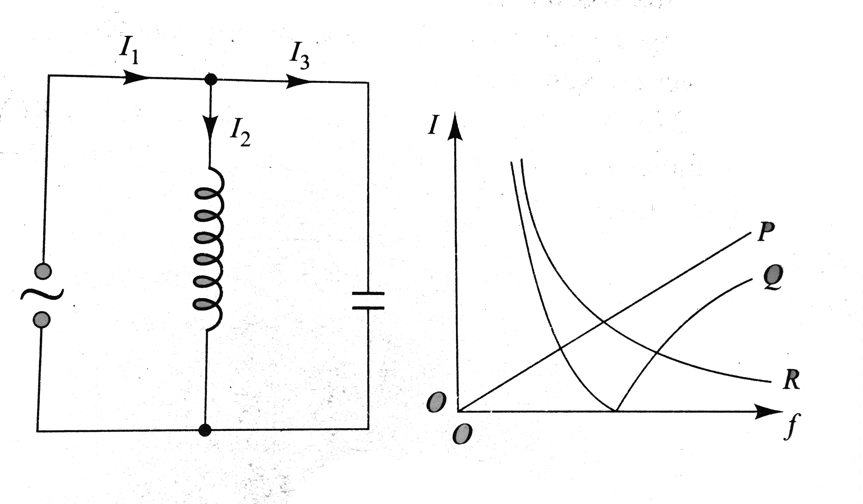
In the circuit shown if fig, the rms currents (I1),(I2) and(I3) are altered by varying the frequency f of the oscillator. The output voltage of the oscillator remains sinusoidal and has a fixed amplitude.
When curves in figure correctly indicate the variation with frequency of the currents (I1),(I2),and(I3).
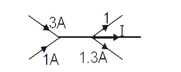
View SolutionFor the circuit shown the value of current I is:-
View SolutionIn the circuit shown if fig, the rims currents (I1),(I2) and(I3) are altered by varying the freqency f of the oscillator. The output voltage of the oscillatro remains sinusoidal and has a fixed amplitude.
When curves in figure correctly indicate the variation with frequency of the currents (I1),(I2),and(I3).

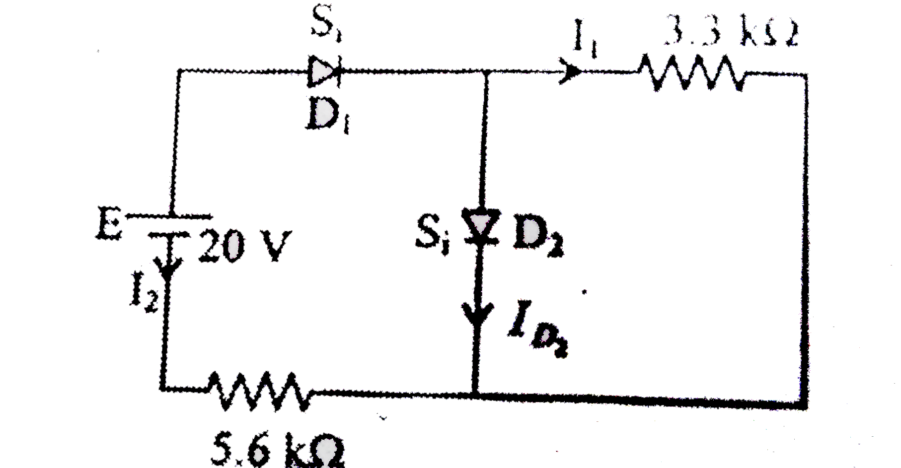
View SolutionIn the circuit shown in figure I1,I2 and ID2 are respectively-
View SolutionIn the circuit shown, the ratio I1I2 is equal to
View Solution

