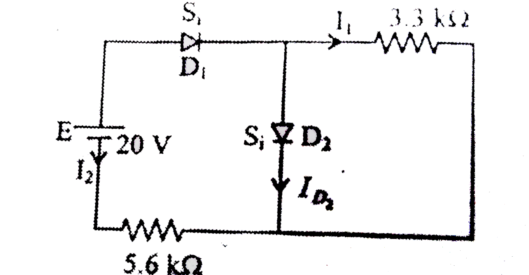
In the circuit shown in figure I1,I2 and ID2 are respectively-
A
0.212MA,3.32mA,3.108mA
B
2.12mA,3.32mA,3.108mA
C
0.212mA,0.332mA,3.108mA
D
None of these
Text Solution
The correct Answer is:A
I1=V1R1=0.212mA
By KVL,
−VT1−VT2−V2+E=0
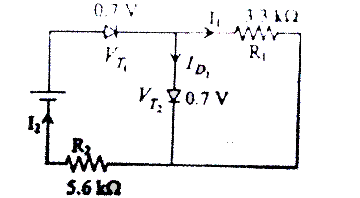
∴V2=20−0.7−0.7=18.6V
I2=V2R2=3.32mA
|
Topper's Solved these Questions
Similar Questions
Knowledge Check
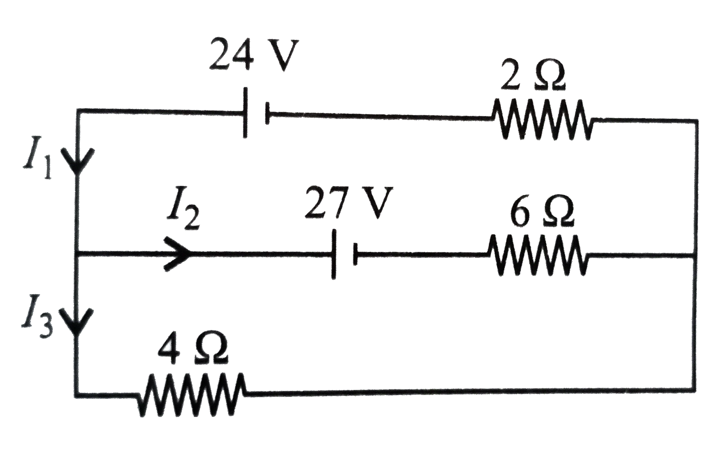
In the circuit shown, the value of currents I1,I2andI3 are
 A3A,−3A2A,92AB92A,−32AC5A,4A,−3AD7A,54A,92A
In the circuit shown, the value of currents I1,I2andI3 are
 A3A,−3A2A,92AB92A,−32AC5A,4A,−3AD7A,54A,92A
In the circuit shown in figure (1), the V0,I1,ID1, and ID3 are respectively.
(A)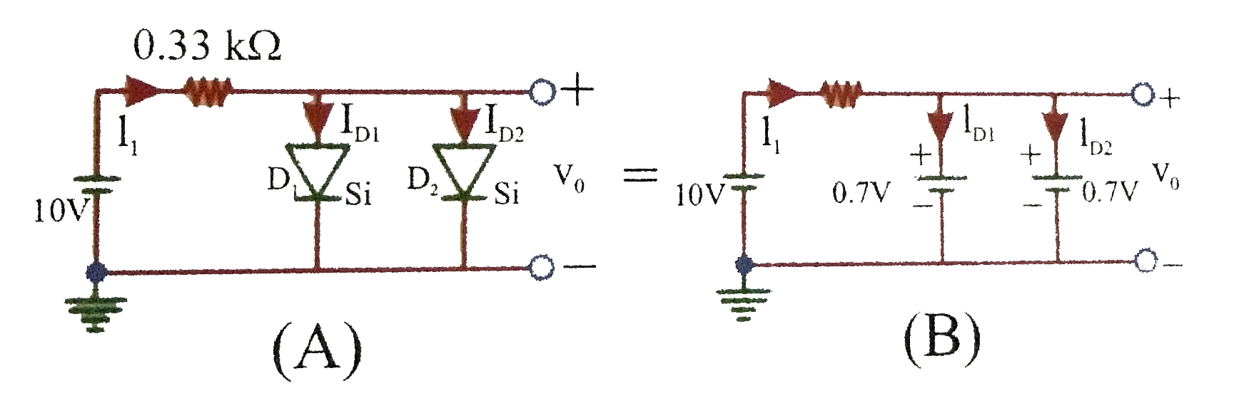 A0.5V,25mA,15mAB0.7V,28mA,14.09mAC0.4V,15mA,20mAD0.3V,15.06mA,20.18mA
In the circuit shown in fig., the value of I1+I2 is
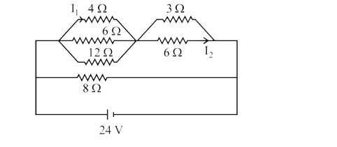
View SolutionIn the circuit shown in fig., the value of I1+I2 is

View SolutionIn the circuit shown in fig., the value of I1+I2 is

View SolutionIn the circuit shown, the currents i1 and i2 are
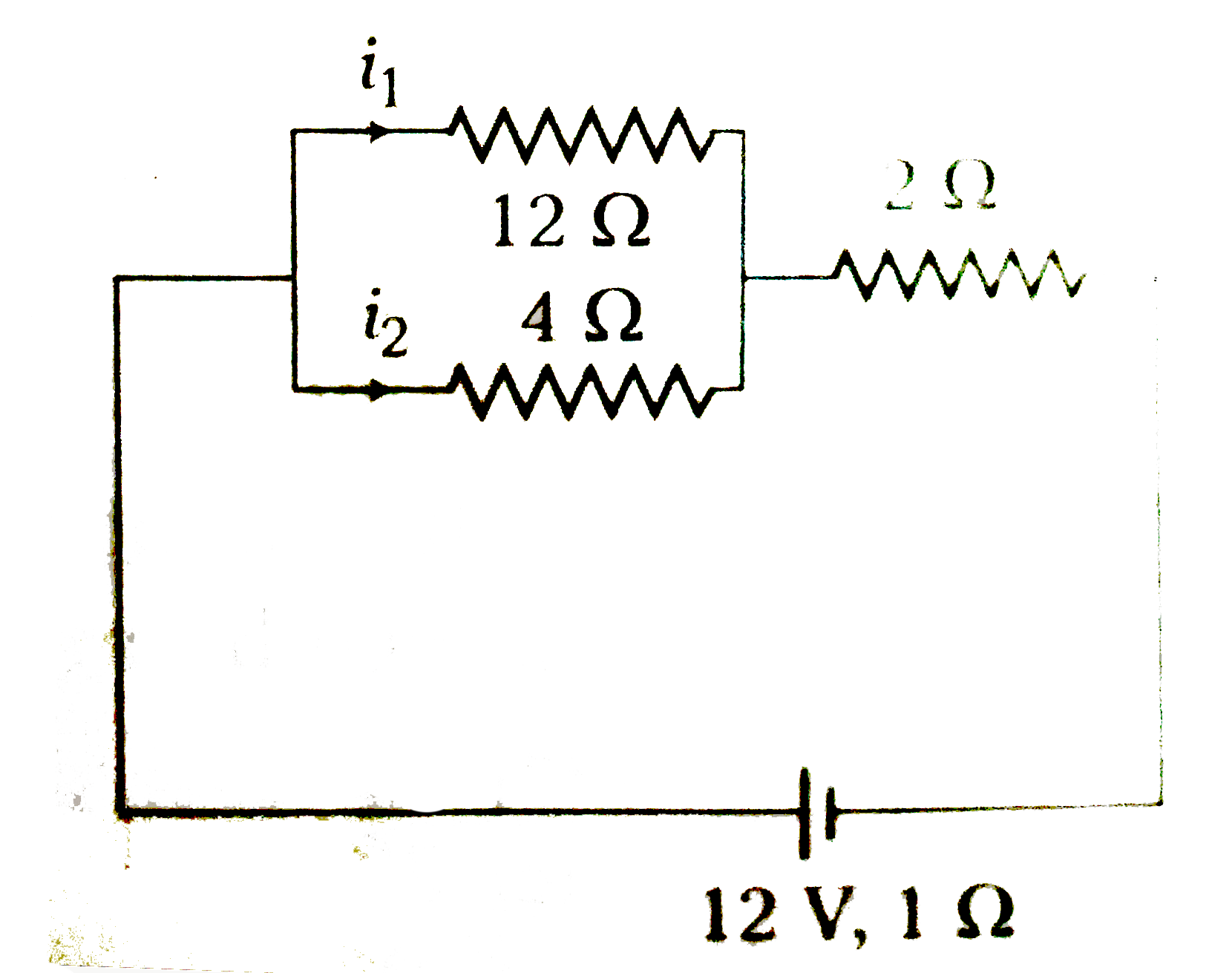
View SolutionA square lamina is as shown in figure. The moment of inertia of the frame about the three axes as shown in figure I1,I2andI3 respectively. Select the correct alternative.
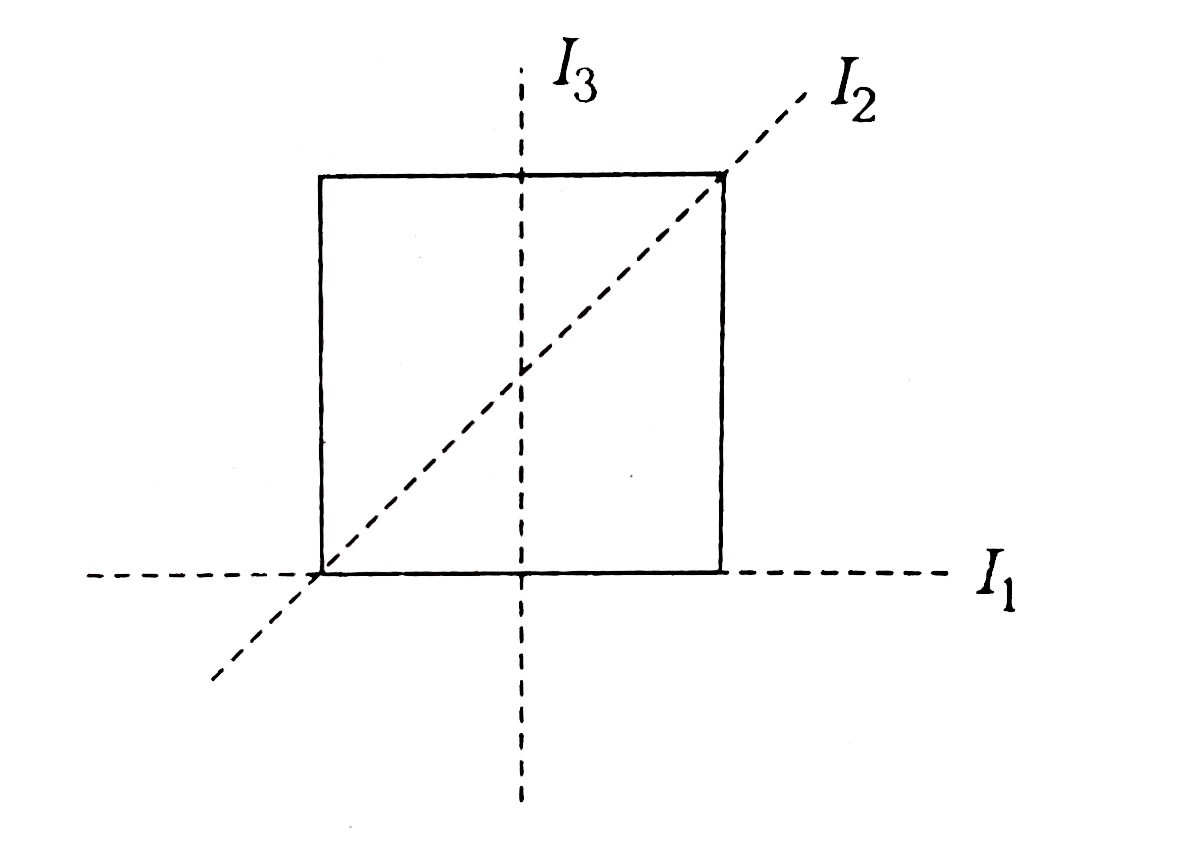
View Solution

