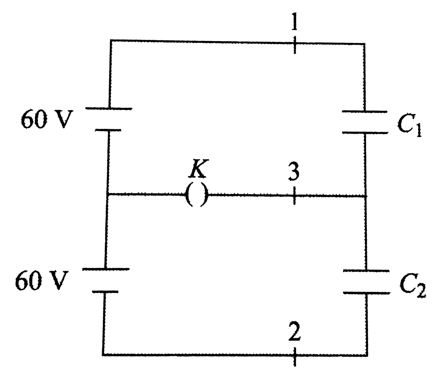
In the circuit shown , the emf of each battery is 60V and C1=2μF and C2=3μF. Find the charges that will flow through the sections 1,2 and 3 after the Key is closed.
 .
.
When the swich is open (Fig)
q0=2ξC1C2C1+C2

and when the swich is closed,
q1=ξC1 and q2=ξC2
Hence, the flow of charge, due to the shortening of swich,
thorugh section 1=q1−q0ξC1[C1−C2C1+C2]=−24μC
through the section 2=−q2−(q0)=ξC2[C1−C2C1+C2]=−36μC
and through the section 3=q2−(q2−q1)−0=ξ(C2−C1)=−60μC
Topper's Solved these Questions
- BOOK - IE IRODOV, LA SENA & SS KROTOVCHAPTER - ELECTRODYNAMICSEXERCISE - Electric Current72videos
ELECTRODYNAMICS
- BOOK - IE IRODOV, LA SENA & SS KROTOVCHAPTER - ELECTRODYNAMICSEXERCISE - Constant Magnetic Fiels - Magnetics69videos
ELECTRODYNAMICS
- BOOK - IE IRODOV, LA SENA & SS KROTOVCHAPTER - ELECTRODYNAMICSEXERCISE - Conductors And Dielectrics In An Electric Field47videos
ELECTRODYNAMICS
- BOOK - IE IRODOV, LA SENA & SS KROTOVCHAPTER - ELECTRICITY AND MAGNETISMEXERCISE - All Questions6videos
ELECTRICITY AND MAGNETISM
- BOOK - IE IRODOV, LA SENA & SS KROTOVCHAPTER - ELECTROMAGNETISMEXERCISE - All Questions24videos
ELECTROMAGNETISM
Similar Questions
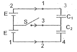
In the circuit shown, the emf of each battery is E. Find the charges that will flow when the switch S is closed, through sections 1, 2 and 3 in the directions indicated by the arrows.
 View Solution
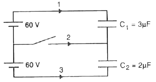
In the circuit shoenin figure 6.17 the emf of each better is 60 V, and the capacitances of the capacitors are C1=3μF and 2μF. Find the charges which will flow after the switch is colosed through the wires 1,2 and 3 n the directions indicated by the arrows.
 View Solution
Knowledge Check
- Question 1 - Select One
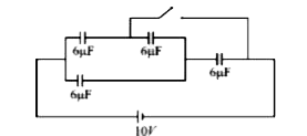
In the circuit shown, find the amount of charge that will flow through the key when it is closed.
 A20μCB40μCC80μCD120μC
 - Question 2 - Select One
In the circuit shown in figure, the ratio of charge on 5μF and 2μF capacitor is
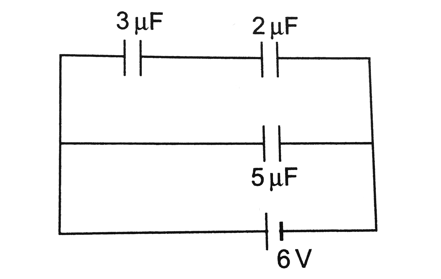 A54B53C38Dnone of these
 - Question 3 - Select One
Capacitor C1=2μFandC2=3μF are connected in series to a battery of emf ε=120V whose midpoint is earthed. The wire connecting the capacitors can be earthed through a key K. Now, key K is closed. Determine the charge flowing through the sections 1, 2, and 3 in the directions indicated in figure
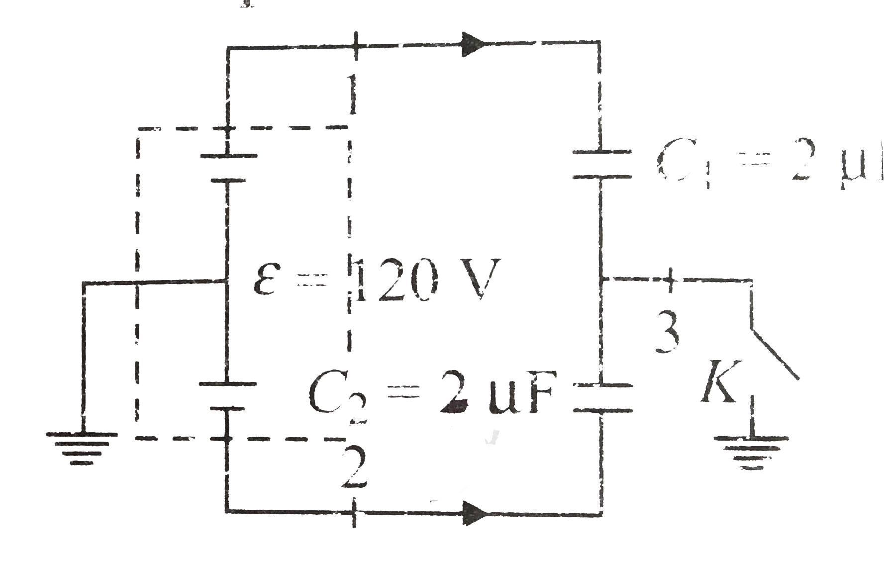
In section 3,A−24μCB−36μCC−60μCD60μC
In the circuit shown the capacitors are C1=15μF,C2=10μFandC3=25μF. Find
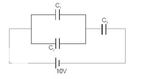
the charge on each capacitor andView SolutionIn the circuit shown the capacitors are C1=15μF,C2=10μFandC3=25μF. Find
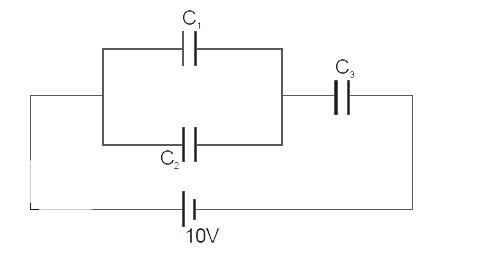
the equivalent capacitance of the circuit.View SolutionIn the circuit shown the capacitors are C1=15μF,C2=10μFandC3=25μF. Find
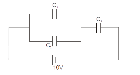
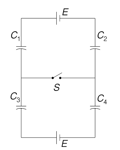
the potential difference across each capacitor.View SolutionIn the circuit shown in Figure E=12V,C1=4μF,C2=2μF,C3=6μFandC4=3μF
Find the heat produced in the circuit after switch S is shorted.
 View Solution
A capacitor of capacitance C1=1.0μF charged up to a voltage V=110V is connected in parallel to the teminals of a circuit consisting of two uncharged capacitors connected in series and possessing the capacitances Cs=2.0μF and Cs=3.0μF. What charge will flow through the connecting wires ?
View Solution

