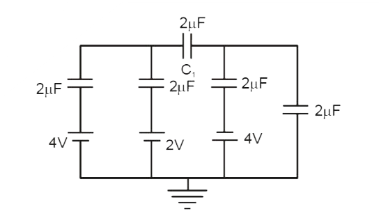
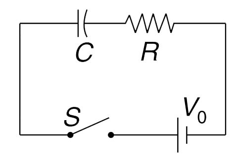
In the circuit shown, the voltage V1 , across capacitor C

is in phase with the source voltage V
leads the source voltage V by 90∘
leads the source voltage V by an angle between 0∘ and 90∘
lags behind the source voltage V by an angle between 0∘ and 90∘
The correct Answer is:D
The phase diagram is as shown in the figure

Topper's Solved these Questions
- ELECTROMAGNETIC INDUCTION AND ALTERNATING CURRENTSBOOK - MTG GUIDECHAPTER - ELECTROMAGNETIC INDUCTION AND ALTERNATING CURRENTSEXERCISE - NEET CAFE TOPICWISE PRATICE QUESTIONS (SERIES LR AND CR CIRCUITS)
1 Videos
- ELECTROMAGNETIC INDUCTION AND ALTERNATING CURRENTSBOOK - MTG GUIDECHAPTER - ELECTROMAGNETIC INDUCTION AND ALTERNATING CURRENTSEXERCISE - NEET CAFE TOPICWISE PRATICE QUESTIONS (POWER IN AC CIRCUITS)
13 Videos
- ELECTROMAGNETIC INDUCTION AND ALTERNATING CURRENTSBOOK - MTG GUIDECHAPTER - ELECTROMAGNETIC INDUCTION AND ALTERNATING CURRENTSEXERCISE - NEET CAFE TOPICWISE PRATICE QUESTIONS (AC CIRCUITS CONTAINING RESISTOR, INDUCTOR OR CAPACITOR)
3 Videos
- DUAL NATURE OF MATTER AND RADIATION BOOK - MTG GUIDECHAPTER - DUAL NATURE OF MATTER AND RADIATION EXERCISE - AIPMT/ NEET MCQs
30 Videos
- ELECTROMAGNETIC WAVESBOOK - MTG GUIDECHAPTER - ELECTROMAGNETIC WAVESEXERCISE - AIPMT/NEET(MCQs)
15 Videos
Similar Questions
Knowledge Check
In the circuit the rms value of voltage across the capacitor C, inductor L and resister R1 are respectively 5√5V, 10 V and 5V. Then the peak voltage a cross R2 is
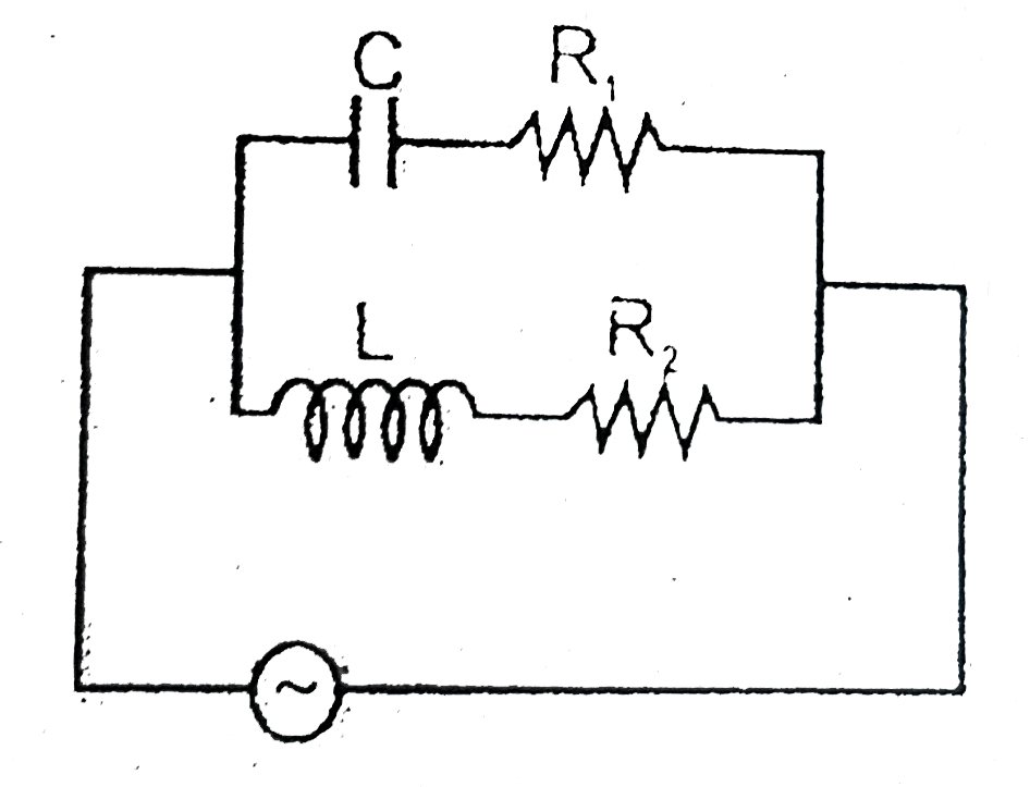 A7VB10VC15VD5√2V
STATEMENT-1: In a series LCR circuit at resonance, the voltage across the capacitor or inductor may be more than the applied voltage.
STATEMENT-2: At resonance in a series LCR circuit, the voltages across inductor and capacitor are out of phase.AStatement-1 is True, Statement-2 is True, Statement-2 is a correct explanation for Statement-1.BStatement-1 is True, Statement-2 is True, Statement-2 is NOT a correct explanation for Statement-1.CStatement-1 is True, Statement-2 is False.DStatement-1 is False, Statement-2 is True.In the circuit shown in figure, the final voltage drop across the capacitor C is :
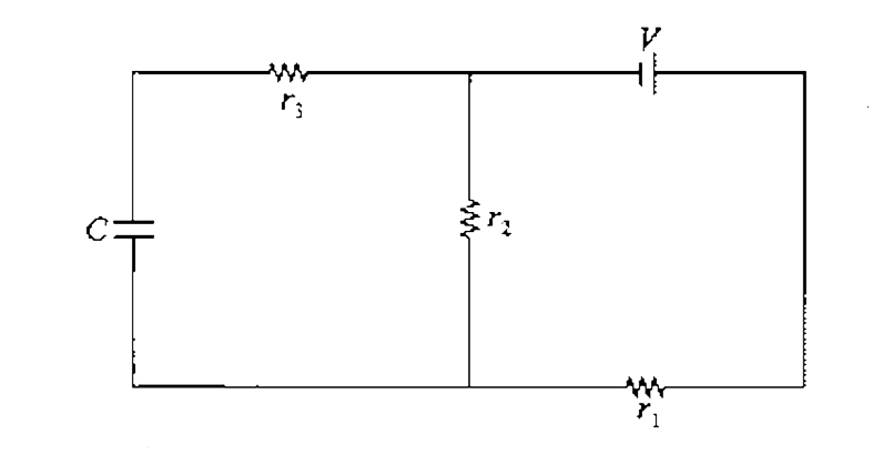 AVr1r1+r2BVr2r1+r2CV(r1+r2)r2DV(r2+r1)r1+r2+r3
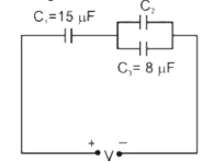
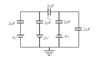 Find voltage across capacitor C1.
View SolutionIn the circuit shown, the rms value of the voltage across the capacitor C, inductor L and resistor R1 are respectively 5√5V,10Vand5V.Thepeakvo<a≥(∈vo<)axrossR_(2) is
'(##CEN_KSR_PHY_JEE_C24_E01_018_Q08##)'
View SolutionIn the LCR circuit shown,if RMS voltages across resistor inductor and capacitor are equal,the RMS value of voltage across resistor will be
View SolutionIn the circuit shown the switch is closed at time t=0. Plot the following graphs:
(i) current (I) in the circuit Vs time (t)
(ii) voltage across the capacitor (VC) Vs ‘t’
(iii) power absorbed by the capacitor Vs ‘t’.
View SolutionIn the circuit shown in the figure, the total charge is 750μC and the voltage across capacitor C2 is 20 V. Then the charge on capacitor C2 is:
View Solution

