In the circuit shown in the figure, the total charge is 750μC and the voltage across capacitor C2 is 20 V. Then the charge on capacitor C2 is:
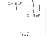
650μC
450μC
590μC
160μC
The correct Answer is:C
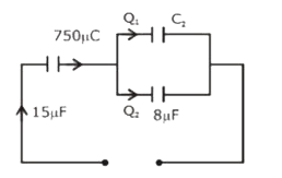
Q2=CV=8μf20=160μC
Q1=750−160=590μC
Topper's Solved these Questions
Similar Questions
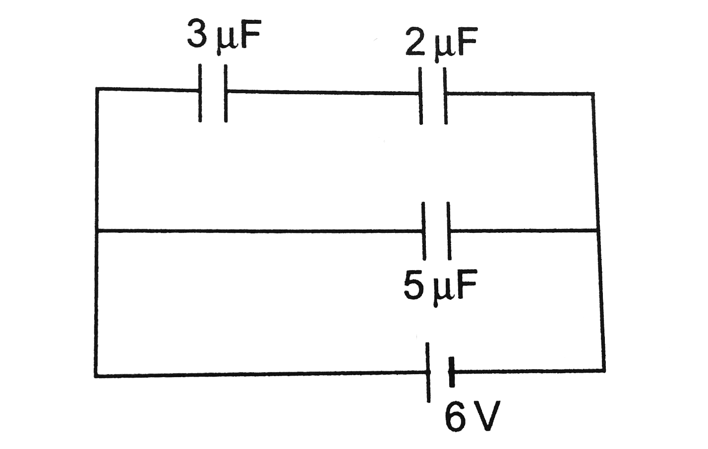
In the circuit shown in figure, the ratio of charge on 5μF and 2μF capacitor is
 View Solution
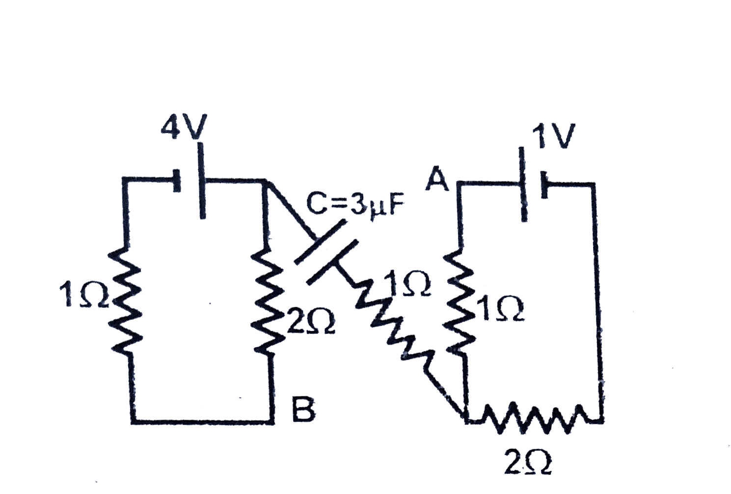
In the circuit shown in the adjacent figure, the batteries are ideal. The charge on the capacitor C is
 View Solution
The circuit is in a steady state.
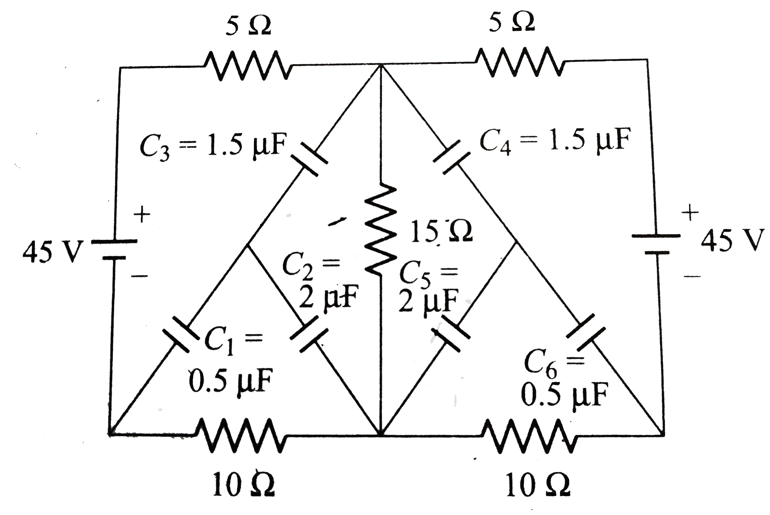
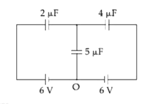
The charge in capacitor C2 isView SolutionIn the circuit shown , charge on the 5μF capacitor is :
 View Solution
In a series C−R circuit shown in figureure, the applied voltage is 10V and the voltage across capacitor is found to8V. The voltage across R, and the phase difference between current and the applied voltage will respectively be
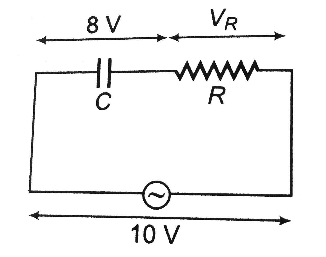 .View Solution
In a series C−R circuit shown in figureure, the applied voltage is 10V and the voltage across capacitor is found to8V. The voltage across R, and the phase difference between current and the applied voltage will respectively be
 .View Solution
The circuit is in a steady state.
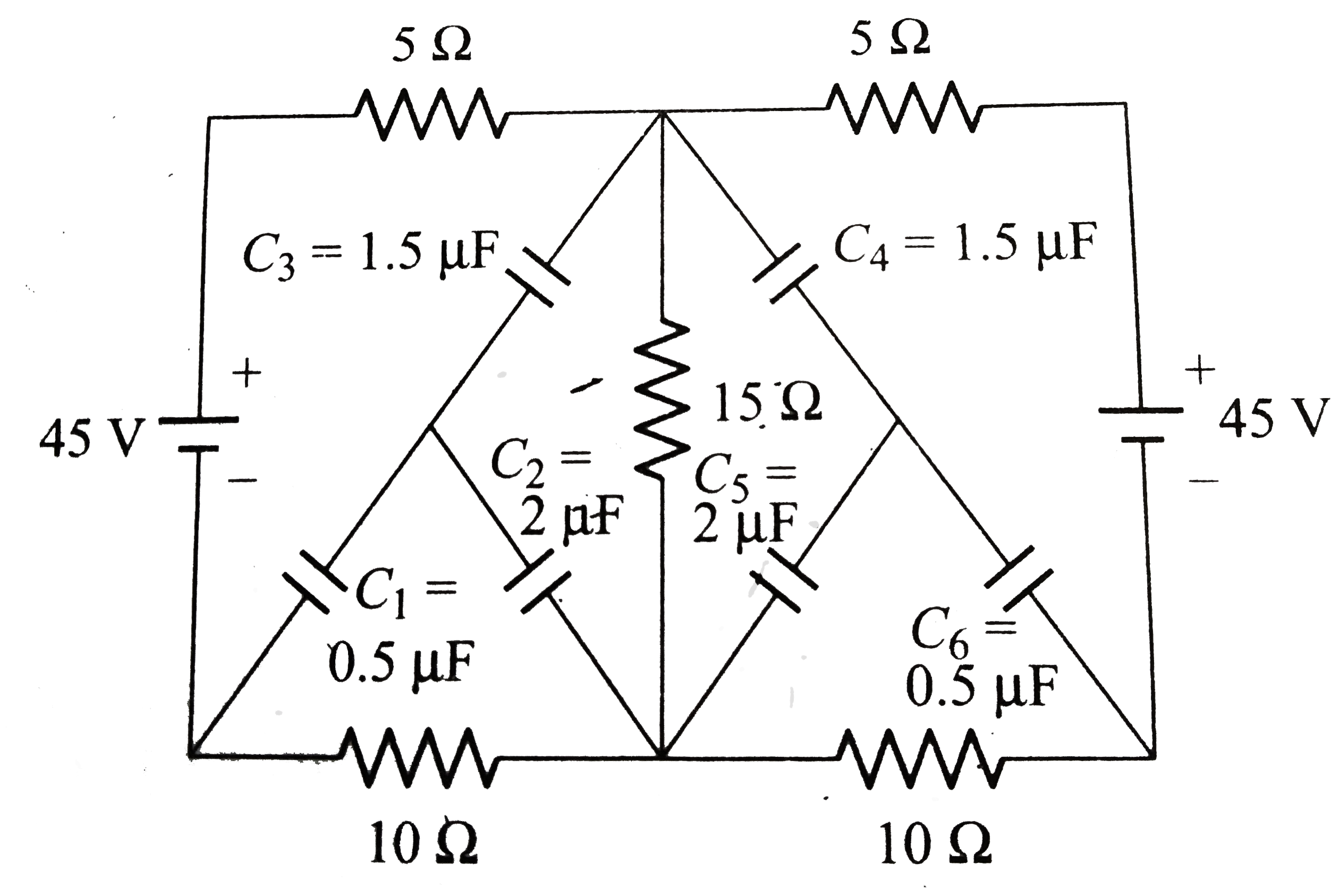
The charge in capacitor C3 isView SolutionThe circuit is in a steady state.
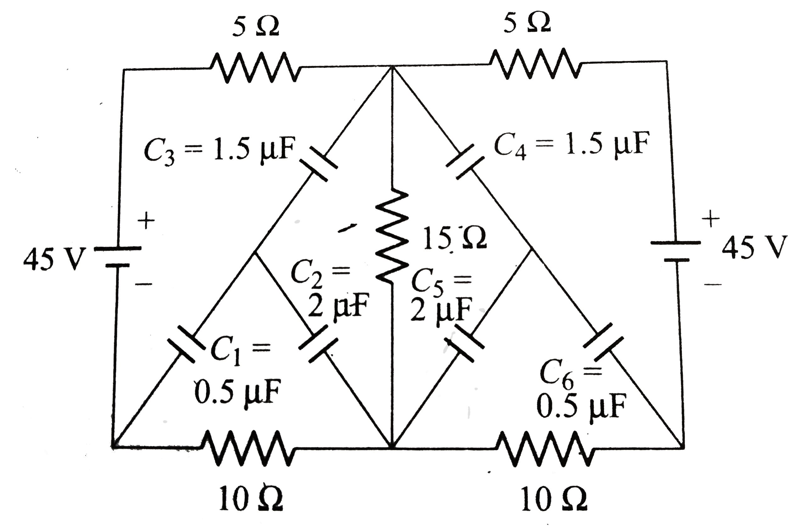
The charge in capacitor C1 isView SolutionIn the circuit shown in figure, the capacitor is charged with a cell of 5V.If the switch is closed at t=0, then at t=12s, charge on the capacitor is
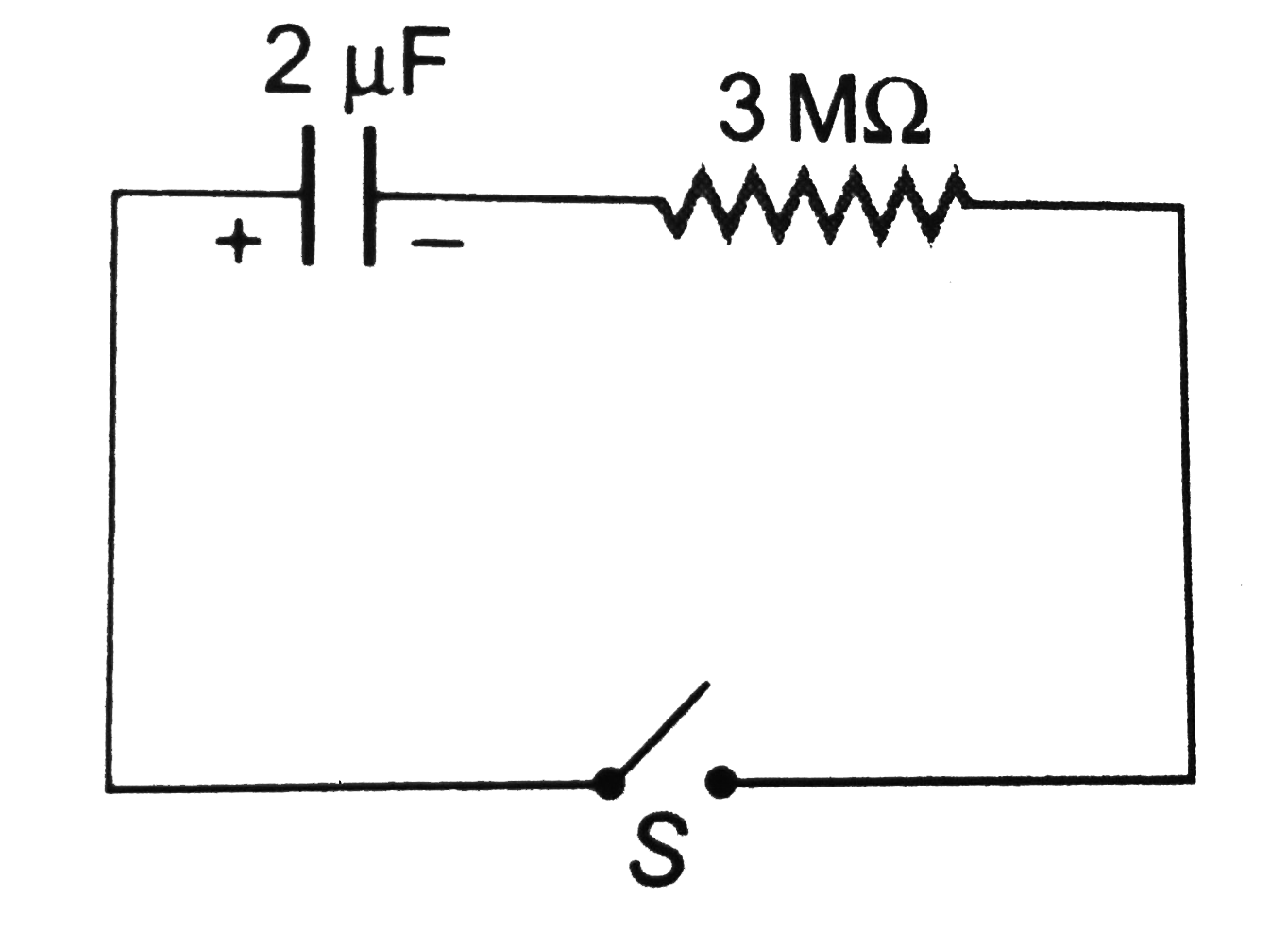 View Solution
In the circuit shown in figure. Charge stored in 6μF capacitor will be (C=6μF)
 View Solution

