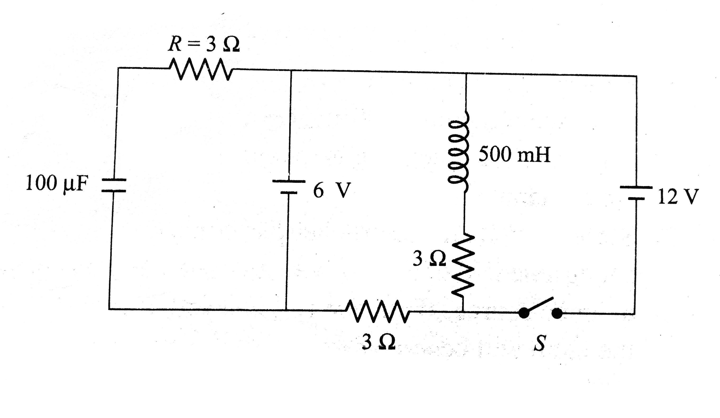
In the given circuit Fig the switch is closed at t=0. Choose the correct answers.

Current in the inductor when the circuit reaches the steady state is 4A.
The net change in flux in the inductor is 1.5Wb.
The time constant of the circuit after closing S is 555.55s
The charge stored in the capacitor in steady state is 1.2mC.
The correct Answer is:A, B
At t<0,IL=66=1A
At t>>0,IL=123=4A
∴|ϕ|=L[if−ii]=500×10−3×3=1.5Wb<br>:. (a) and (b) are the corrent choices.
Topper's Solved these Questions
- BOOK - CENGAGE PHYSICSCHAPTER - INDUCTANCEEXERCISE - Exercises (assertion-reasoning)2videos
INDUCTANCE
- BOOK - CENGAGE PHYSICSCHAPTER - INDUCTANCEEXERCISE - Exercises (linked Compreshension)36videos
INDUCTANCE
- BOOK - CENGAGE PHYSICSCHAPTER - INDUCTANCEEXERCISE - Exercises (single Correct )65videos
INDUCTANCE
- BOOK - CENGAGE PHYSICSCHAPTER - HEATING EFFECT OF CURRENTEXERCISE - Thermal Power in Resistance Connected in Circuit28videos
HEATING EFFECT OF CURRENT
- BOOK - CENGAGE PHYSICSCHAPTER - KINETIC THEORYEXERCISE - Question Bank31videos
KINETIC THEORY
Similar Questions
Knowledge Check
- Question 1 - Select One or More
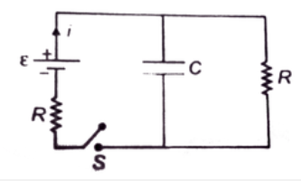
In the circuit shows in Fig the switch is closed at t=0.
 AAt t=0,I1=I2=0BAt any time t,I0I2=L2L1CAt any time t, I1+I2=εRDAt t=∞,I1 and I2 are independent of L1 and L2
 - Question 2 - Select One or More

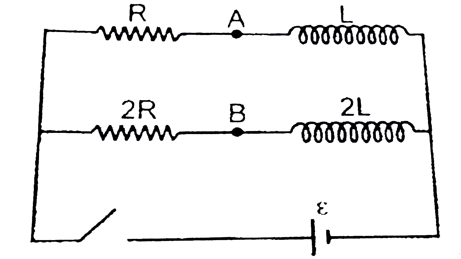
In given LR circuit the switch S is closed at time t=0 thenAThe ratio of induced emfs in the inductors of inductance L and 2L will be constantBThe ratio of induced emfs in the inductor of inductance L and 2L will be time varyingCthe potential difference VA−VB increases with timeDThe potential difference VA−VB will be constant
In the given circuit, the switch S is closed at time t=0 then select the correct statement for current l in resistance PQ as shown in the figure
_PHY_E05_091_Q01.png) View Solution
View SolutionIn the given circuit, the switch S is closed at time t = 0, then select the correct statement for current l in resistance PQ as shown in the figure.
_PHY_E05_045_Q01.png) View Solution
View SolutionIn the circuit shown, the switch is closed at t=0. Select the correct alternative(s)
 View Solution
In the following circuit (Fig.) the switch is closed at t=0. Find the current i1,i2,i3 and di3/dt at t=0 and at t=∞. Initially, all current are zero.
 View Solution
In the following circuit (Fig.) the switch is closed at t=0. Find the current i1,i2,i3 and di3/dt at t=0 and at t=∞. Intitially, all current are zero.
 View Solution
In the following circuit (Fig.) the switch is closed at t=0. Find the current i1,i2,i3 and di3/dt at t=0 and at t=∞. Intitially, all current are zero.
 View Solution

