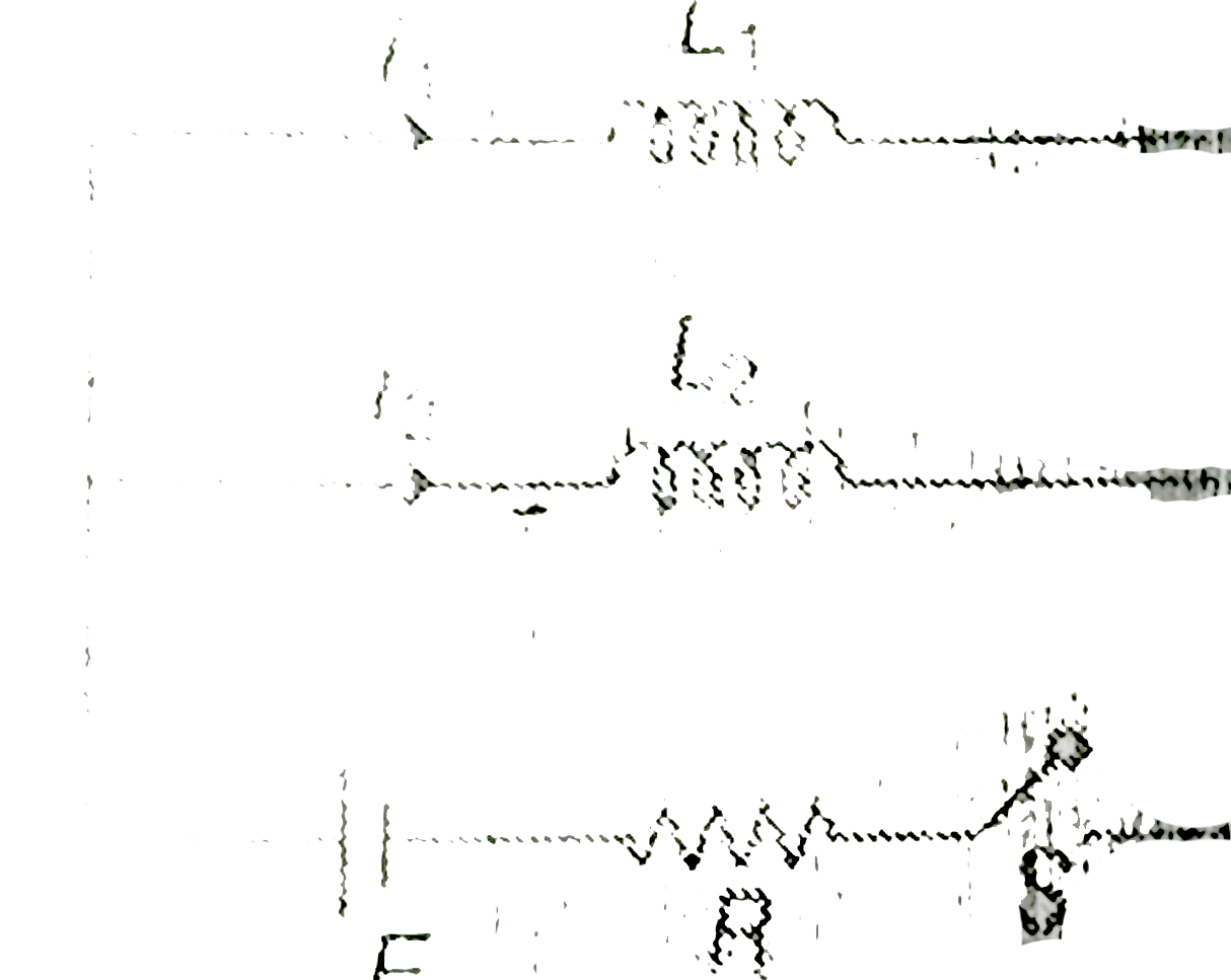
In the shown AC circuit phase different between current I1 and I2 is
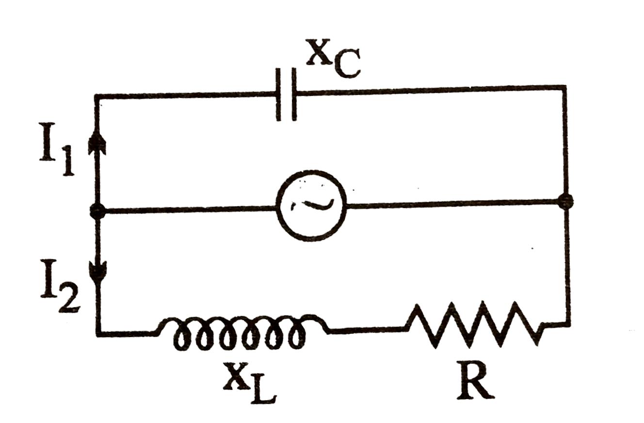
a.π2−tan−1.xLR
b.tan−1−XL−XCR
c.π2+tan−1.xLR
d.tan−1.XL−XCR+π2
The correct Answer is:C
Step by step video & image solution for In the shown AC circuit phase different between current I_(1) and I_(2) is by Physics experts to help you in doubts & scoring excellent marks in Class 12 exams.
Similar Questions
In the circuit shown in figure :
R=10Ω,L=√310H,R2=20Ω and C=√32mF. Current in L−R1 circuit is I1 in C−R1 circuit is I2 and the main current is I
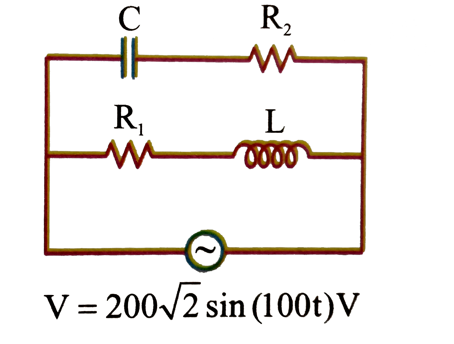
Phase difference between I1 and I2 isView SolutionIn the circuit shown in figure :
R=10Ω,L=√310H,R2=20Ω and C=√32mF. Current in L−R1 circuit is I1 in C−R1 circuit is I2 and the main current is I

Phase difference between I1 and I2 isView SolutionA seriesLCR circuit is connected to an ac voltage source. When L is removed from the circuit, the phase difference between current and voltage is π3. If instead C is removed from the circuit phase difference is again π3 between current and voltage. Power factor of circuit is:
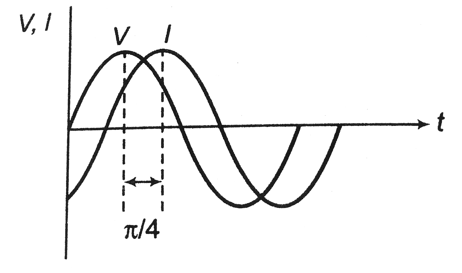
View SolutionAn Ac voltage V=V0sin100t is applied to the circuit, the phase difference between current and voltage is found to be π4, then
 .View Solution
An Ac voltage V=V0sin100t is applied to the circuit, the phase difference between current and voltage is found to be π4, then
 .View Solution
An 8 H inductor, a 2 μF capacitor and a 100 Ω resistor are connected in series to an A.C. supply of 220 V and 50 Hz. Calculate :
(i) Impedance of the circuit.
(ii) Current flowing through the circuit.
(iii)Phase difference between the current and the supply voltage.
(iv) Average power consumed by the circuit.View SolutionThere is a 5Ω resistance in an AC, circuit. Inductance of 0.1H is connected with it in series. If equation of AC emf is 5sin50t then the phase difference between current and e.m.f. is
View SolutionFor wattless power is an AC circuit, the phase angle between the current and voltagge is
View Solution(i) In the circuit shown in Figure below, calculate phase difference between the current and the supply voltage:
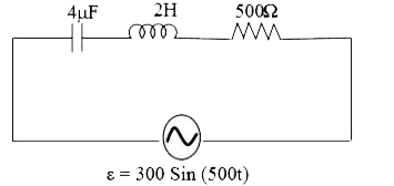
(ii) State whether current is leading or lagging behind the supply voltageView SolutionIn the circuit shown in the figure The steady state currents i1andi2 in the coils after the switch S is closed are
 View Solution

