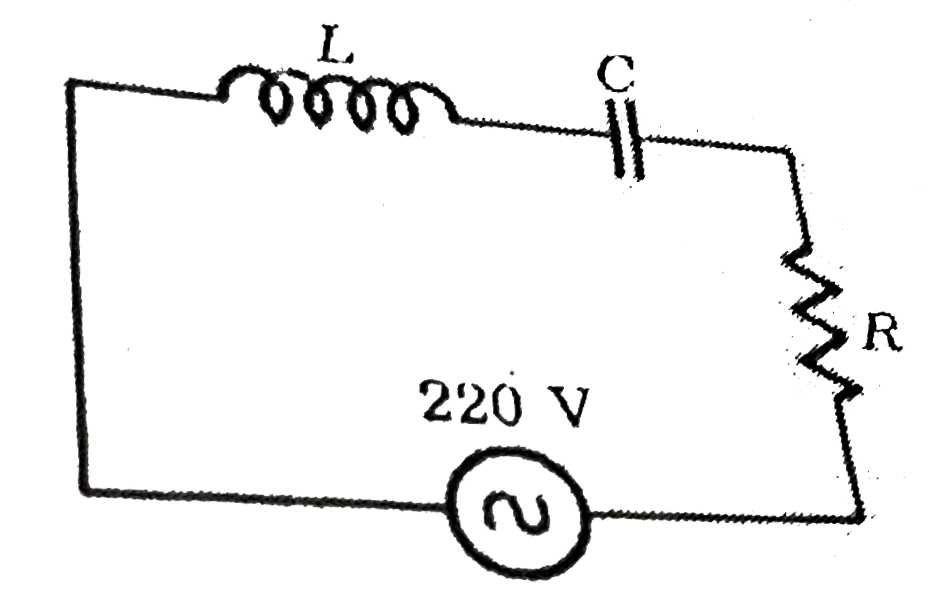
Obtain the answers to (a) and (b) Q.13, if the circuit is connected to a high frequency supply (240 V , 10 kHz). Hence explain statement that at very high frequency. Inductor in circuit nearly amount to open circuit. How does an indcutor behave in a d.c. circuit after the steady state ?
Here, v=10kHz=104Hz.Ω=2πv=2π×104rad/s.
I0=E0√R2+ω2L2=√2×240√104+4π2×0.52=1.08×10⁻² amp.
Here, contribution of term containing R is negligible
tanϕ=ωLR=2π×104×0.5100=100π, which is very large ∴ϕ→ tends to 90∘ or π2 radian
On comparision, we find that at low frequencies, I0=1.82 amp.
at high frequencies, I0=0.0108 amp.
∴ At high frequencies, L offers very high resistance which amounts to an open circuit (infinite resistance). In a d.c. circuit, after steady state ω=0. Therefore, XL=ωL=0. Hence L acts like a pure conductor of negligible inductive reactance. It has no role to play.
Topper's Solved these Questions
- BOOK - PRADEEPCHAPTER - ELECTROMAGNETIC INDUCTION & ALTERNATING CURRENTEXERCISE - Solved Examples (b)1videos
ELECTROMAGNETIC INDUCTION & ALTERNATING CURRENT
- BOOK - PRADEEPCHAPTER - ELECTROMAGNETIC INDUCTION & ALTERNATING CURRENTEXERCISE - Short Answer Qusetions2videos
ELECTROMAGNETIC INDUCTION & ALTERNATING CURRENT
- BOOK - PRADEEPCHAPTER - DUAL NATURE OF RADIATION AND MATTEREXERCISE - Exercise191videos
DUAL NATURE OF RADIATION AND MATTER
- BOOK - PRADEEPCHAPTER - ELECTROMAGNETIC WAVESEXERCISE - II Focus multiple choice question5videos
ELECTROMAGNETIC WAVES
Similar Questions
Obtain the answers (a) to (b) in Exercise 7.13 if the circuit is connected to a high frequency supply (240 V, 10 kHz). Hence, explain the statement that at very high frequency, an inductor in a circuit nearly amounts to an open circuit. How does an inductor behave in a d.c. circuit after the steady state ?
View SolutionObtain the answers to (a) and (b) above in Exercise 7.15 if the circuit is connected to a 110 V, 12 kHz supply ? Hence, explain the statement that a capacitor is a conductor at very high frequencies. Compare this behaviour with that of a capacitor in a d.c. circuit after the steady state
View Solution
Knowledge Check
- Question 1 - Select One
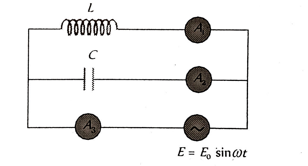
An inductor L and a capacitor C are connected in the circuit as shown in the figure. The frequency of the power supply is equal to the resonant frequency of the circuit. Which ammeter will read zero ampere
 AA1BA2CA3DNone of these
Obtain the answers to (a) and (b) in Q .15, if the circuit is connected to 110 V, 12 kHz supply. Hence explain the statement that a capacitor is a conductor at very high frequencies. Compare this behaviour with that of a capacitor in d.c. after the steady state.
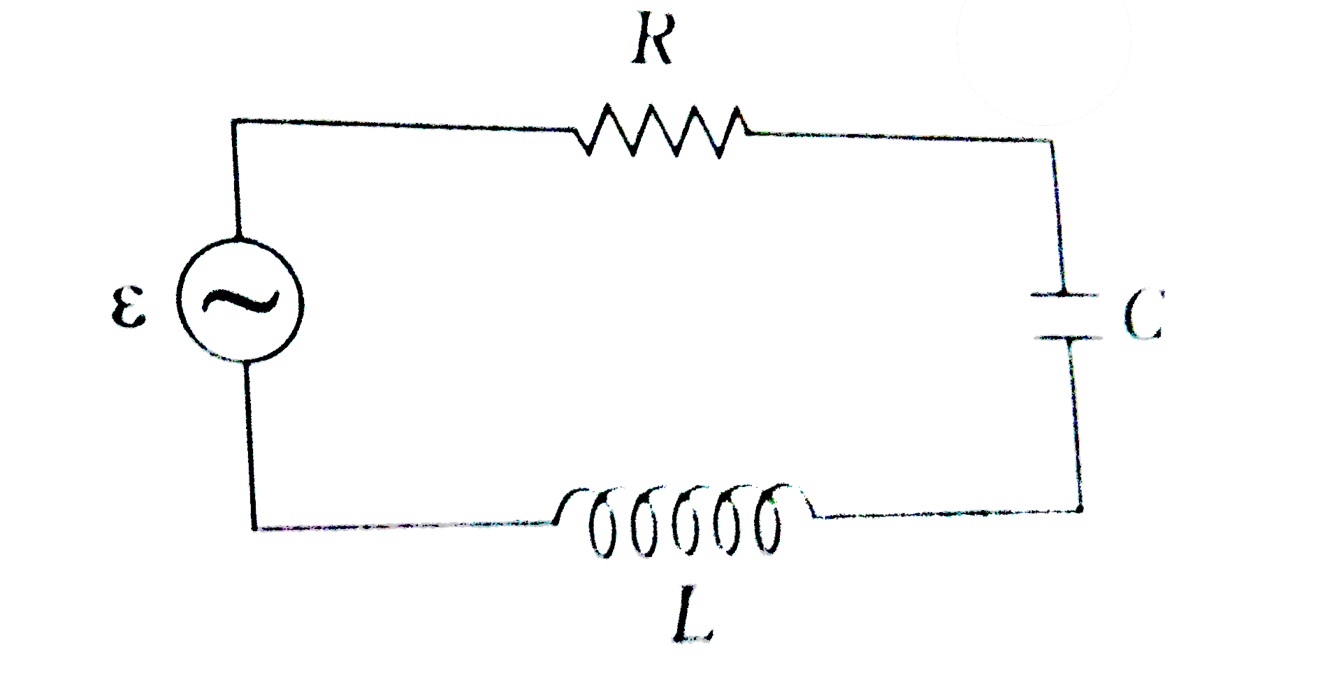
View SolutionFigure here, shows a series L-C-R circuit connected to a variable frequency 230 V source. L = 5.0H, C = 80μF and r =40Ω
(a) Determine the source frequency which drives the circuit in resonance.
(b) Obtain the impedance of the circuit and the amplitude of current at the resonating frequency.
(c) Determine the rms potential drops across the three elements of the circuit. show that the potential drop across the L-C combination is zero at the resonating frequency.
 View Solution
A series L-C-R circuit with R = 20Ω, L = 1.5 H and C =35μF is connected to a variable frequency 200 V, AC supply. When the frequency of the supply equals the natural frequency of the circuit, what is the average power transfered to the circuit, what is the average power transfered to the circuit in one complete cycle ?
View SolutionA series LCR circuit with r=10ohm,L=2H and C=25μF is connected to a varialbe frequency 200 V a.c. supply. When the frequency of the supply equals the natural frequency of the circuit, what is the average power transferred to the circuit in one complete cycle ?
View SolutionFig 14.18 shows a series LCR circuit connected to a variable frequency 200 V source:
L=4.0H,C=100μF and R=40Ω.
(i) Calculate the resonant frequency of the circuit.
(ii) Obtain the impedance of the circuit and the amplitude of the current at resonating frequency.
(iii) Determine r.m.s. potential drop across L.
 View Solution
A series LCR circuit with R=20Ω , L = 1.5 H and C = 35 μF is connected to a variable-frequency 200 V a.c. supply. When the frequency of the supply equals the natural frequency of the circuit, what is the average power transferred to the circuit in one complete cycle ?
View SolutionA series LCR circuit with R=20Ω,L=1.5H and C=35μF is connected to a variable frequency 200V ac supply. When the frequency of the supply equals the natural frequency of the circuit, what is the average power in Kw transferred to the circuit in one complete cycle?
View Solution

