Shows a wire of length l which can slide on a U- shaped rail of negligible resistance. The resistance of the wire is R. The wire is pulled to the right with a constant speed v. Draw an equivalent circuit diagram representing the induced emf by a battery. Find the current in the wire using this diagram.
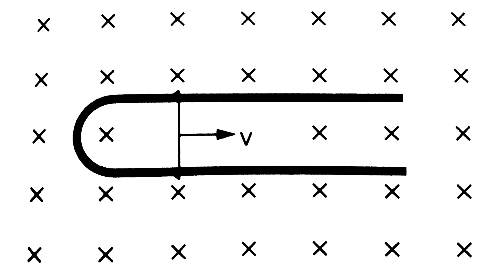
The emf is induced due to the moving wire
The magnitude of theis emf is ε=vBl
As the wire moves towards right, the force vec qv X vecB on a positive charge acts in the upward direction in the figure
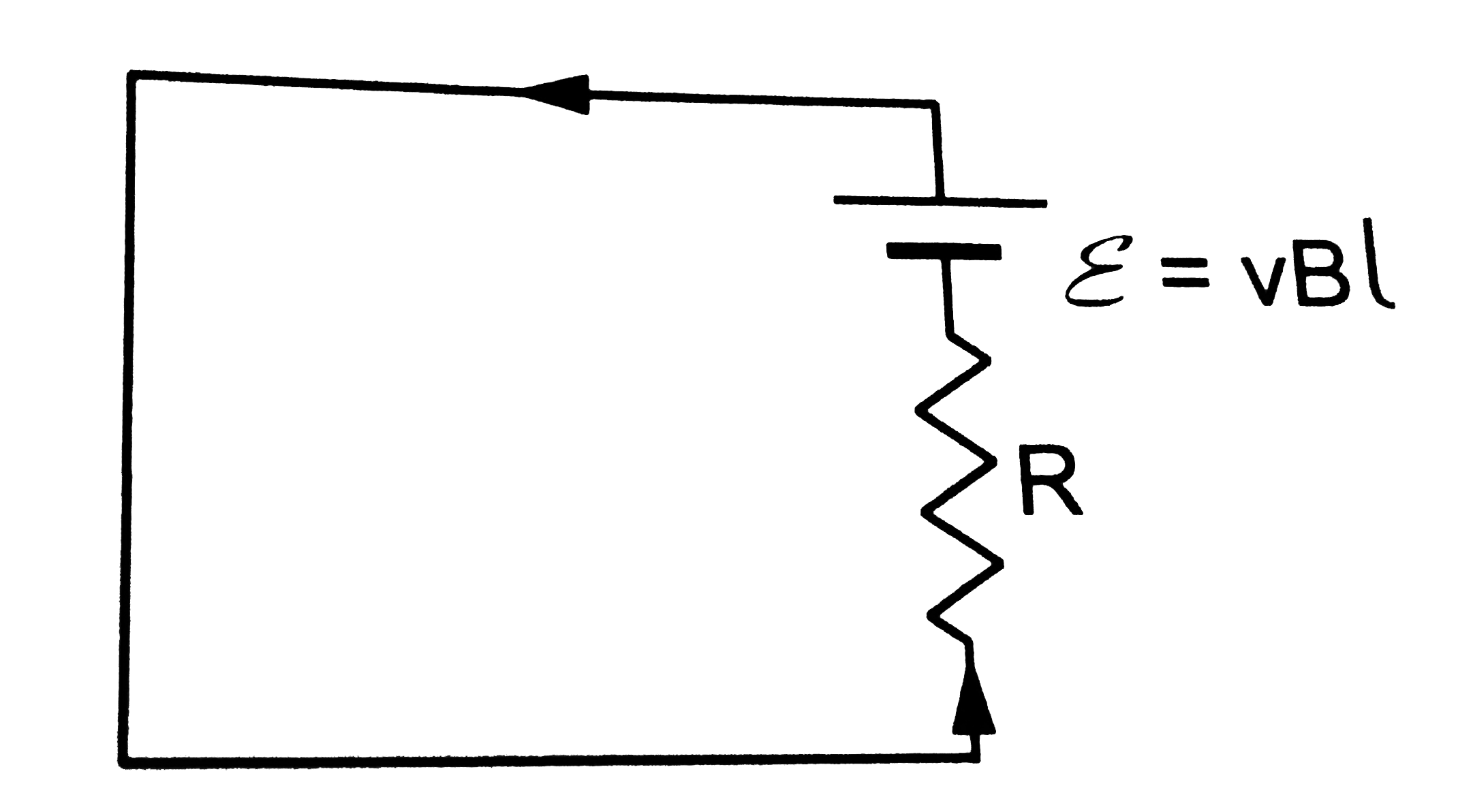
The positve terminal of the equivalent battery appears upwards
The resistance of the wire acts as the internal resistance of the equivalent battery
The equivalent circuit is drawn i fingure(38
W8b
) The current in the circuit is , from Ohm's law, i=εR=vBlR
It is in the upward direction along the wire
Topper's Solved these Questions
- BOOK - HC VERMACHAPTER - ELECTROMAGNETIC INDUCTIONEXERCISE - Short Answer13videos
ELECTROMAGNETIC INDUCTION
- BOOK - HC VERMACHAPTER - ELECTROMAGNETIC INDUCTIONEXERCISE - Objective 112videos
ELECTROMAGNETIC INDUCTION
- BOOK - HC VERMACHAPTER - ELECTROMAGNETIC INDUCTIONEXERCISE - EXERCISE9videos
ELECTROMAGNETIC INDUCTION
- BOOK - HC VERMACHAPTER - ELECTRIC FIELD AND POTENTIALEXERCISE - Exercises75videos
ELECTRIC FIELD AND POTENTIAL
- BOOK - HC VERMACHAPTER - ELECTROMAGNETIC WAVESEXERCISE - Exercises9videos
ELECTROMAGNETIC WAVES
Similar Questions
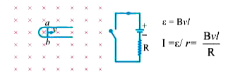
Figure shows a wire ab of length l which can slide on a U-shaped rail of negligible resistance. The resistance of the wire is R. The wire is pulled to the right with a constant speed v. Draw an equivalent circuit diagram representing the induced emf by a battery. Find the current in the wire.
 View Solution
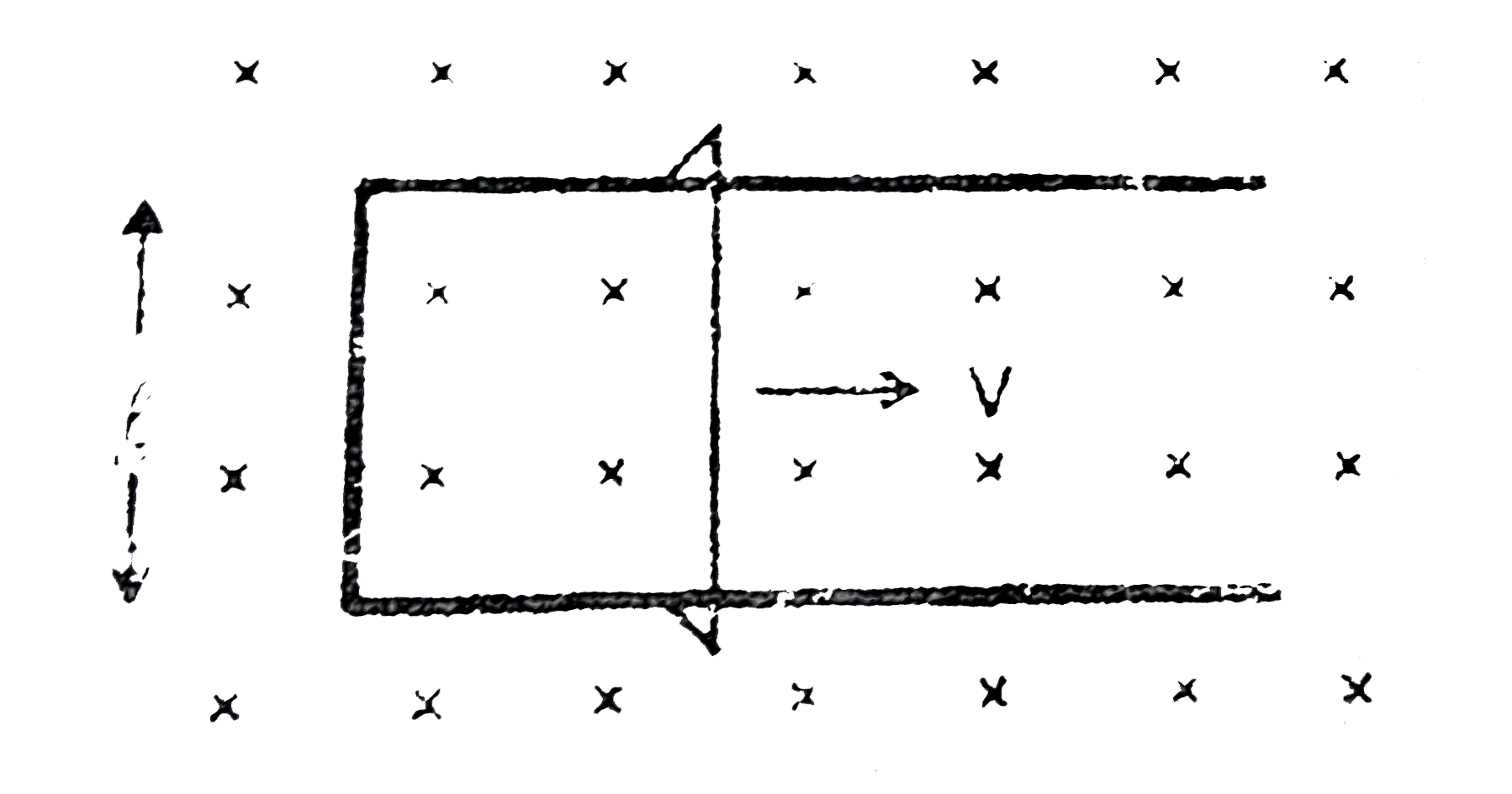
A long U-shaped wire of width l placed in a perpendicular uniform and constant magnetic field B (figure).A wire of length l is slid on the U-shaped wire with a constant velocity v towards right.The resistance of all the wires is r per unit length.At t=0, the sliding wire is close to the left edge of the fixed U-shaped wire.Draw an equivalent circuit diagram at time t, showing the induced emf as a battery.Calculate the current in the circuit.
 View Solution
Knowledge Check
- Question 1 - Select One
A wire of length 100 cm is connected to a cell of emf 2 V and negligible internal resistance. The resistance of the wire is 3Ω. The additional resistance required to produce a potential drop of 1 milli volt per cm is
A60ΩB47ΩC57ΩD35Ω - Question 2 - Select One
Imagine a would where free magnetic charges exist. In this world, a circuit is made with a U shape wire and a rod free to slide on it. A current carried by free magnetic charges can flow in the circuit. When the circuit is placed in a uniform electric field. E perpendicular to the plane of the plane of the circuit and the rod is pulled to the right with a constant speed v, the "magnetic EMF" in the current and the direction of the corresponding current. arising because of changing electric flux will be (l is the length of the rod and c is speed of light).
AvEl clockwiseBvEL counterclockwiseCvElc2 clockwiseDvElc2 counterclockwise
Imagine a would where free magnetic charges exist. In this world, a circuit is made with a U shape wire and a rod free to slide on it. A current carried by free magnetic charges can flow in the circuit. When the circuit is placed in a uniform electric field. E perpendicular to the plane of the plane of the circuit and the rod is pulled to the right with a constant speed v, the "magnetic EMF" in the current and the direction of the corresponding current. arising because of changing electric flux will be (l is the length of the rod and c is speed of light).
View SolutionFigure shows a wire ab of length L and resistance R which can slide on a smooth pair of rails. Ig is current generator which supplies a constant current i in the circuit. If the wire ab slide at a speed v towards right, find the potential difference below a and b

(b) The current generator Ig show in the figure sends a constant current i through the circiut. The wire ab has a length L and mass m and can slide on the smooth horizontal rails connect to Ig . The entire system lies in a vertical magnetic field B . Find the velocity of the wire as a function of time.

(c) The system containing the rails and the wire of the previous part is kept vertically in a uniform horizontal magnetic field B that is perpendicular to the plane of the rails (figure). If is found that the wire stays in equilibrium. If th ewire ab is replaced by another wire of double its mass, how long will lit take in falling through a distance equal to its length?
The current generator Ig shown in figure sends a constant current i through the circuit. The wire cd is fixed and wire ab is made to slide on the smooth, thick rails with a constant velocity v toward right. Each of these wires has resistance r . Find the current through the wire cd .
 View Solution
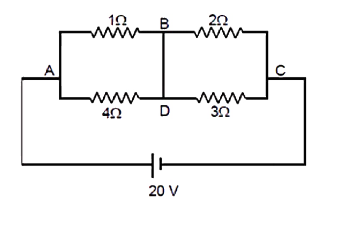
In the given circuit diagram , a connecting wire of negligible resistance is joining the points B and D, the current in the connecting wire is
 View Solution
In the diagram shown, all the wires have resistance R. The equivalent resistance between the upper and lower dots shown in the diagram is :
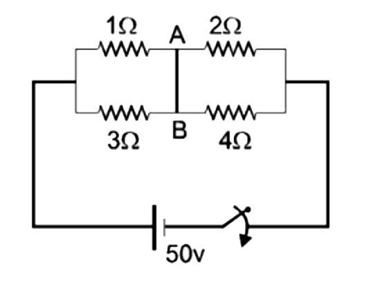
View SolutionFor resistances are connected by an ideal battery of emf 15 V, the circuit is in steady - state then the current (in ampere) in wire AB is :
 View Solution
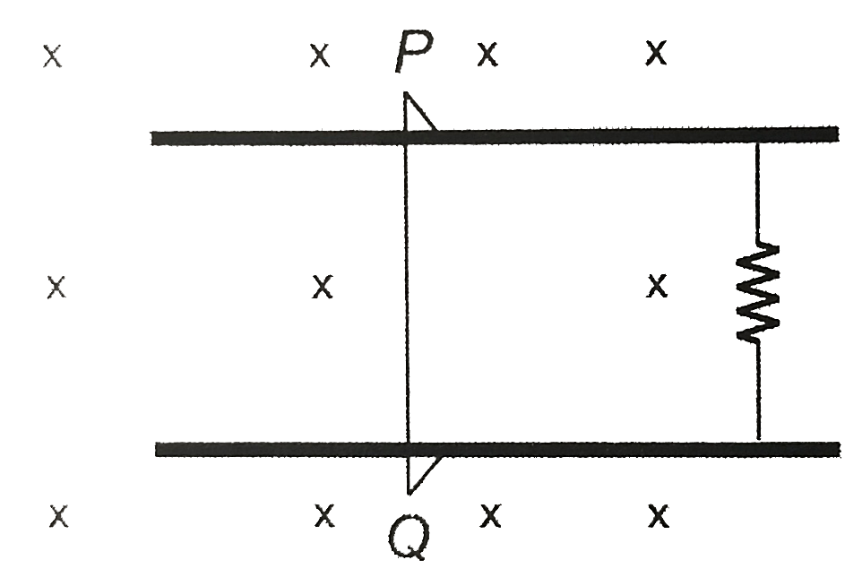
Consider the situation shown in the figure. The wire PQ has mass m , resistance r and can slide 0n the smooth, horizontal parallel rails separated by a distance l . The resistance of the rais is negiligible. A uniform magnetic field B exists in the reactangular region and a resistance R connects the rail outside the field region. At t=0 , the wire PQ is pushed toward right with a speed v0 . Find
(a) the current in the loop at an instant when the speed of the wire PQ is v
(b) the acceleration of the wire as this instant
(c) the velocity v as a function of x
(d) the maximum distance the wire will move
(e) the velocity as a function of time
 View Solution

