State ohm's law.
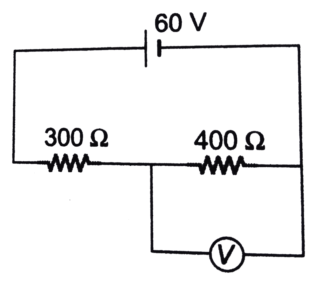
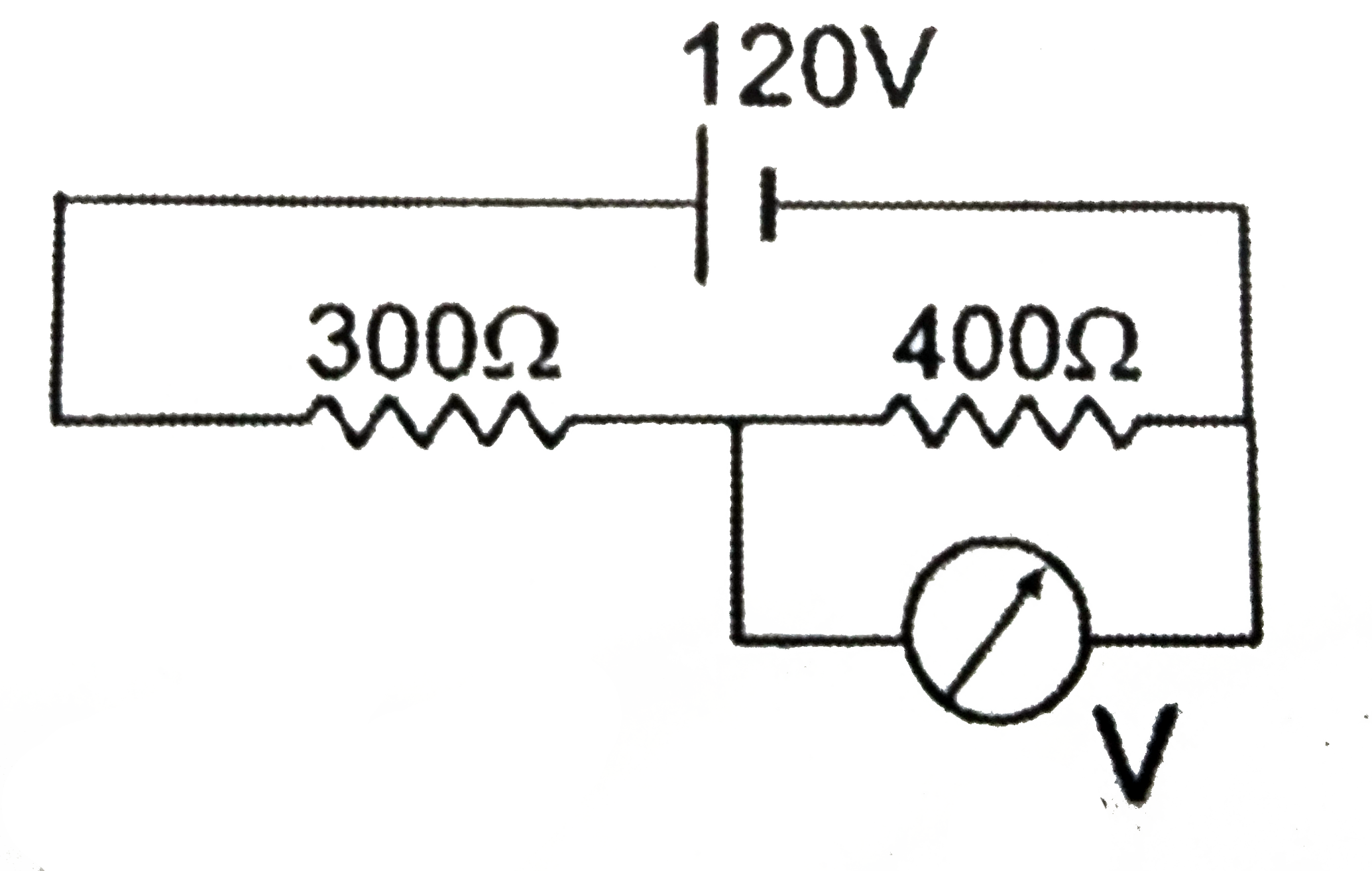
In the circuit shown in figure, a voltmeter reads 30 volts when it is connected across 400 ohm resistance. Calculate what the same voltmeter will read when it is connected across the 300 ohm resistance.
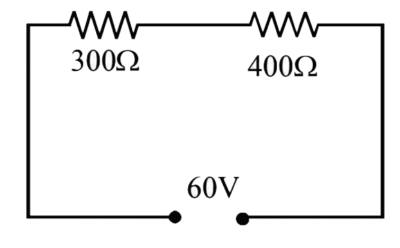
30V
12.5V
15V
22.5V
The correct Answer is:D
Change in the resistance of the conductor on increasing its temperature
R−R0=R0αav(T−T0)
The disks will be effectively in series, so we will add the resistance to get the total. Looking only at pair of disk, we have
Rc+Ri=R0C(T−T0)+R0i(αi(T−T0)+1)
=R0C+R0i+(R0Cαc+R0iαi)(T−T0)
This equation will only be constant if the coefficient for the term (T−T0) vanishes.
ThenR0c+αc+R0iαi=0
but R=pL/A, and the disks have the same cross sectional area, so
Lcρcαc+Liρiαi=0
orLcLi=−ρiαiρcαc=−9.68×10−8×6.5×10−33500×10−8×(−0.50×10⁻³)=0.036
Topper's Solved these Questions
- BOOK - NCERT FINGERTPS ENGLISHCHAPTER - CURRENT ELECTRICITYEXERCISE - EXEMPLAR PROBLEMS6videos
CURRENT ELECTRICITY
- BOOK - NCERT FINGERTPS ENGLISHCHAPTER - CURRENT ELECTRICITYEXERCISE - CORNER15videos
CURRENT ELECTRICITY
- BOOK - NCERT FINGERTPS ENGLISHCHAPTER - CURRENT ELECTRICITYEXERCISE - POTENTIOMETER7videos
CURRENT ELECTRICITY
- BOOK - NCERT FINGERTPS ENGLISHCHAPTER - COMMUNITCATION SYSTEMSEXERCISE - Assertion And Reason30videos
COMMUNITCATION SYSTEMS
- BOOK - NCERT FINGERTPS ENGLISHCHAPTER - DUAL NATURE OF RADIATION AND MATTER EXERCISE - Assertion And Reason15videos
DUAL NATURE OF RADIATION AND MATTER
Similar Questions
Knowledge Check
- Question 1 - Select One
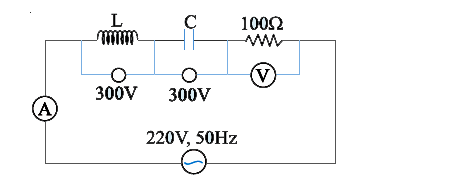
In the circuit shown in figure, what will be the reading of the voltmeter ?
 A300 VB900 VC200 VD400 V
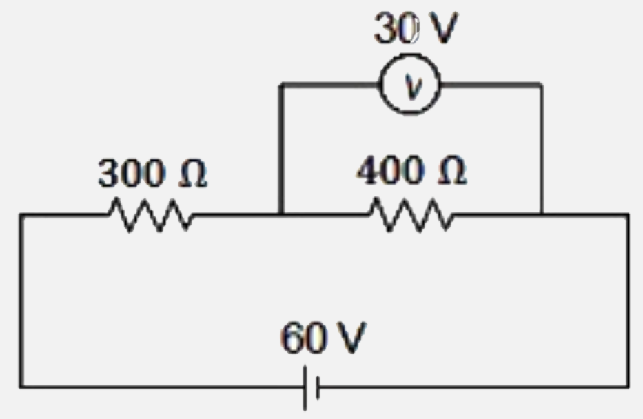
In the circuit figure, the voltmeter reads 30 V. The resistance of the voltmeter is
 View Solution
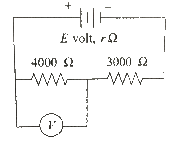
In Fig.6.59, when an ideal voltmetre is connected across 4000Ω resistance, it reads 30V. If the voltmeter is connected across 3000Ω resistance, it will read
 View Solution
In the circuit shown, reading of the voltmeter connected across 400Ω resistance is 60 V. If it is connected across 300Ω resistance then reading in volt will be
 View Solution
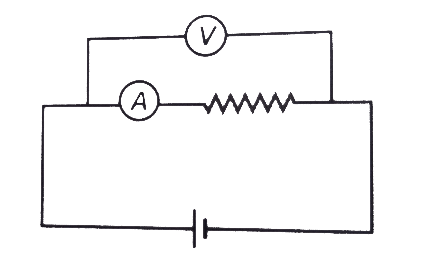
Assertion : In the circuit shown in figure ammeter and voltmeter are non-ideal when positions of ammeter and voltmeter are changed, reading of ammeter will increase while of voltmeter will decrease.
Reason : Resistance of an ideal ammeter is zero while that of an ideal voltmeter is infinite.View SolutionThe voltmeter shown in the figure reads 10V across 40 ω . The resistance of voltmeter is
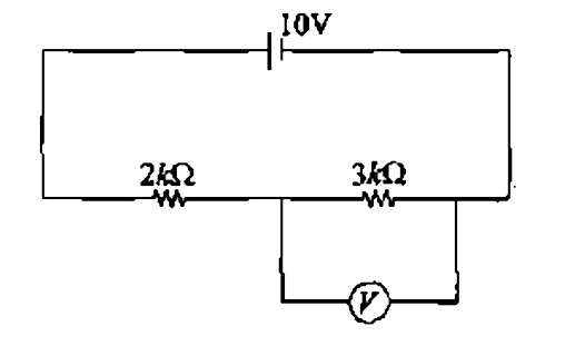
View SolutionIn the circuit shown in figure-3.334, the resistance of voltmeter is6kΩ. The voltmeter reading will be :
 View Solution
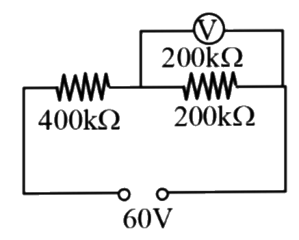
A constant 60 V supply is connected across the two resistors as shown in diagram. Calculate the reading of the voltmeter which has a resistance of 200 KΩ
 View Solution


