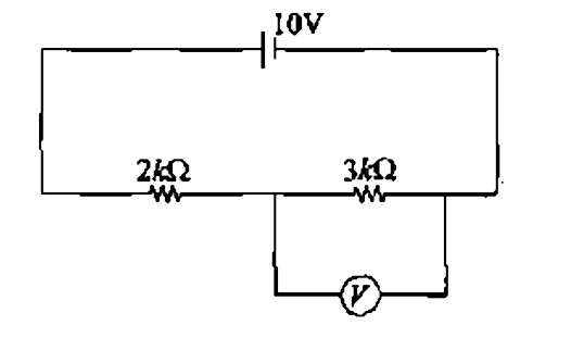
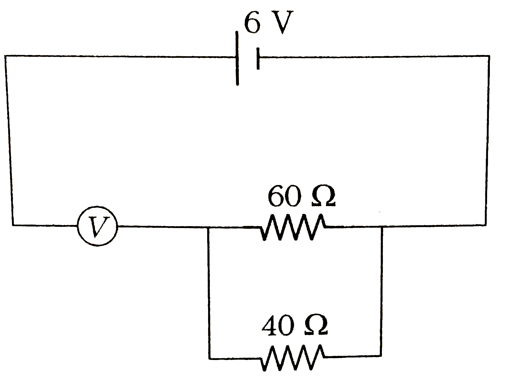
In the circuit shown in figure-3.334, the resistance of voltmeter is. The voltmeter reading will be :
The correct Answer is:B
Net resistance of and voltmeter is also . Now, the applied is equally distributed between Hence, reading of voltmeter
Topper's Solved these Questions
- CURRENT ELECTRICITYBook:DC PANDEY ENGLISHChapter:CURRENT ELECTRICITYExercise:Level 2 More Than One Correct
Explore 10 Videos
- CURRENT ELECTRICITYBook:DC PANDEY ENGLISHChapter:CURRENT ELECTRICITYExercise:Level 2 Comprehension Example Type
Explore 2 Videos
- CURRENT ELECTRICITYBook:DC PANDEY ENGLISHChapter:CURRENT ELECTRICITYExercise:Level 1 Subjective
Explore 53 Videos
- COMMUNICATION SYSTEMBook:DC PANDEY ENGLISHChapter:COMMUNICATION SYSTEMExercise:Subjective
Explore 11 Videos
- ELECTROMAGNETIC INDUCTIONBook:DC PANDEY ENGLISHChapter:ELECTROMAGNETIC INDUCTIONExercise:Medical entrances gallery
Explore 25 Videos
Similar Questions
Knowledge Check
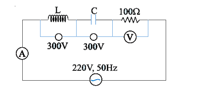
In the circuit shown in figure, what will be the reading of the voltmeter ?
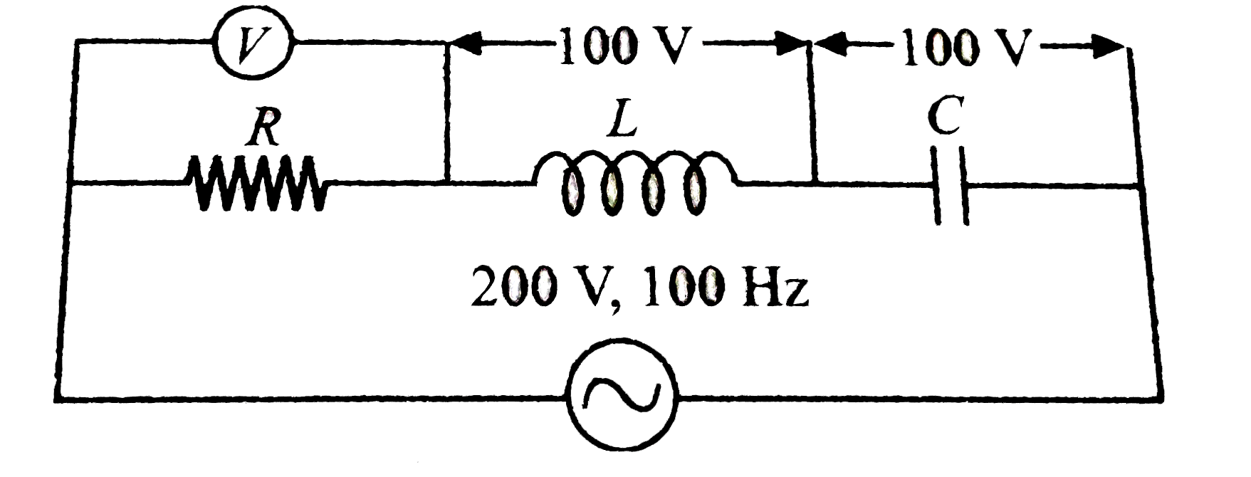 A300 VB900 VC200 VD400 V
In the circuit shown in figure neglecting source resistance the voltmeter and ammeter reading will respectively, will be
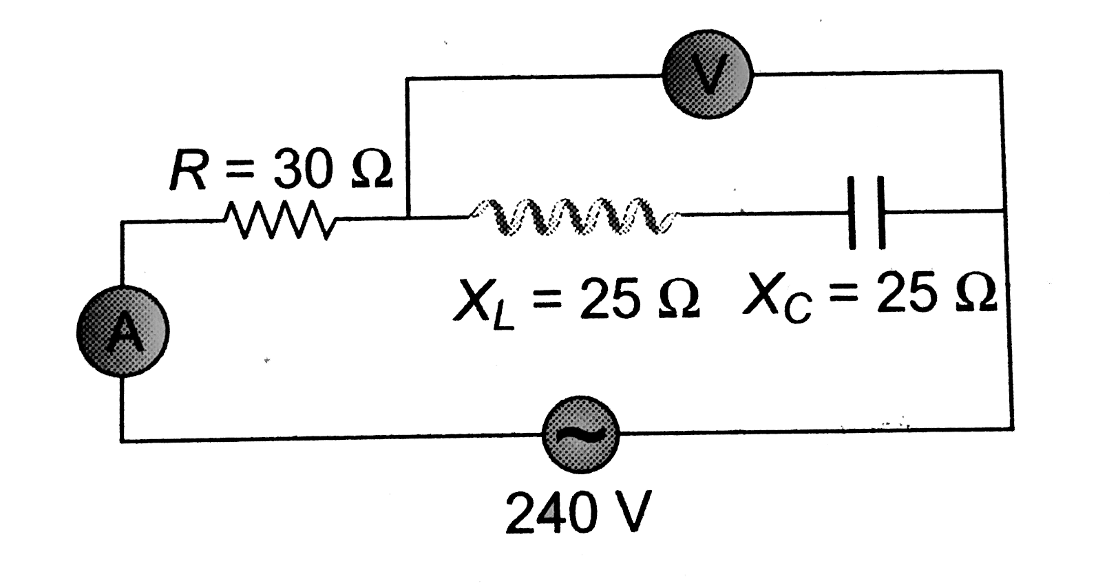
View SolutionIn the circuit shown in figure neglecting source resistance, the voltmeter and ammeter reading will respectively be

View SolutionIn the circuit shown in the figure, the voltmeter reading is
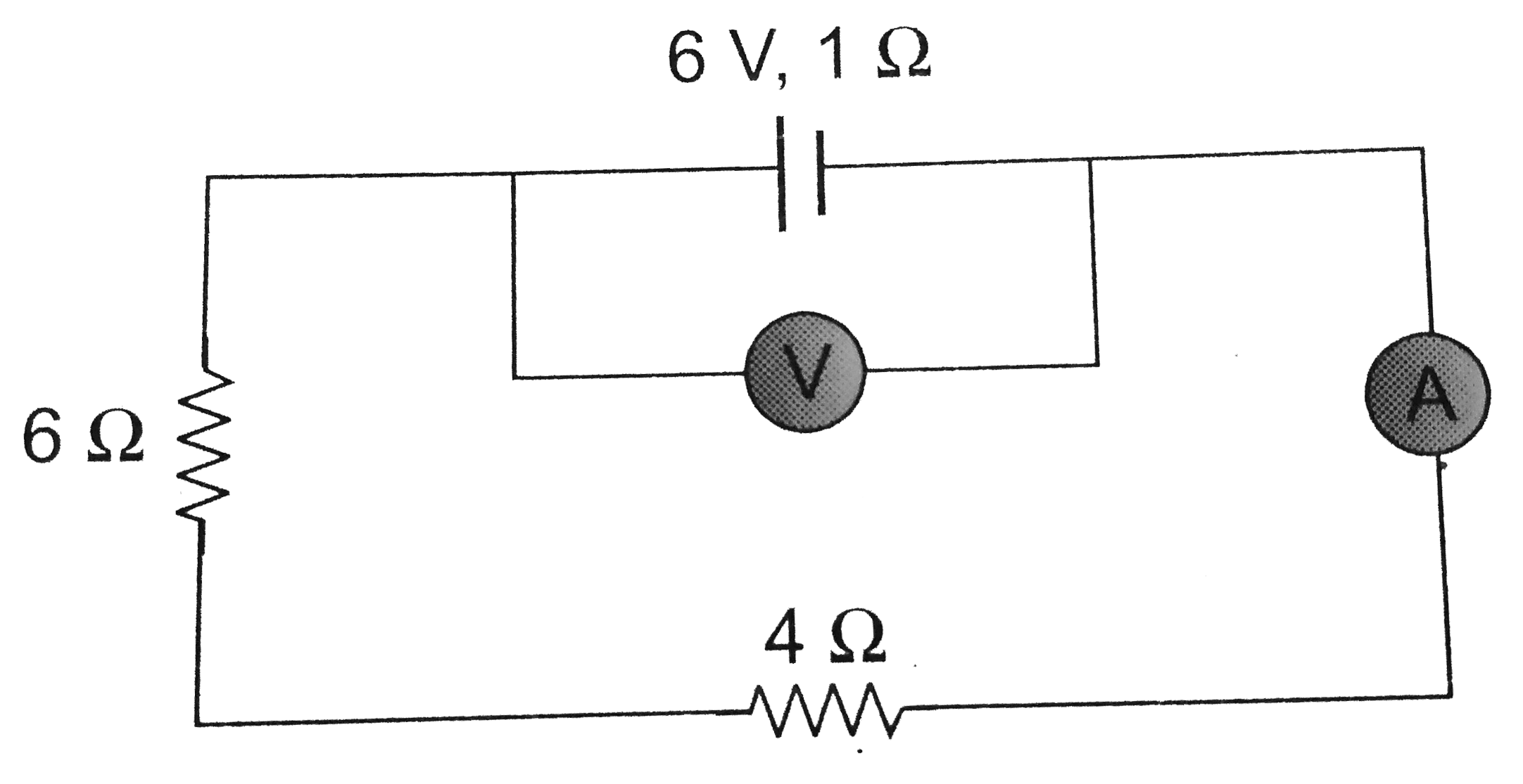
View SolutionIn the circuit shown here, the readings of the ammeter and voltmeter are
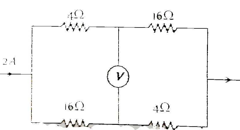
View SolutionAn ideal voltmeter V and ideal ammeter A are connected in a circuit as shown in the figure. If the reading of the voltmeter is 32 V, the reading of ammeter will be
View SolutionIn the circuit shown below. The reading of the voltmeter V is
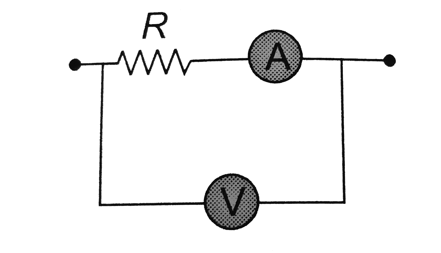
View SolutionIn the circuit shown the resistance of voltmeter is 10000ohm and that of ammeter is 20ohm. The ammeter reading is 0.10amp and voltmeter reading is 12 volts. Then R is equal to
View Solution
