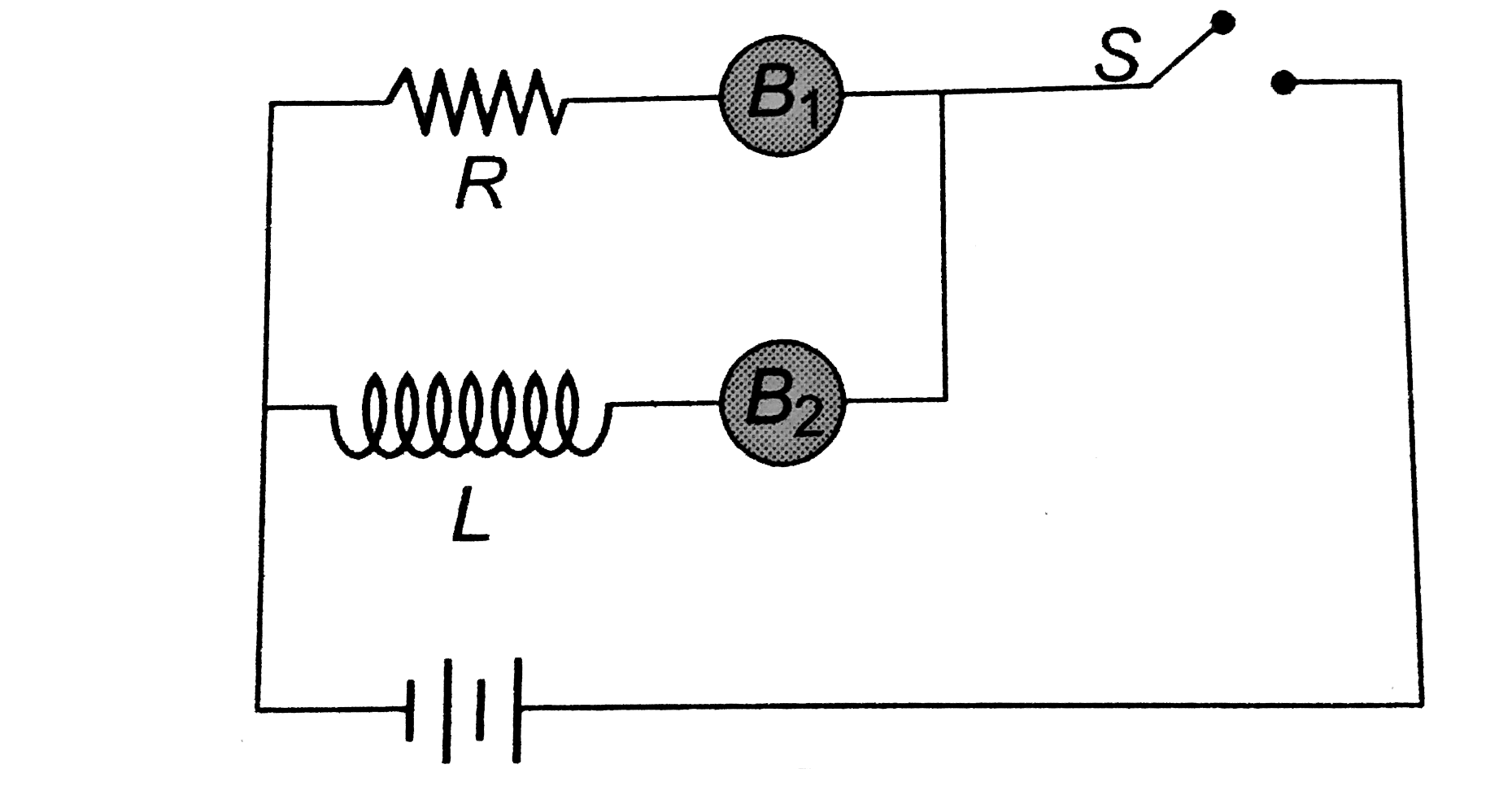
The adjoining figure shows two bulbs B1andB2 resistor R and an inductor L. When the switch S is turned off
Both B1andB2 die out promptly
Both B1andB2 die out with some delay
B1 dies out promptly but B1 with some delay
B2 dies out promptly but B1 with some delay
Current in B1 will promptly become zero while current in B2 will slowly tend to zero.
Topper's Solved these Questions
- E.M. INDUCTION AND A.C. CURRENTS BOOK - MODERN PUBLICATIONCHAPTER - E.M. INDUCTION AND A.C. CURRENTS EXERCISE - MULTIPLE CHOICE QUESTIONS LEVEL-II
51 Videos
- E.M. INDUCTION AND A.C. CURRENTS BOOK - MODERN PUBLICATIONCHAPTER - E.M. INDUCTION AND A.C. CURRENTS EXERCISE - MULTIPLE CHOICE QUESTIONS LEVEL -III (QUESTIONS FROM AIEEE/JEE EXAMINATION)
14 Videos
- DESCRIPTION OF MOTION IN TWO AND THREE DIMENSIONBOOK - MODERN PUBLICATIONCHAPTER - DESCRIPTION OF MOTION IN TWO AND THREE DIMENSIONEXERCISE - Revision TEST
36 Videos
- ELECTROMAGNETIC WAVESBOOK - MODERN PUBLICATIONCHAPTER - ELECTROMAGNETIC WAVESEXERCISE - RECENT COMPETITIVE QUESTIONS
4 Videos
Similar Questions
Knowledge Check
Figure represents two bulbs B1 and B2, resistor R and an inductor L. When the switch S is turned off
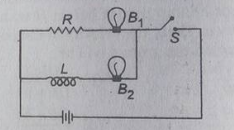 Aboth B1 and B2 die out promptlyBboth B1 and B2 die out with some delayCB1 dies out promptly but B2 with some delayDB2 dies out promptly but B1 with some delay
Figure represents two bulbs B1 and B2, resistor R and an inductor L. When the switch S is turned off
 Aboth B1 and B2 die out promptlyBboth B1 and B2 die out with some delayCB1 dies out promptly but B2 with some delayDB2 dies out promptly but B1 with some delay
Figure represents two bullbs B1 and B2resister R and inductor L. When the switch S in turned off,then
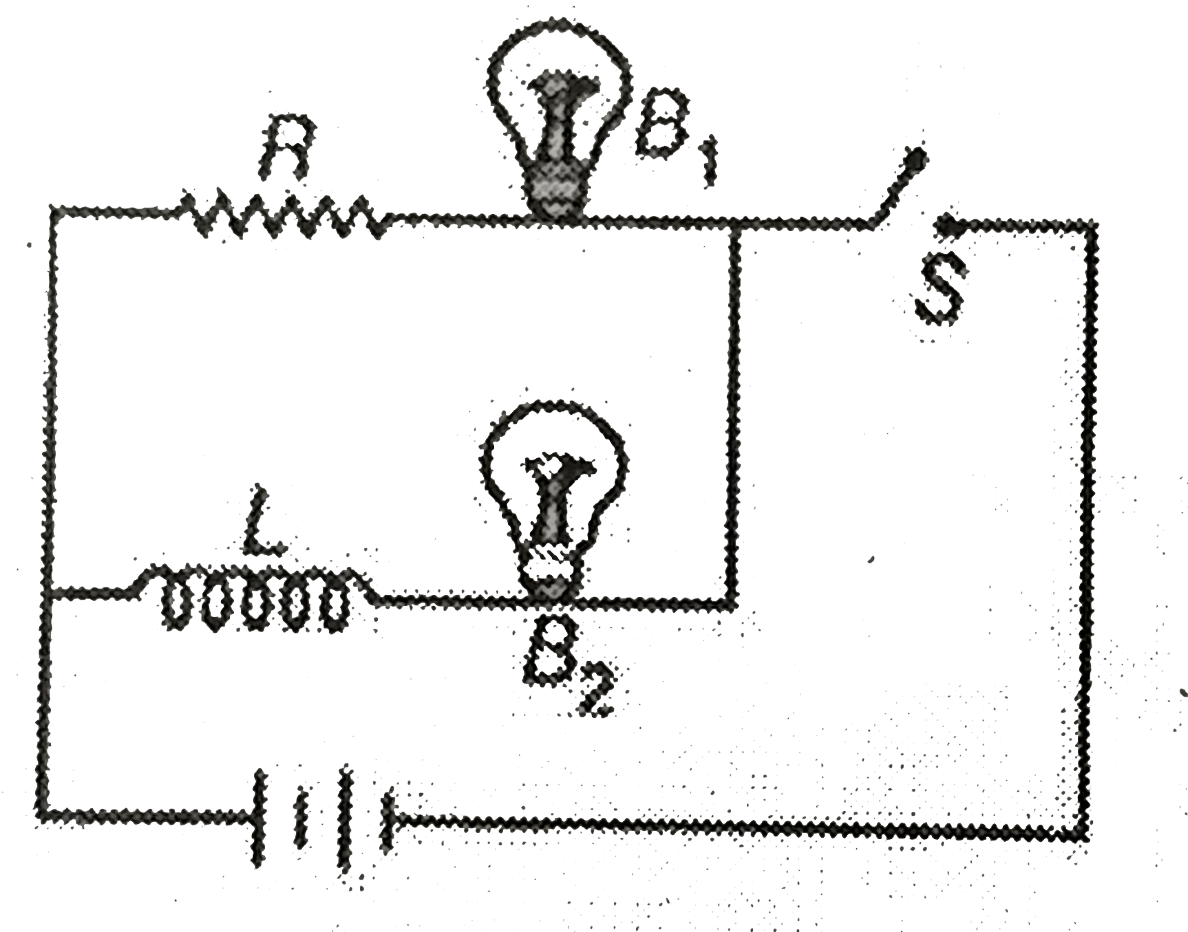 Aboth B1 and B2 die out promptlyBboth B1 and B2 die out with some selayCB1 dies out promptly but B2 with some selayDB_(2) dies out promptly but B1 with some delay
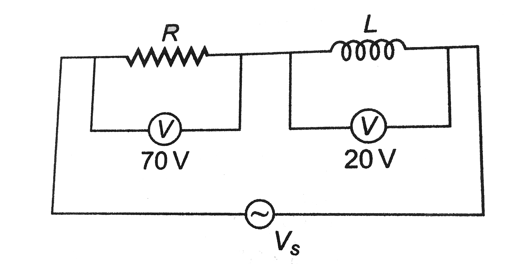
The adjoining figure shows an AC circuit with resistane R, inductance L and source voltage VS. Then
View SolutionThe given figure shows a circuit with a cell connected to a bulb and a switch.

When the switch is closed, the bulb lights up because the
View SolutionThe given figure shows a circuit with a cell connected to a bulb and a switch.
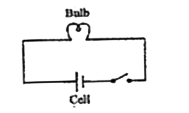
When the switch is closed, the bulb lights up because the
View SolutionFigure shows three idenetical bulbs A,B and C connected to a battery of supply voltage V. When the switch S is closed, discuss the change is .
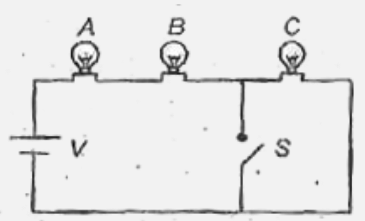
(a) The illumination of the three bulbs
(b) The power dissipated in the circuit .
View SolutionThe adjoining figure shows an AC circuit with resistance R, inductance L and source voltage VS. Then

View Solution

