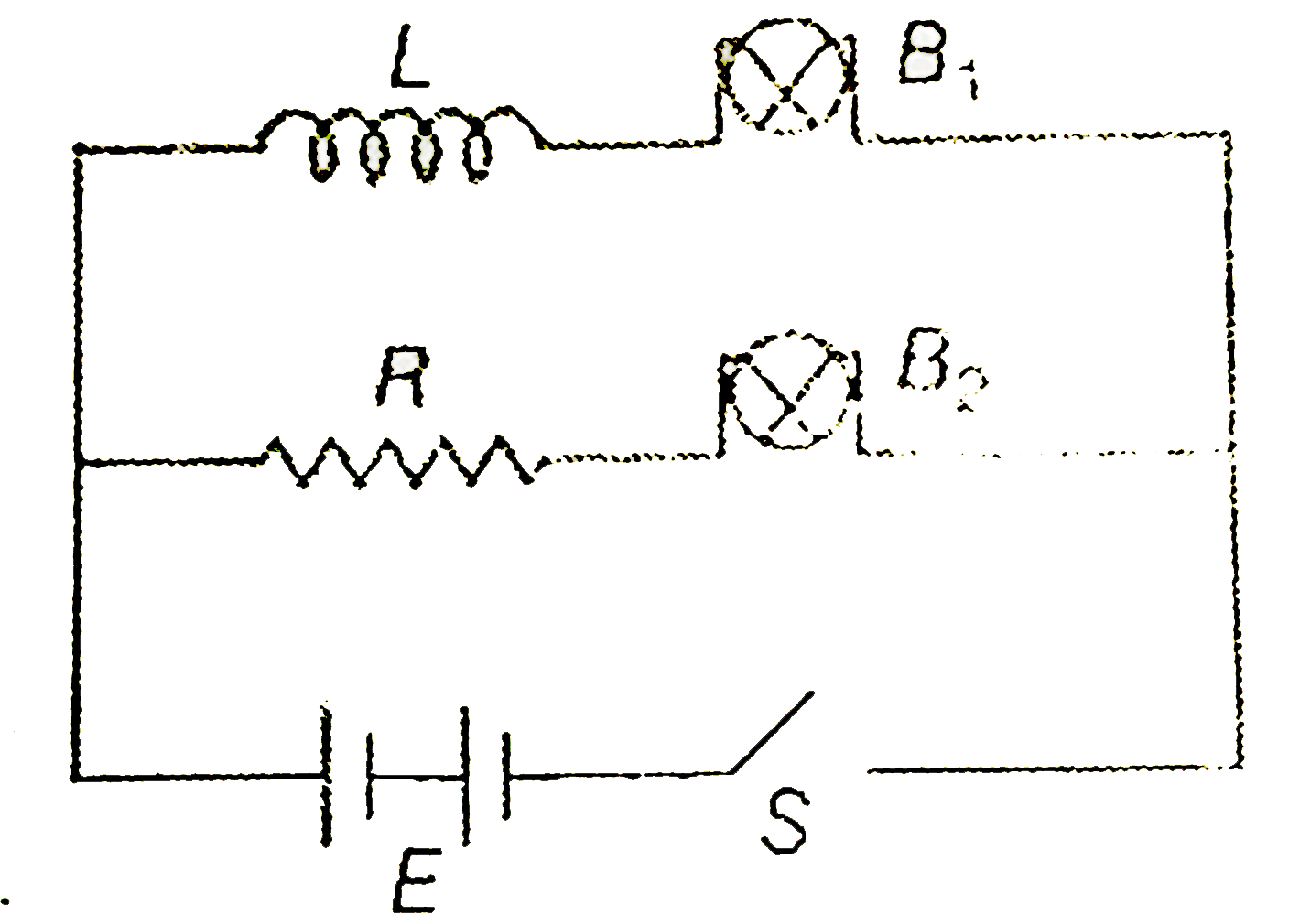
The adjoining figure shows two bulbs B1 and B2 resistor R and an inductor and L. When the switch S is turned off
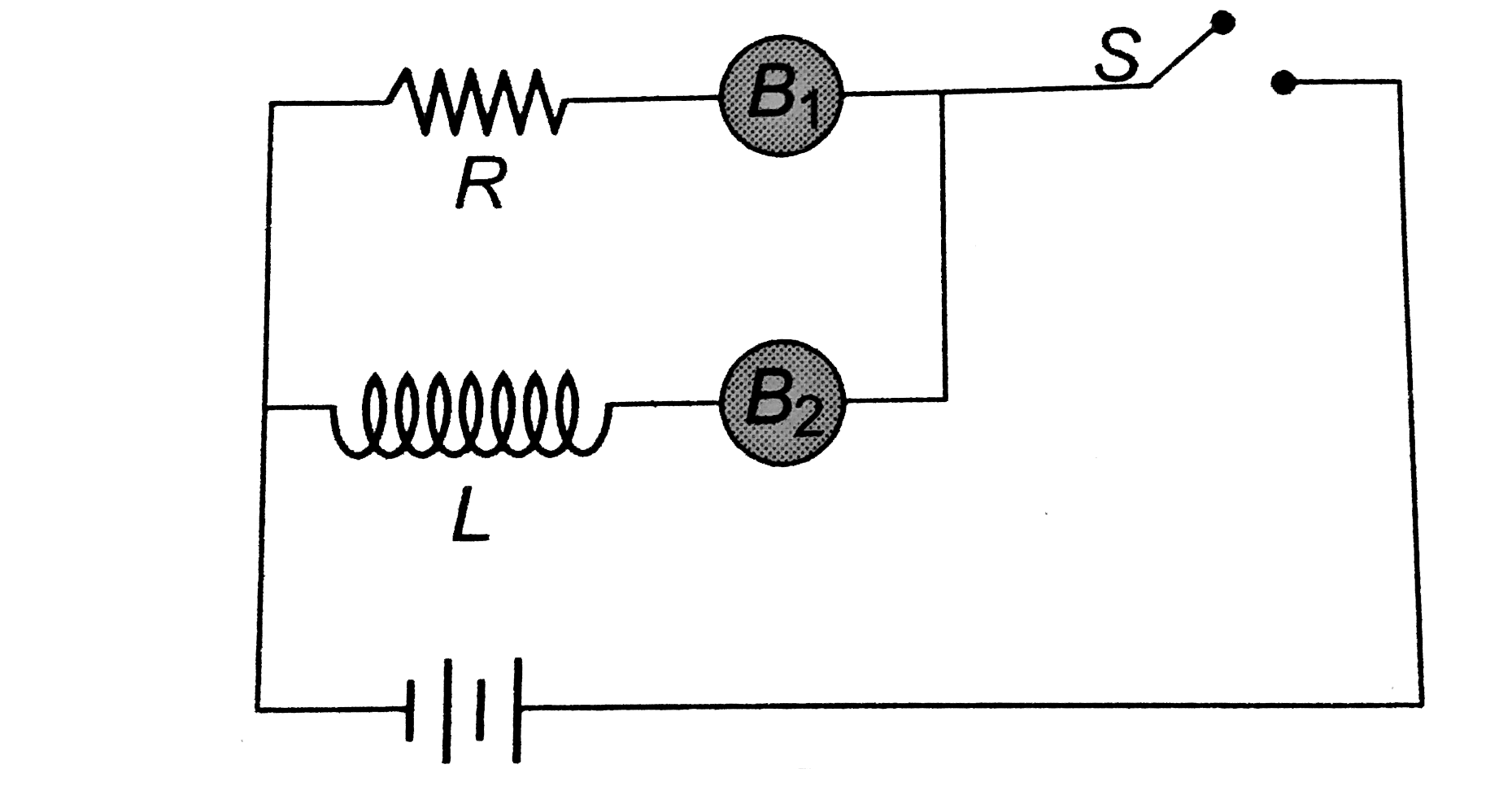
a. Both B1 and B2 die out promptly
b.Both B1 and B2 die out with some delay
c. B2 dies out promptly but B1 with some delay
d .B1 dies out promptly but B2 with some delay
The correct Answer is:C
Step by step video & image solution for The adjoining figure shows two bulbs B_(1) and B_(2) resistor R and an inductor and L. When the switch S is turned off by Physics experts to help you in doubts & scoring excellent marks in Class 12 exams.
Updated on:21/07/2023Topper's Solved these Questions
- ELECTROMAGNETIC INDUCTIONBOOK - DC PANDEY ENGLISHCHAPTER - ELECTROMAGNETIC INDUCTIONEXERCISE - Medical entrance special format questions
17 Videos
- ELECTROMAGNETIC INDUCTIONBOOK - DC PANDEY ENGLISHCHAPTER - ELECTROMAGNETIC INDUCTIONEXERCISE - Match the columns
5 Videos
- ELECTROMAGNETIC INDUCTIONBOOK - DC PANDEY ENGLISHCHAPTER - ELECTROMAGNETIC INDUCTIONEXERCISE - Check point
60 Videos
- CURRENT ELECTRICITYBOOK - DC PANDEY ENGLISHCHAPTER - CURRENT ELECTRICITYEXERCISE - Medical entrances gallery
97 Videos
- ELECTROMAGNETIC WAVESBOOK - DC PANDEY ENGLISHCHAPTER - ELECTROMAGNETIC WAVESEXERCISE - Sec C
22 Videos
Similar Questions
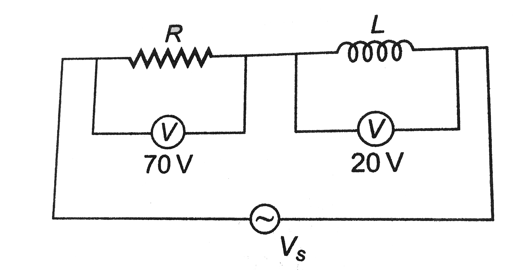
The adjoining figure shows an AC circuit with resistane R, inductance L and source voltage VS. Then
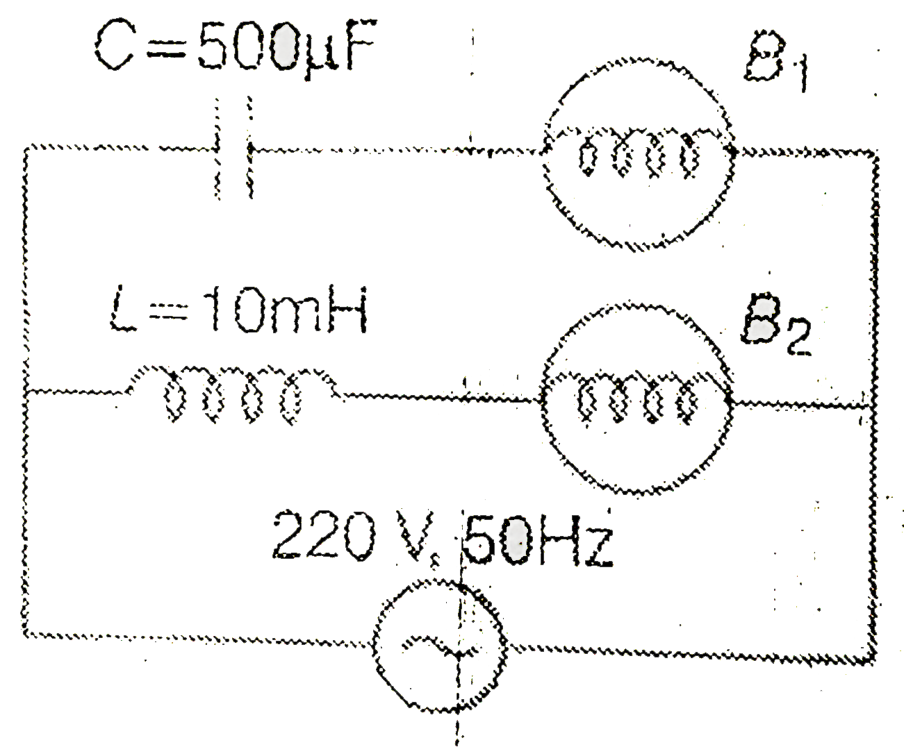
View SolutionIn the circuit shown in the figure, if both the bulbs B1andB2 are identical
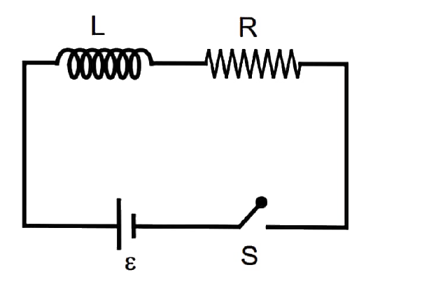
View SolutionThe figure below shows a battery of emf ε connected to an inductor L and resistance R in series. If the switch is closed at t=0, then the total charge that flows from the battery in time constant of the circuit is
View SolutionAn inductor L, a resistanc eR and two identical bulbs B1andB2 are connected to a battery through a switch S as shown in the figure . The resistance of coil having inductance L is also R. Which of the following statement gives the corrrect description of the happenings when the switch S is closed?
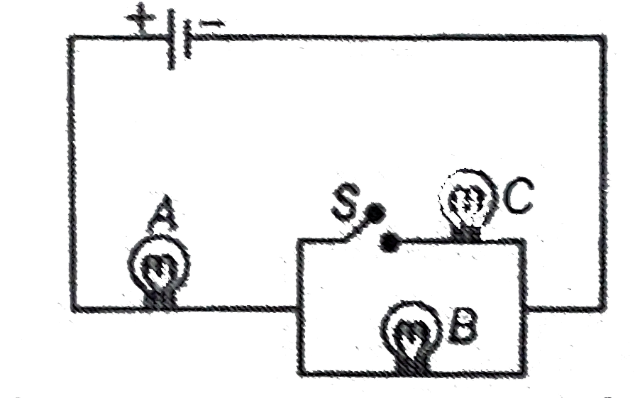
View SolutionA, B, C are identical bulbs. How does the brightness of A and B change when the switch S is closed ?
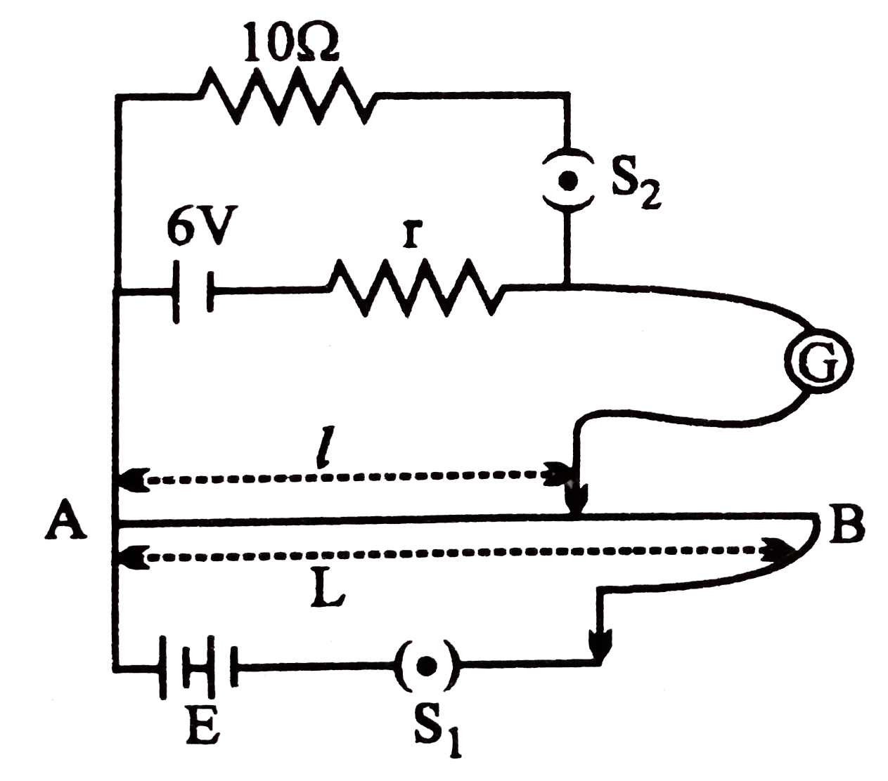
View SolutionIn the arrangement shown in figure when the switch S2 is open, the galvanometer shown no deflection for l=L/2. When the switch S2 is closed, the galvanometer shown no deflection for l=5L/12. The internal resistance (r) of 6V cell, and the emf E of the other battery are respectively
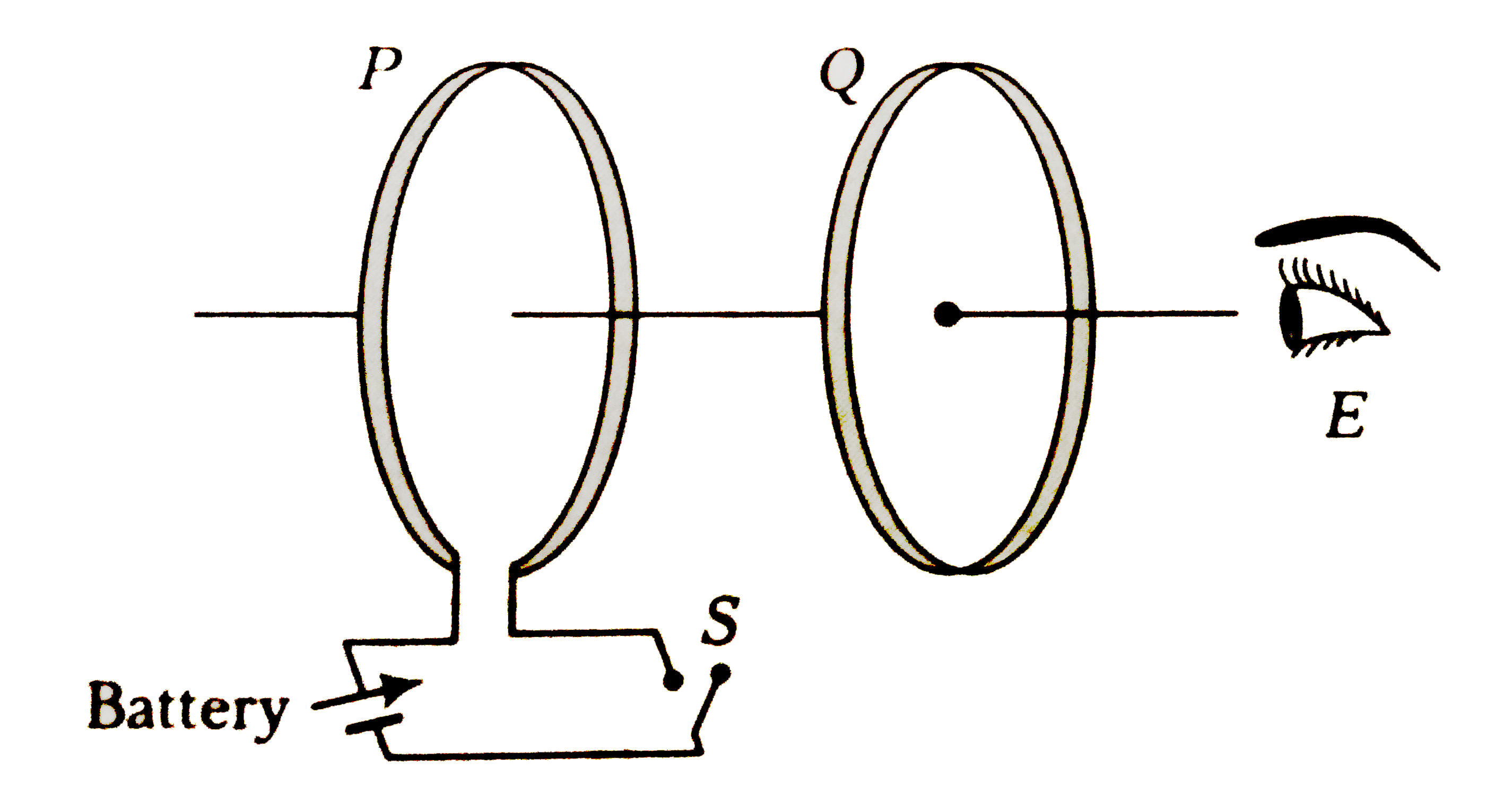
View SolutionAs shown in figure, P and Q are two co-axial conducting loops separated by some distance. When the switch S is closed, a clockwise current IP flows in P (as seen by E) and an induced current IQ1 flows in Q. The switch remains closed for a long time. When S is opened, a current IQ2 flows in Q.
Then, the directions of IQ1 and IQ2 (as seen by E) are
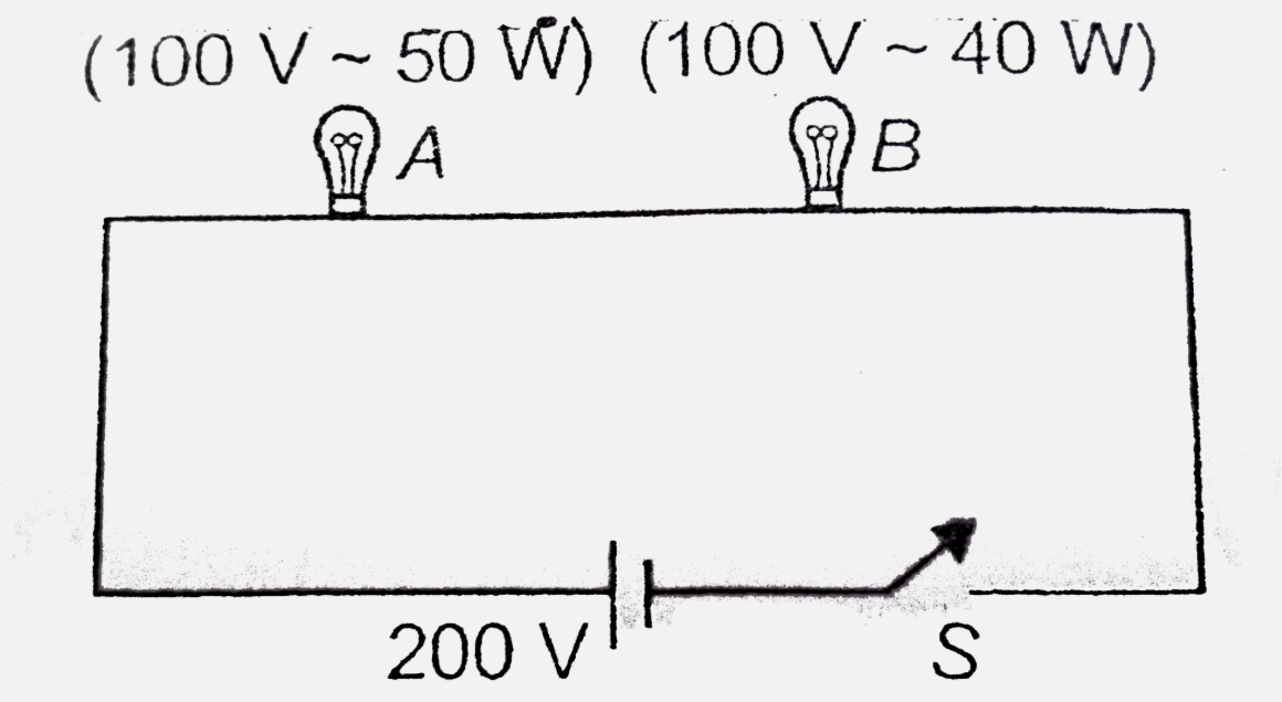
View SolutionTwo bulbs A and B are connected as shown . When switch 'S' is closed then which of them will fuse?
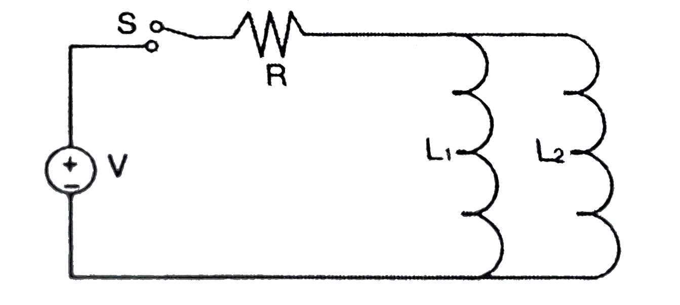
View SolutionA source of constant voltage V is connected to a resistance R and two ideal inductor L1andL2 through a switch S as shown. There is no mutual inducance between the two inductors. The swtich S is initially open. At t=0, the switch is closed and current begins to flow. Which of the following options is / are correct ?
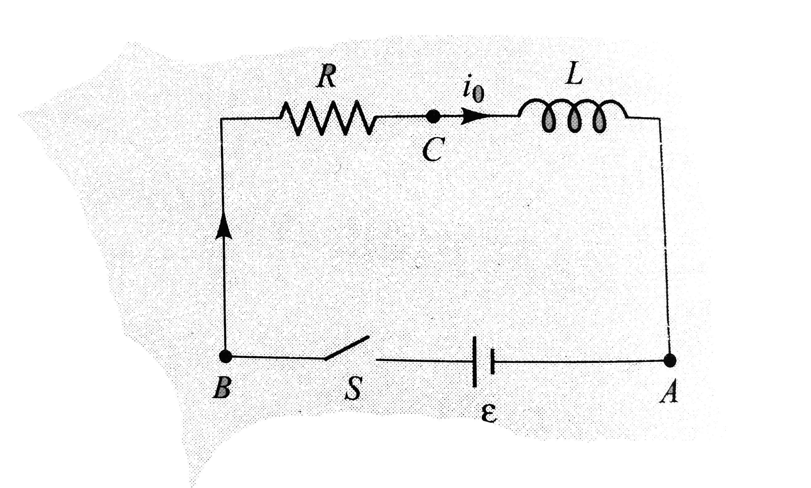
View SolutionFigure shows a circuit consisting of an ideal cell, an inductor L, and a resistor R, connected in series. Let switch S be closed at t=0. Suppose at t=0, the current in the inductor is io, then find out the equation of current as a function of time.
View Solution
