The adjoining figure shows two bulbs B1 and B2 resistor R and an inductor and L. When the switch S is turned off
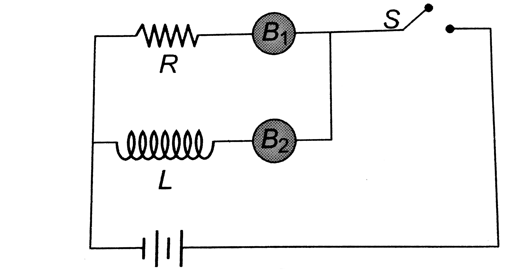
The bulb B2 lights up earlier than B1 and finally both the bulbs shine equally bright
B1 lights up earlier and finally both the bulbs acquire equal brightness
B2 lights up earlier and finally B1 shines brighter than B2
B1 and B2 light up together with equal brightness all the time
The correct Answer is:C
In L-R circuit current grows exponentially.
So, B2 lights up earlier and finally B1 shines brighter than B2.
Topper's Solved these Questions
- BOOK - DC PANDEY ENGLISHCHAPTER - ELECTROMAGNETIC INDUCTIONEXERCISE - Medical entrance special format questions17videos
ELECTROMAGNETIC INDUCTION
- BOOK - DC PANDEY ENGLISHCHAPTER - ELECTROMAGNETIC INDUCTIONEXERCISE - Match the columns5videos
ELECTROMAGNETIC INDUCTION
- BOOK - DC PANDEY ENGLISHCHAPTER - ELECTROMAGNETIC INDUCTIONEXERCISE - Check point60videos
ELECTROMAGNETIC INDUCTION
- BOOK - DC PANDEY ENGLISHCHAPTER - CURRENT ELECTRICITYEXERCISE - Medical entrances gallery97videos
CURRENT ELECTRICITY
- BOOK - DC PANDEY ENGLISHCHAPTER - ELECTROMAGNETIC WAVESEXERCISE - Sec C22videos
ELECTROMAGNETIC WAVES
Similar Questions
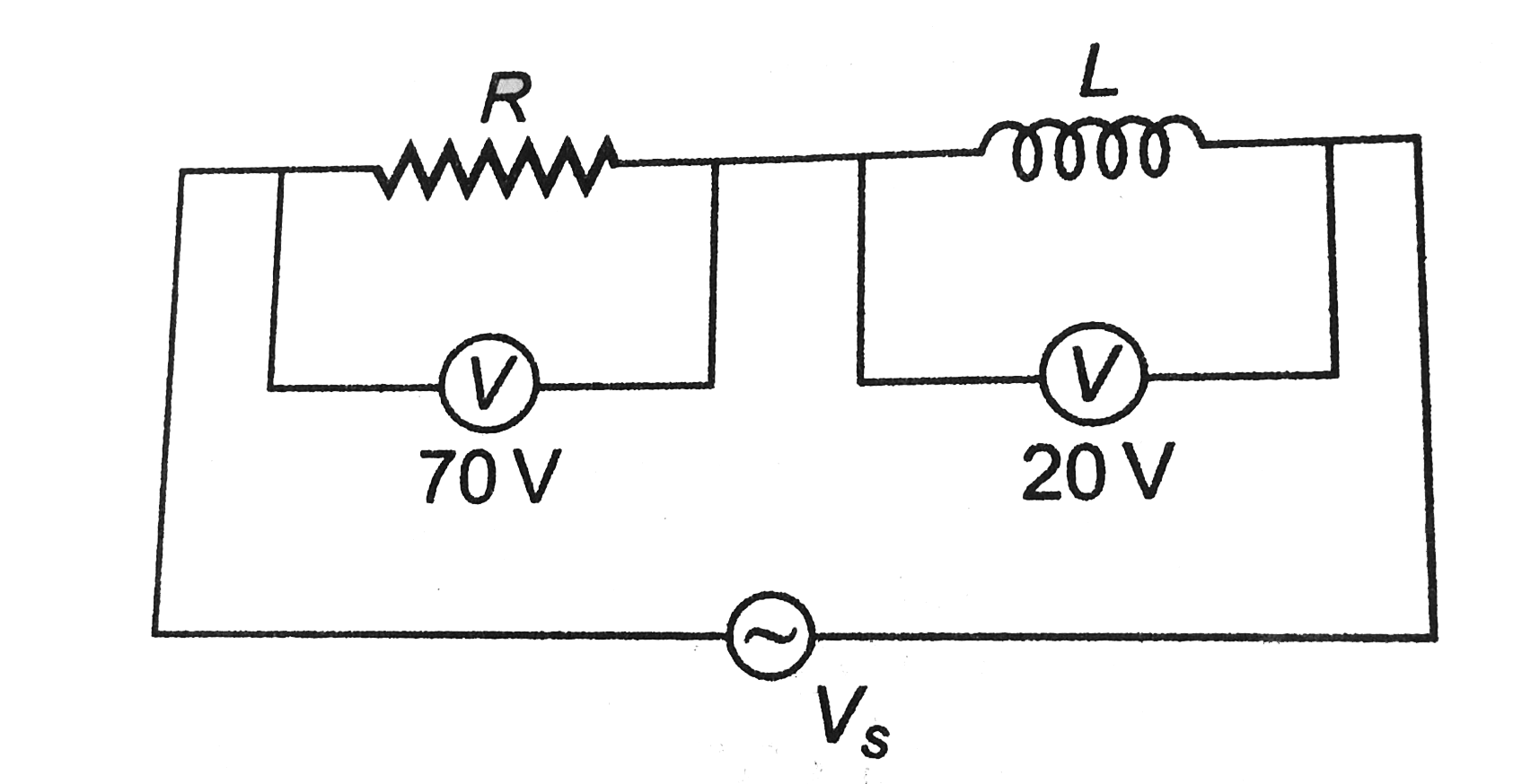
The adjoining figure shows an AC circuit with resistane R, inductance L and source voltage VS. Then
 View Solution
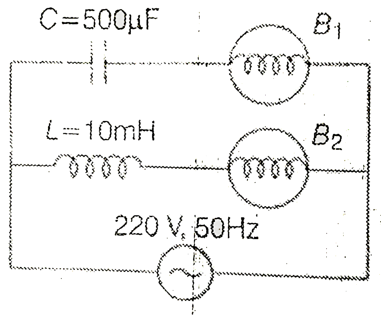
In the circuit shown in the figure, if both the bulbs B1andB2 are identical
 View Solution
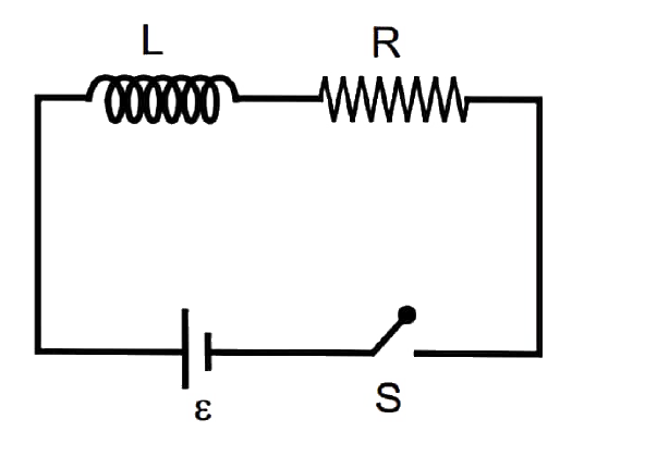
The figure below shows a battery of emf ε connected to an inductor L and resistance R in series. If the switch is closed at t=0, then the total charge that flows from the battery in time constant of the circuit is
 View Solution
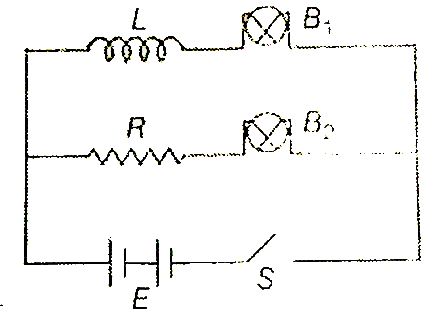
An inductor L, a resistanc eR and two identical bulbs B1andB2 are connected to a battery through a switch S as shown in the figure . The resistance of coil having inductance L is also R. Which of the following statement gives the corrrect description of the happenings when the switch S is closed?
 View Solution
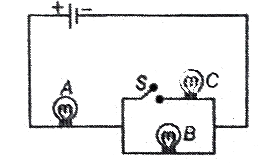
A, B, C are identical bulbs. How does the brightness of A and B change when the switch S is closed ?
 View Solution
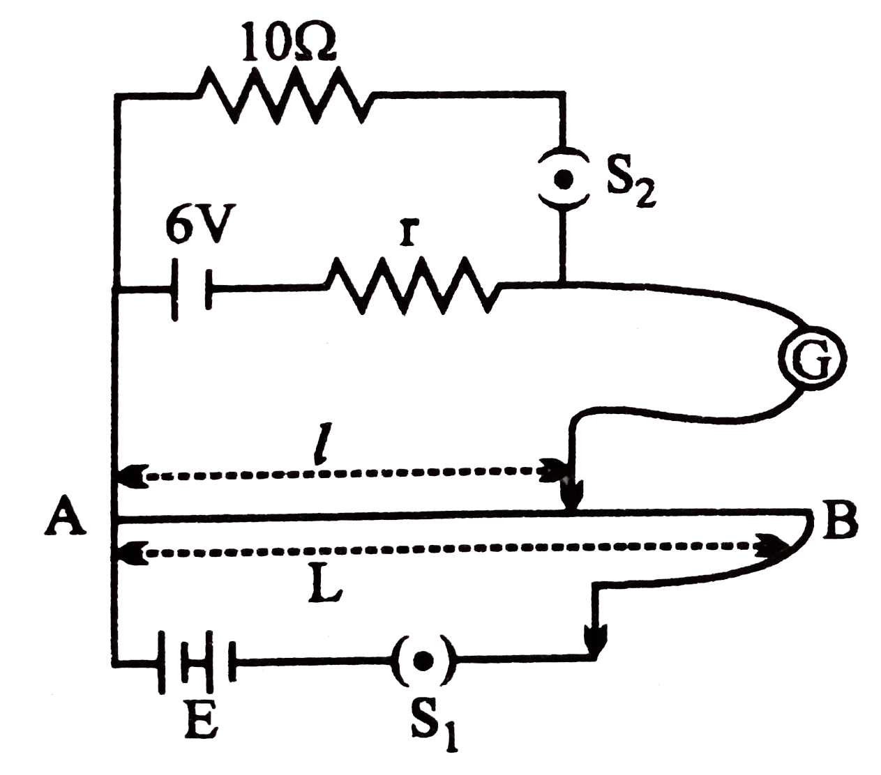
In the arrangement shown in figure when the switch S2 is open, the galvanometer shown no deflection for l=L/2. When the switch S2 is closed, the galvanometer shown no deflection for l=5L/12. The internal resistance (r) of 6V cell, and the emf E of the other battery are respectively
 View Solution
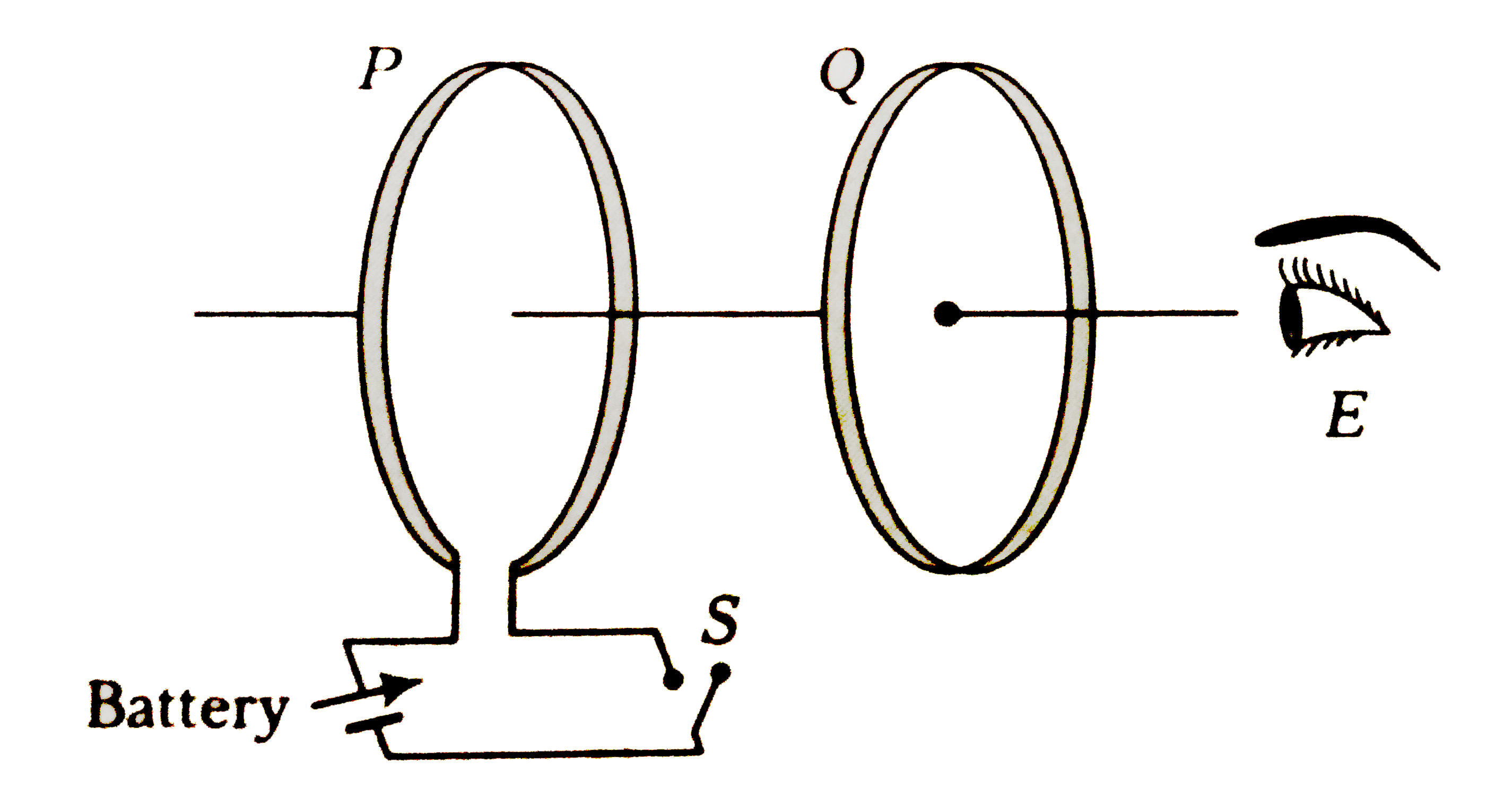
As shown in figure, P and Q are two co-axial conducting loops separated by some distance. When the switch S is closed, a clockwise current IP flows in P (as seen by E) and an induced current IQ1 flows in Q. The switch remains closed for a long time. When S is opened, a current IQ2 flows in Q.
Then, the directions of IQ1 and IQ2 (as seen by E) are
 View Solution
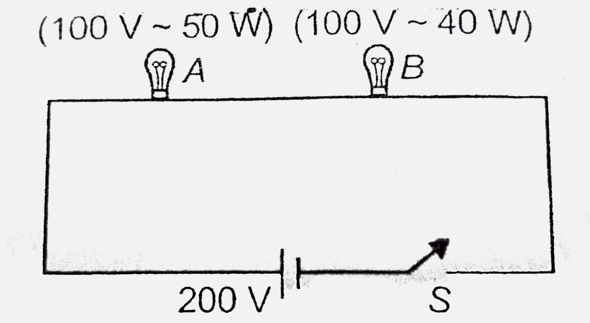
Two bulbs A and B are connected as shown . When switch 'S' is closed then which of them will fuse?
 View Solution
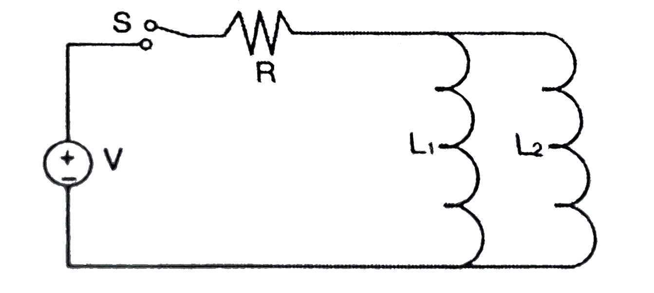
A source of constant voltage V is connected to a resistance R and two ideal inductor L1andL2 through a switch S as shown. There is no mutual inducance between the two inductors. The swtich S is initially open. At t=0, the switch is closed and current begins to flow. Which of the following options is / are correct ?
 View Solution
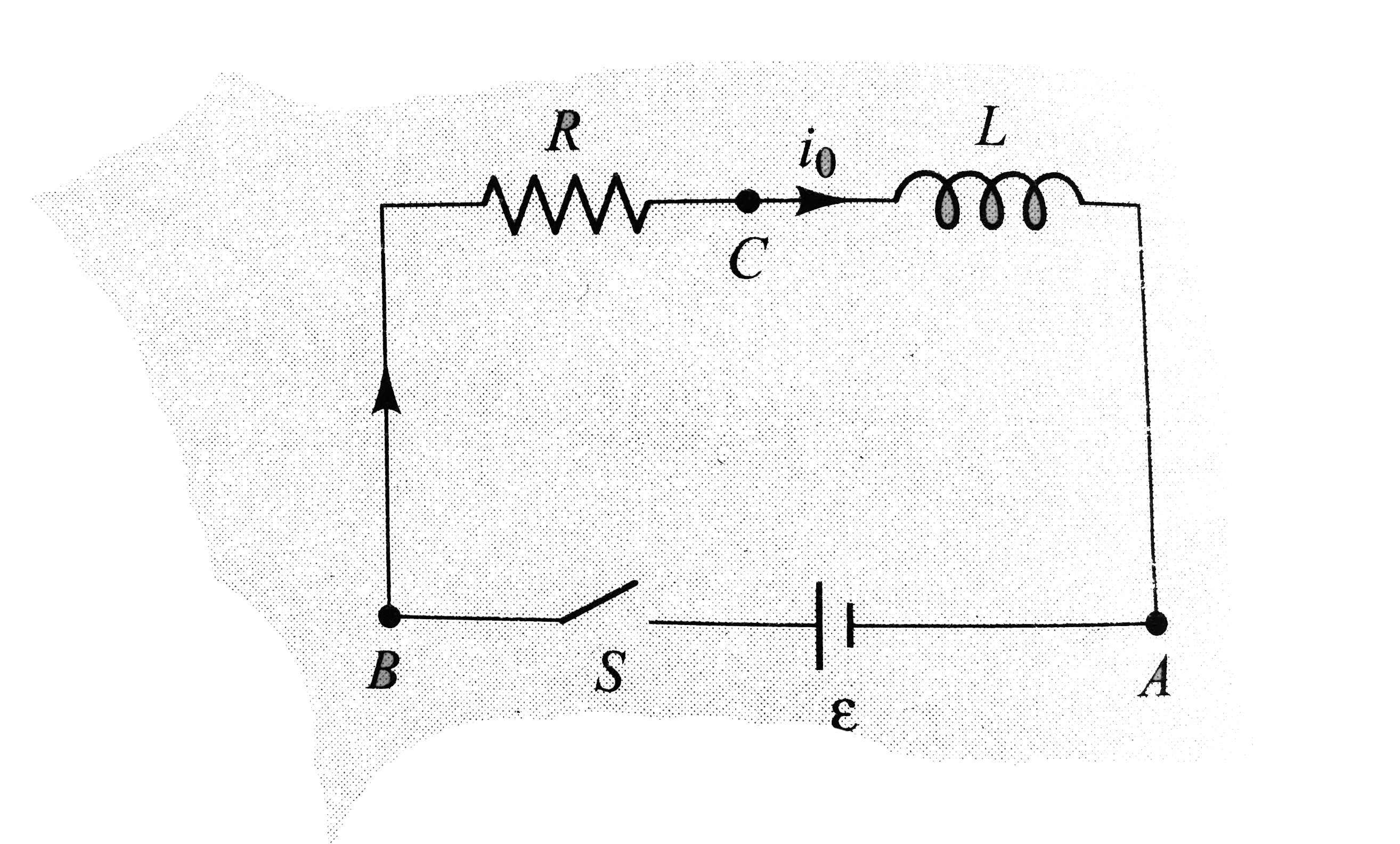
Figure shows a circuit consisting of an ideal cell, an inductor L, and a resistor R, connected in series. Let switch S be closed at t=0. Suppose at t=0, the current in the inductor is io, then find out the equation of current as a function of time.
 View Solution

