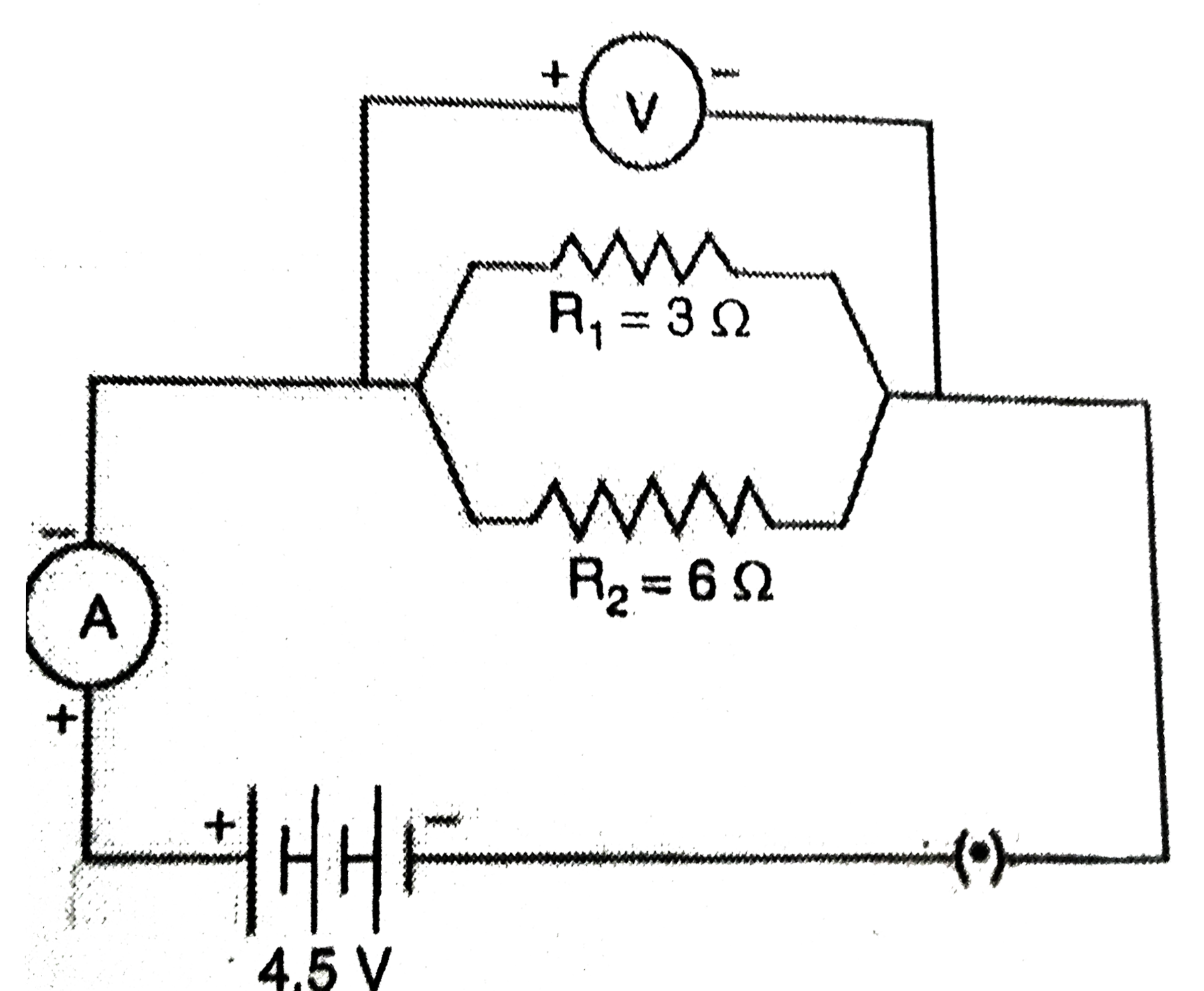
The ammeter, voltmeter and, resistors R1 and R2 connected in the circuit as shown below have been checked and found to be correct.
On plugging the key, the voltmeter reads 4.5 V but the ammeter reads 1.5 A. This is most likely because the wires joined to :
A
resistor R1 are loose
B
resistor R2 are loose
C
both the resistors R1 and R2 are loose
D
ammeter terminals are loose
Video Solution
Text Solution
The correct Answer is:B
NA
|
Topper's Solved these Questions
- THE HUMAN EYE AND THE COLOURFUL WORLD BOOK - LAKHMIR SINGH & MANJIT KAURCHAPTER - THE HUMAN EYE AND THE COLOURFUL WORLD EXERCISE - Long Answer Type Question
3 Videos
- THE HUMAN EYE AND THE COLOURFUL WORLD BOOK - LAKHMIR SINGH & MANJIT KAURCHAPTER - THE HUMAN EYE AND THE COLOURFUL WORLD EXERCISE - NCERT Book
14 Videos
- THE HUMAN EYE AND THE COLOURFUL WORLD BOOK - LAKHMIR SINGH & MANJIT KAURCHAPTER - THE HUMAN EYE AND THE COLOURFUL WORLD EXERCISE - Long Answer Type Questions
2 Videos
- TEST PAPER 4BOOK - LAKHMIR SINGH & MANJIT KAURCHAPTER - TEST PAPER 4EXERCISE - SECTION A
10 Videos
Similar Questions
Knowledge Check
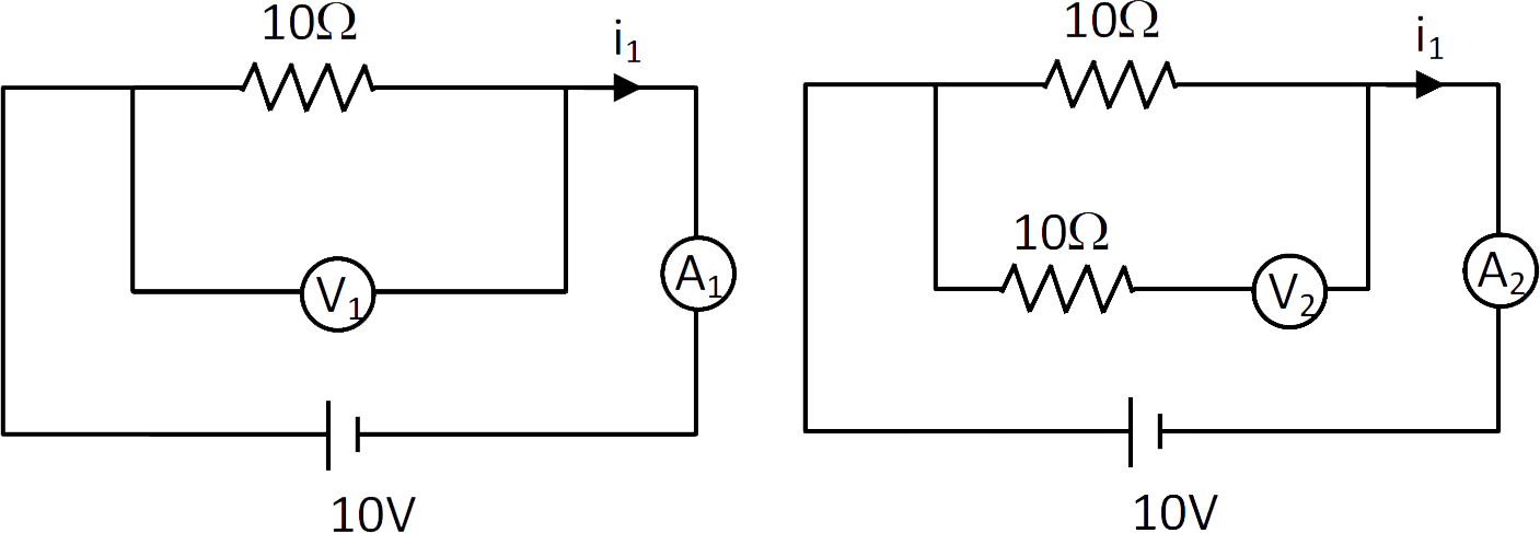
In the circuits shown below, the readings of the voltmeters and the ammeters will be
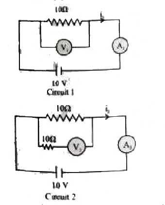 AV2>V1andi1=i2BV1=V2andi1>i2Cv1=V2andi1=i2DV2>V1andi1>i2
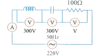
In the circuit shown below, what will be the reading of the voltmeter and ammeter?
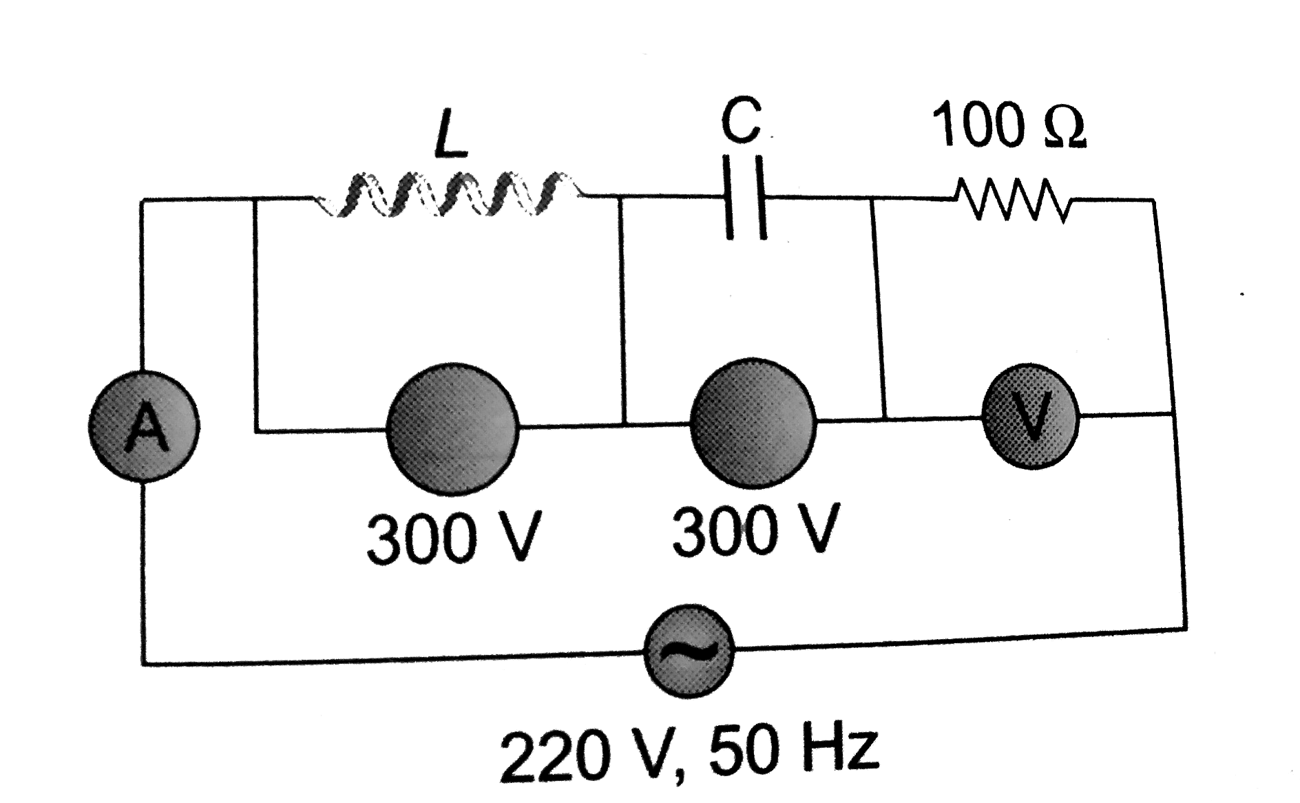 A800V,2AB300V,2AC220V,2.2AD100V,2A
An ammeter, voltmeter and a resistor are connected in series to a cell and the readings are noted as I and V. If another resistor R is connected in parallel with a voltmeter, then
AI and V increaseBI increasesCI and V will remain sameDI decreases
In the circuit shown in Fig. 4.25, the voltmeter reads 1.5 V, when the key is open. When the key is closed, the voltmeter reads 1.35 V and ammeter reads 1.5 A. Find the emf and the internal resistance of the cell.
View SolutionIn the series LCR circuit as shown in the figure, the voltmeter V and ammeter A reading are
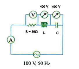
View SolutionIn the series LCR circuit as shown in the figure, the voltmeter V and ammeter A reading are

View SolutionIn the circuits shown below, the readings of the voltmeters and the ammeters will be:
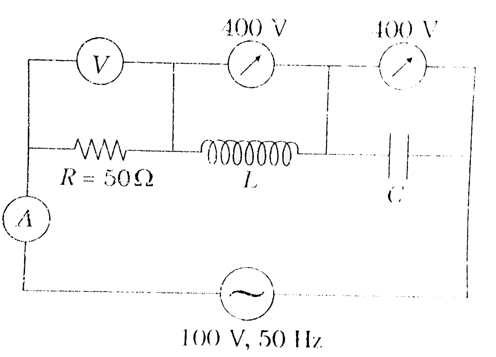
View SolutionIn the series L-C-R circuit , the voltmeter and ammeter readings are
View Solution

