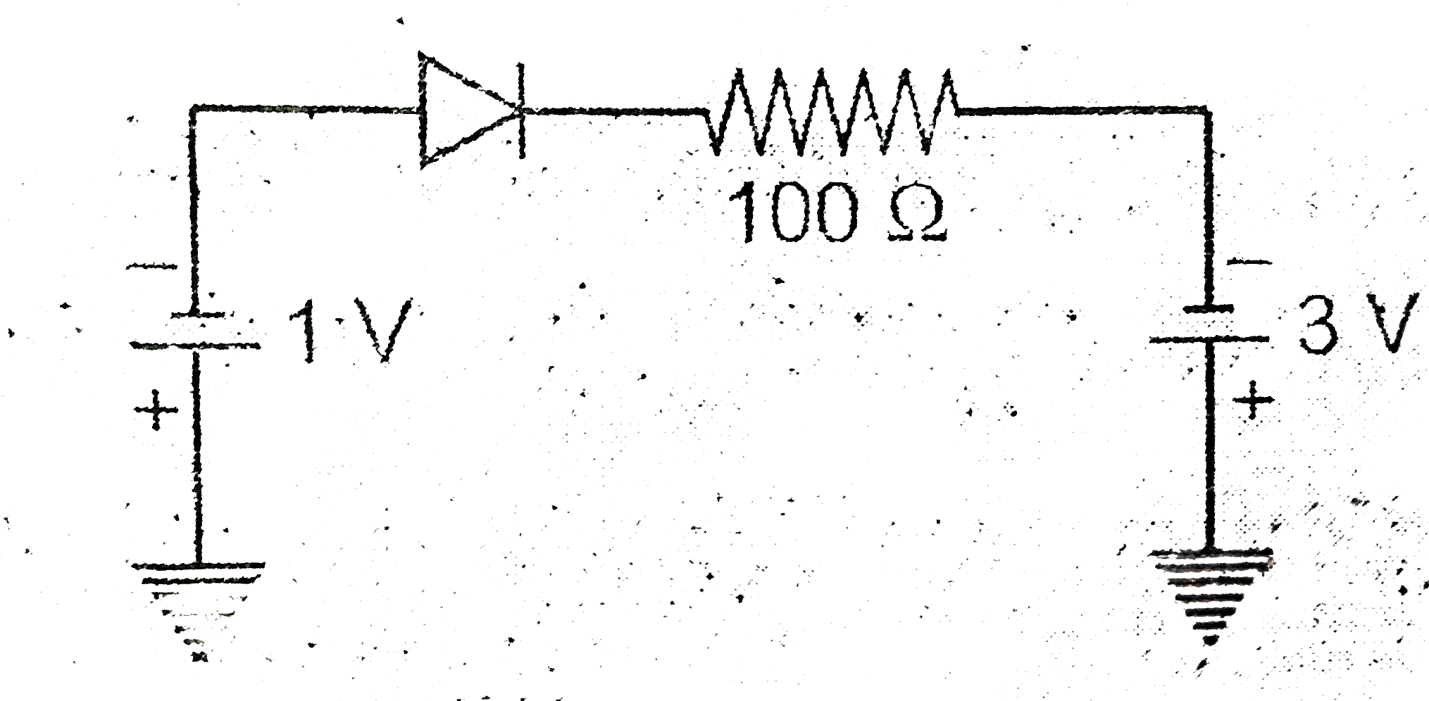
The barrier potential in an ideal P-n junction diode is 0.3 volts. The current required is 6 mA. If a resistance of is connected in series with the junction diode, then the emf of the cell required for use in the circuit is
0.3 V
1.2 V
0.9 V
1.5 V
The correct Answer is:D
To solve the problem, we need to find the electromotive force (emf) required for the circuit with a P-N junction diode, given the barrier potential, current, and resistance in the circuit.
1. Identify the Given Values:
- Barrier potential (V_d) = 0.3 V
- Current (I) = 6 mA = 0.006 A (conversion from milliamperes to amperes)
- Resistance (R) = 200 Ω
2. Use the Formula for EMF:
The relationship between emf (E), barrier potential (V_d), current (I), and resistance (R) in a series circuit can be expressed as:
E=Vd+I⋅R
3. Calculate the Voltage Drop Across the Resistor:
First, we need to calculate the voltage drop across the resistor using Ohm's Law (V = I * R):
VR=I⋅R=0.006A⋅200Ω=1.2V
4. Substitute the Values into the EMF Formula:
Now, substitute V_d and V_R into the EMF formula:
E=Vd+VR=0.3V+1.2V
5. Calculate the Total EMF:
E=0.3+1.2=1.5V
6. Conclusion:
The required emf of the cell for use in the circuit is 1.5 V.
Final Answer:
The emf required is 1.5 volts.
---
- Barrier potential (V_d) = 0.3 V
- Current (I) = 6 mA = 0.006 A (conversion from milliamperes to amperes)
- Resistance (R) = 200 Ω
The relationship between emf (E), barrier potential (V_d), current (I), and resistance (R) in a series circuit can be expressed as:
E=Vd+I⋅R
First, we need to calculate the voltage drop across the resistor using Ohm's Law (V = I * R):
VR=I⋅R=0.006A⋅200Ω=1.2V
Now, substitute V_d and V_R into the EMF formula:
E=Vd+VR=0.3V+1.2V
E=0.3+1.2=1.5V
The required emf of the cell for use in the circuit is 1.5 V.
The emf required is 1.5 volts.
Topper's Solved these Questions
- SEMICONDUCTOR DEVICESBOOK - AAKASH SERIESCHAPTER - SEMICONDUCTOR DEVICESEXERCISE - PRACTICE EXERCISE (TRANSISTORS )
8 Videos
- SEMICONDUCTOR DEVICESBOOK - AAKASH SERIESCHAPTER - SEMICONDUCTOR DEVICESEXERCISE - PRACTICE EXERCISE (LOGIC GATES )
15 Videos
- SEMICONDUCTOR DEVICESBOOK - AAKASH SERIESCHAPTER - SEMICONDUCTOR DEVICESEXERCISE - EXERCISE -II (LOGIC GATES)
12 Videos
- RAY OPTICSBOOK - AAKASH SERIESCHAPTER - RAY OPTICSEXERCISE - PROBLEMS ( LEVEL-II)
60 Videos
- UNITS AND MEASUREMENTBOOK - AAKASH SERIESCHAPTER - UNITS AND MEASUREMENTEXERCISE - PRACTICE EXERCISE
45 Videos
Similar Questions
Knowledge Check
In a p−n junction diode, the barrier potential opposes diffusion of
Aminority carrier in both regions onlyBmajority carriers onlyCelectrons in p regionDholes in p region
p−n junction diode can be used as
View SolutionConsider the junction diode is ideal. The value of current through the resistance of 200Ω is

View SolutionConsider the junction diode is ideal. The value of current through the resistance of 300Ω is

View SolutionThe resistance of a reverse baised P-N junction diode is about-
View SolutionWhat is the current through an ideal p-n junction diode shown in figure below ?

View SolutionIn a arrangement, 3n cells of emf ε and internal resistance r are connected in series. Out of 3n cells polarity of n cells is reversed. Current in the circuit is

View SolutionIn forward bias, the width of potential barrier in a P−N junction diode
View Solution
