The circuit as shown in the figure is equivalent to
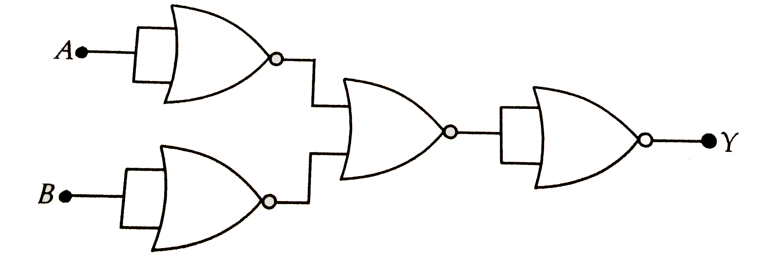
AND gate
NOT gate
OR gate
NAND gate
The correct Answer is:D
Step by step video, text & image solution for The circuit as shown in the figure is equivalent to by Physics experts to help you in doubts & scoring excellent marks in Class 12 exams.
Updated on:21/07/2023Topper's Solved these Questions
- PRACTICE PAPPERBook:NCERT FINGERTPS ENGLISHChapter:PRACTICE PAPPERExercise:Practice Papper 2
Explore 50 Videos
- PRACTICE PAPPERBook:NCERT FINGERTPS ENGLISHChapter:PRACTICE PAPPERExercise:Practice Papper 3
Explore 50 Videos
- NUCLEIBook:NCERT FINGERTPS ENGLISHChapter:NUCLEIExercise:Assertion And Reason
Explore 15 Videos
- RAY OPTICS AND OPTICAL INSTRUMENTSBook:NCERT FINGERTPS ENGLISHChapter:RAY OPTICS AND OPTICAL INSTRUMENTSExercise:NCERT Exemplar
Explore 11 Videos
Similar Questions
The circuit shown in the figure acts as

View SolutionIn the circuit shown in the figure,
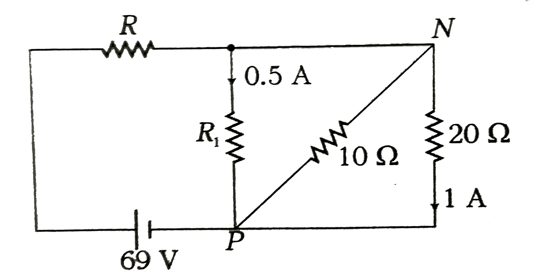
View SolutionFor the circuit shown in the figure
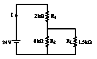
View SolutionFor the circuit shown in the figure
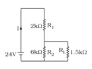
View SolutionIn the circuit shown in the figure
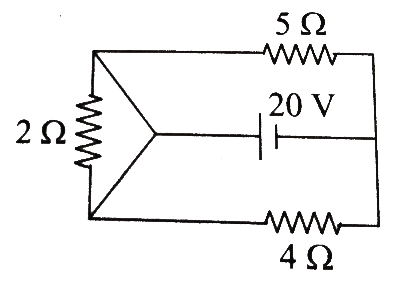 .
.
View SolutionFor the circuit shown in the figure :
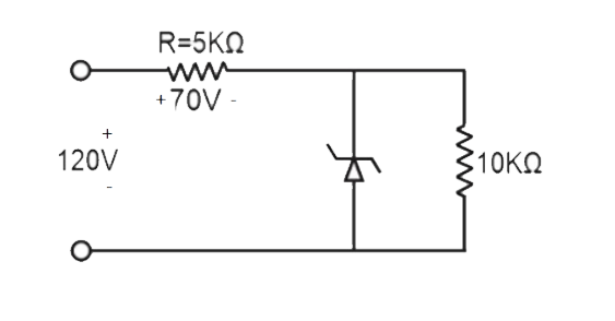
View SolutionIn LCR circuit as shown in figure
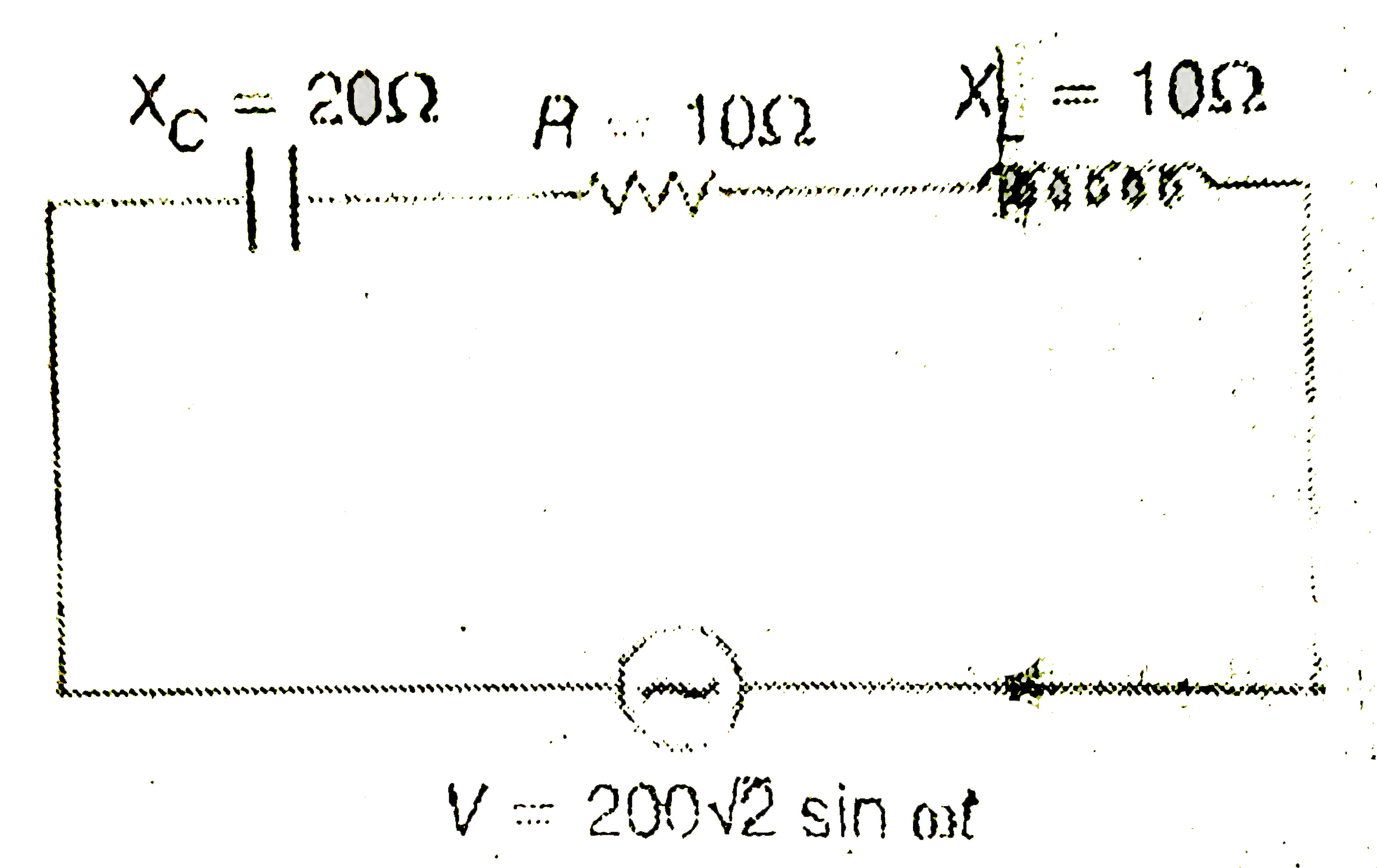
View SolutionConsider the circuit as shown in figure. The equivalent resistance between A and B is
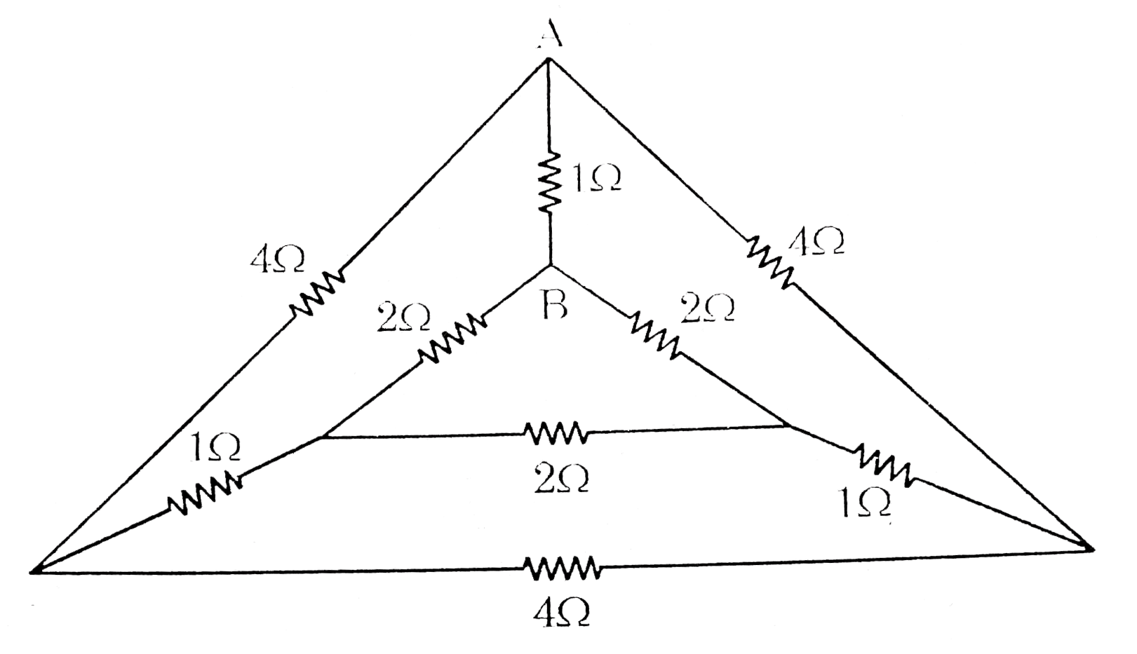
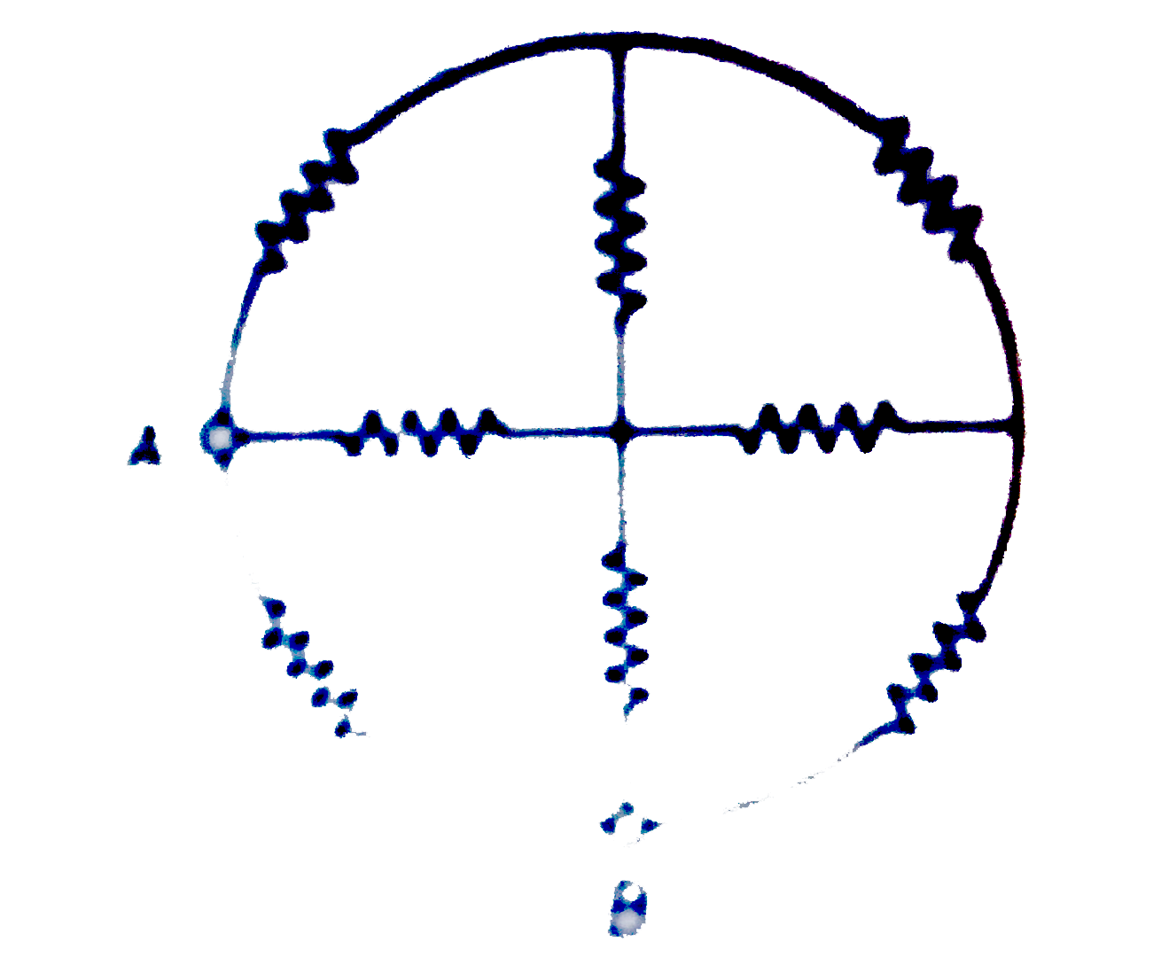
View SolutionEight resistances each of resistance 5Ω are connected in the circuit as shown in figure. The equivalent resistance between A and B is
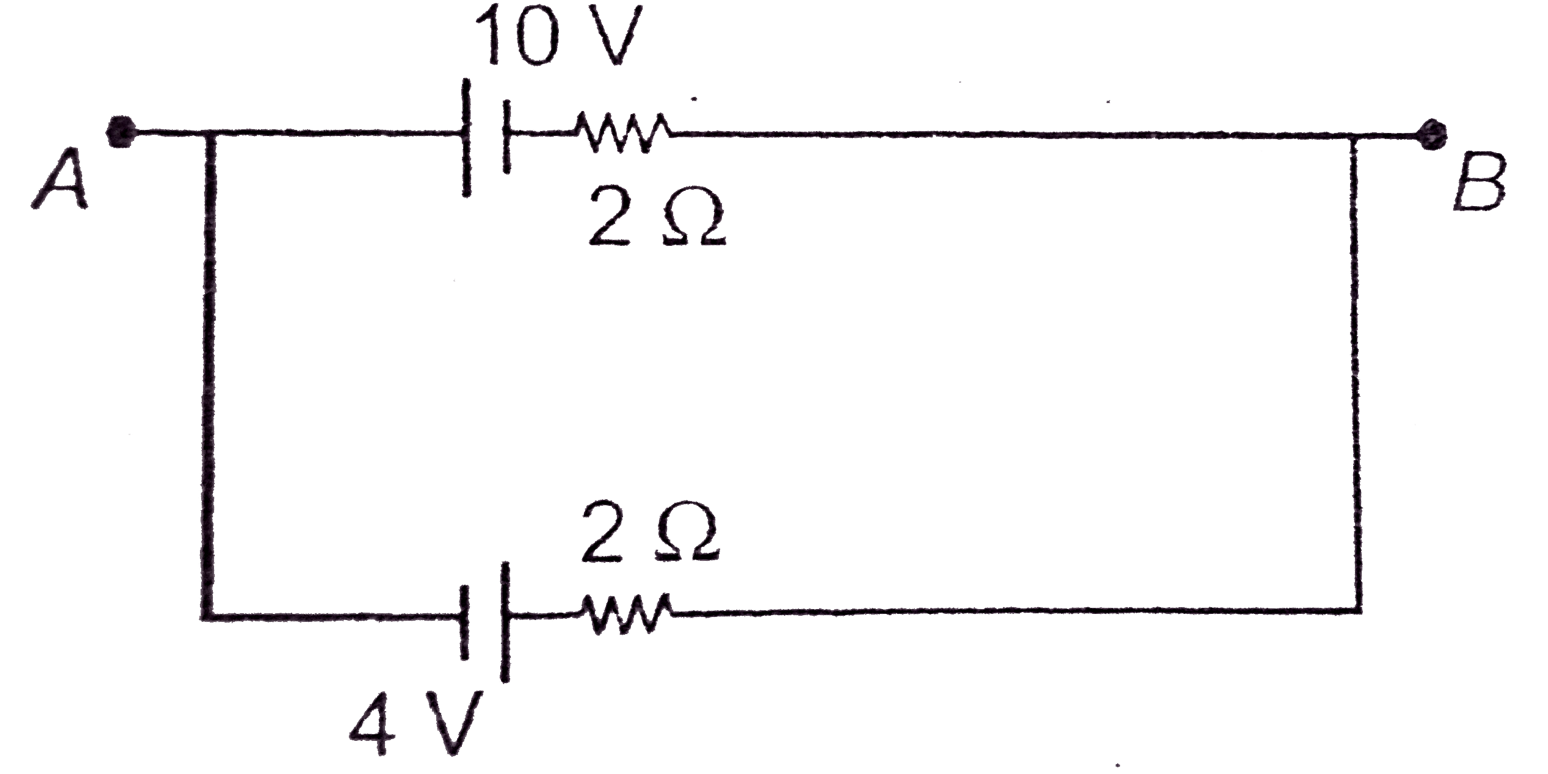
View SolutionThe situation shown in figure is equivalent to
View Solution