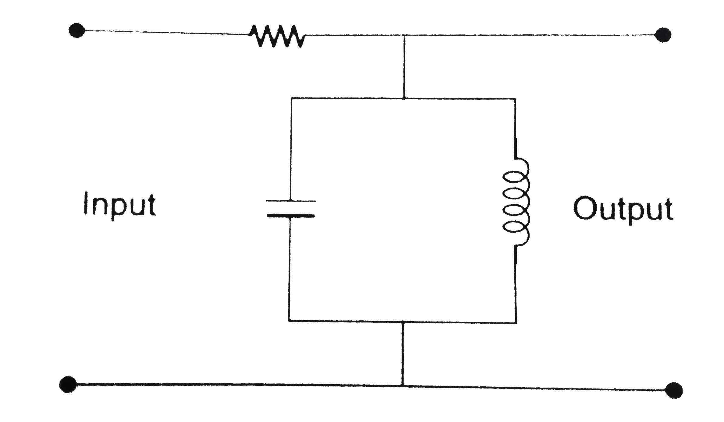
The circuit shown below acts as
A
high pass filter
B
low pass filter
C
tuned filter
D
rectifier
Text Solution
The correct Answer is:C
The circuit is tuned filter circuit. It utilizes one or more tuned circuits (resonant or anti-resonant circuits) to separte signals in relatively narrow bands of frequencies from signal wider frequency spectrums. Most transmitters and recievers incorporate many tuned filters. The give LCR tuned filter (also known as RLC tuned fillter) is the most flexible of alll frequency or frequency non-linear circuits. It is preferred for its frequency selection property.
|
Topper's Solved these Questions
- SEMICONDUCTOR ELECTRONICSBOOK - A2ZCHAPTER - SEMICONDUCTOR ELECTRONICSEXERCISE - Assertion Reason
18 Videos
- SEMICONDUCTOR ELECTRONICSBOOK - A2ZCHAPTER - SEMICONDUCTOR ELECTRONICSEXERCISE - SECTION -D
1 Videos
- SEMICONDUCTOR ELECTRONICSBOOK - A2ZCHAPTER - SEMICONDUCTOR ELECTRONICSEXERCISE - AIPMT/NEET Questions
77 Videos
- NUCLEAR PHYSICSBOOK - A2ZCHAPTER - NUCLEAR PHYSICSEXERCISE - Section D - Chapter End Test
29 Videos
- SOURCE AND EFFECT OF MAGNETIC FIELDBOOK - A2ZCHAPTER - SOURCE AND EFFECT OF MAGNETIC FIELDEXERCISE - Section D - Chapter End Test
30 Videos
Similar Questions
Knowledge Check
The circuit shown below will act as
 AAND gateBOR gateCNAND gateDXOR gate
In the circuit shown below, what is the equivalent resistance ?
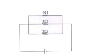 A11ΩB4ΩC1ΩD3Ω
A circuit is shown below.
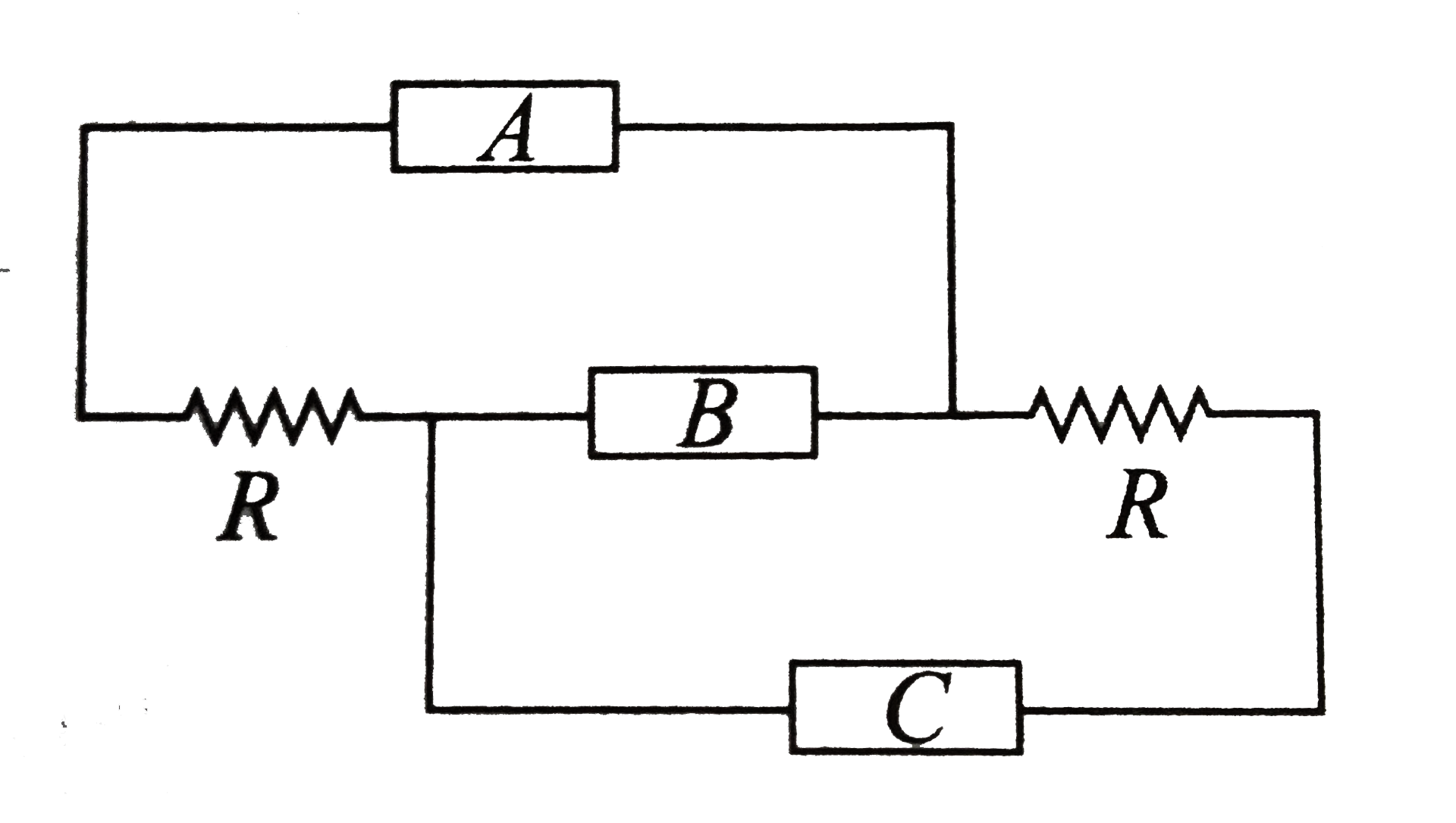 AIf A is an ideal ammeter, B an ideal battery of voltage V, and C an ideal voltmeter, the ratio reading of C/ reading of A is R.BIf A is a capacitor, B an ideal ammeter and C an ideal battery of voltage V, the potential difference across the capacitor is zero.CIf A is an ideal ammeter, B an ideal battery of voltage of V, and C an ideal voltmeter, the ratio reading of C/reading of A isR/2DIf A is a capacitor, B an ideal ammeter, and C an ideal battery of voltage V, the potential difference across the capacitor is 2 V.
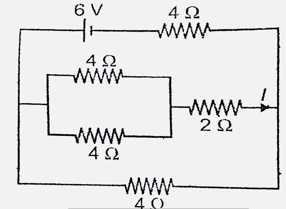
The current I in the circuit shown below is
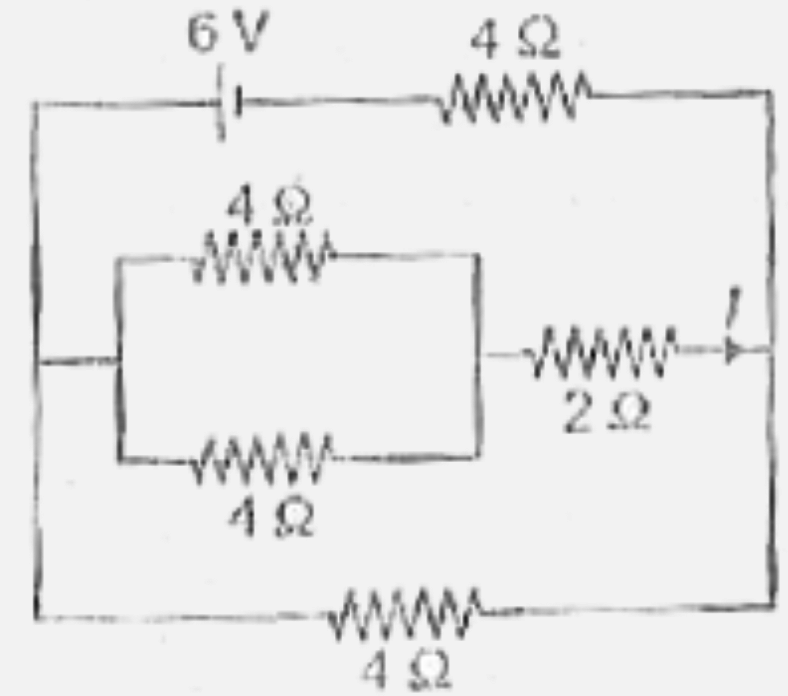
View SolutionThe power factor for the circuit shown below is
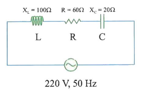
View SolutionThe power factor for the circuit shown below is

View SolutionIn the circuit shown below, calculate the total resistance of the circuit and the current flowing through it.
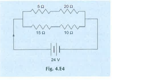
View SolutionFor the circuit shown below, calculate the value of Iz :
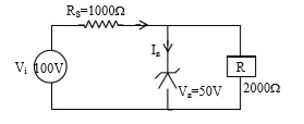
View Solution

