The circuit shown in Fig. is switched on at t = 0. Calculate the time at which current in R2 becomes half the steady value of current. Also, calculate the energy stored in the inductor at that time.
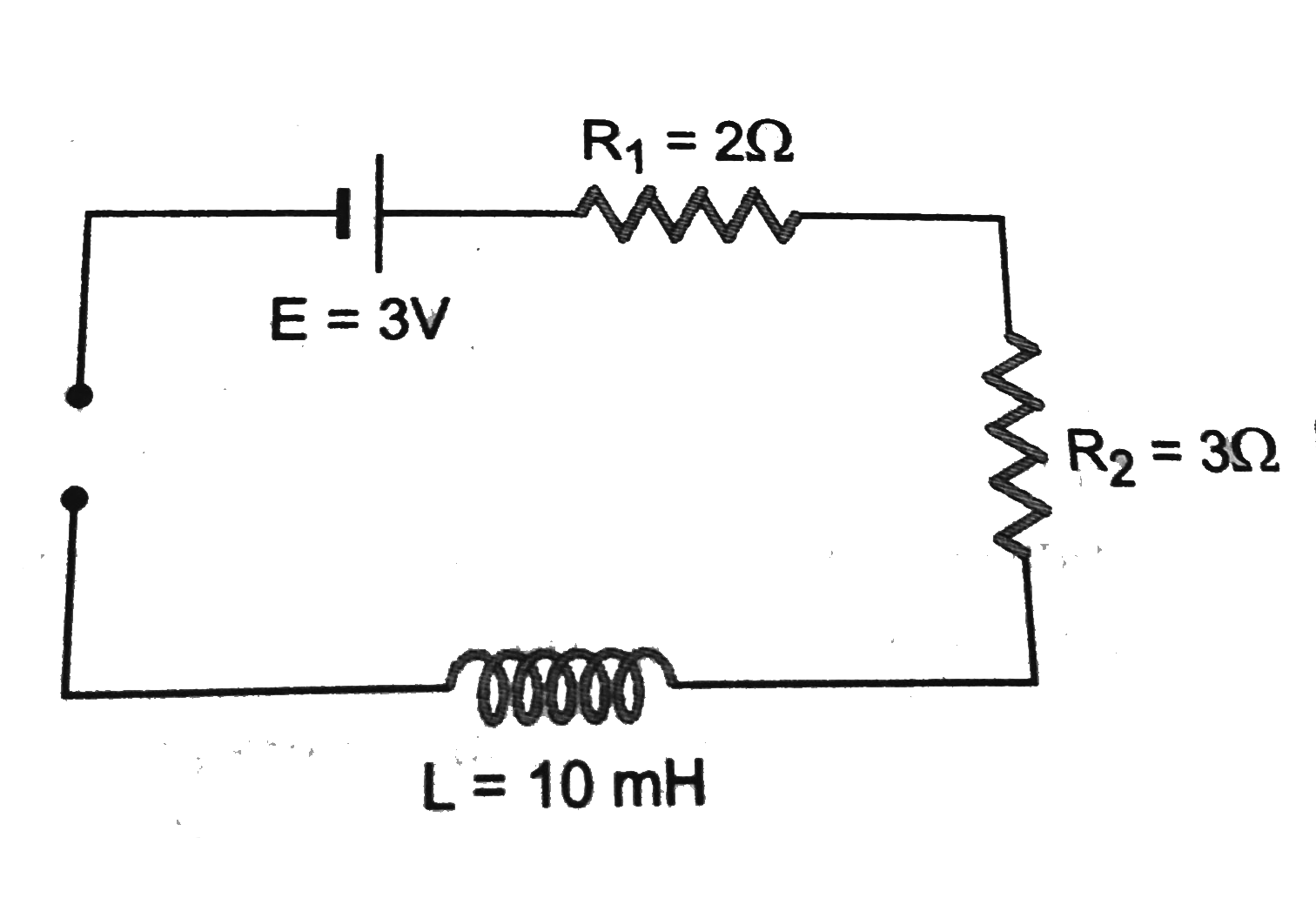
As is known, final steady current in the circuit does not depend on L.
∴I0=ER1+R2=32+3=0.6A
The growth of current in RL circuit is given by Helmholtz equation
I=I0[1−e(−R/L)t]
For I=I0/2, we have to find t
∴I02=I0[1−e(−R/L)t]
12=1−e−Rt/L
e−Rt/L=1−12=12
−RtL=loge1−loge2=0−2.3026×0.3010
=−0.6931
t=0.931×LR=0.931×10×10−32+3
t=1.386×10⁻³s
Now, I=I0/2=0.6/2=0.3A
∴ Energy store in the inductor
U=12LI2=122(10×10−3)(0.3)2
Topper's Solved these Questions
- BOOK - PRADEEPCHAPTER - ELECTROMAGNETIC INDUCTION & ALTERNATING CURRENTEXERCISE - Solved Examples (b)1videos
ELECTROMAGNETIC INDUCTION & ALTERNATING CURRENT
- BOOK - PRADEEPCHAPTER - ELECTROMAGNETIC INDUCTION & ALTERNATING CURRENTEXERCISE - Short Answer Qusetions2videos
ELECTROMAGNETIC INDUCTION & ALTERNATING CURRENT
- BOOK - PRADEEPCHAPTER - DUAL NATURE OF RADIATION AND MATTEREXERCISE - Exercise191videos
DUAL NATURE OF RADIATION AND MATTER
- BOOK - PRADEEPCHAPTER - ELECTROMAGNETIC WAVESEXERCISE - II Focus multiple choice question5videos
ELECTROMAGNETIC WAVES
Similar Questions
A circuit containing a two position switch S is shown in figure
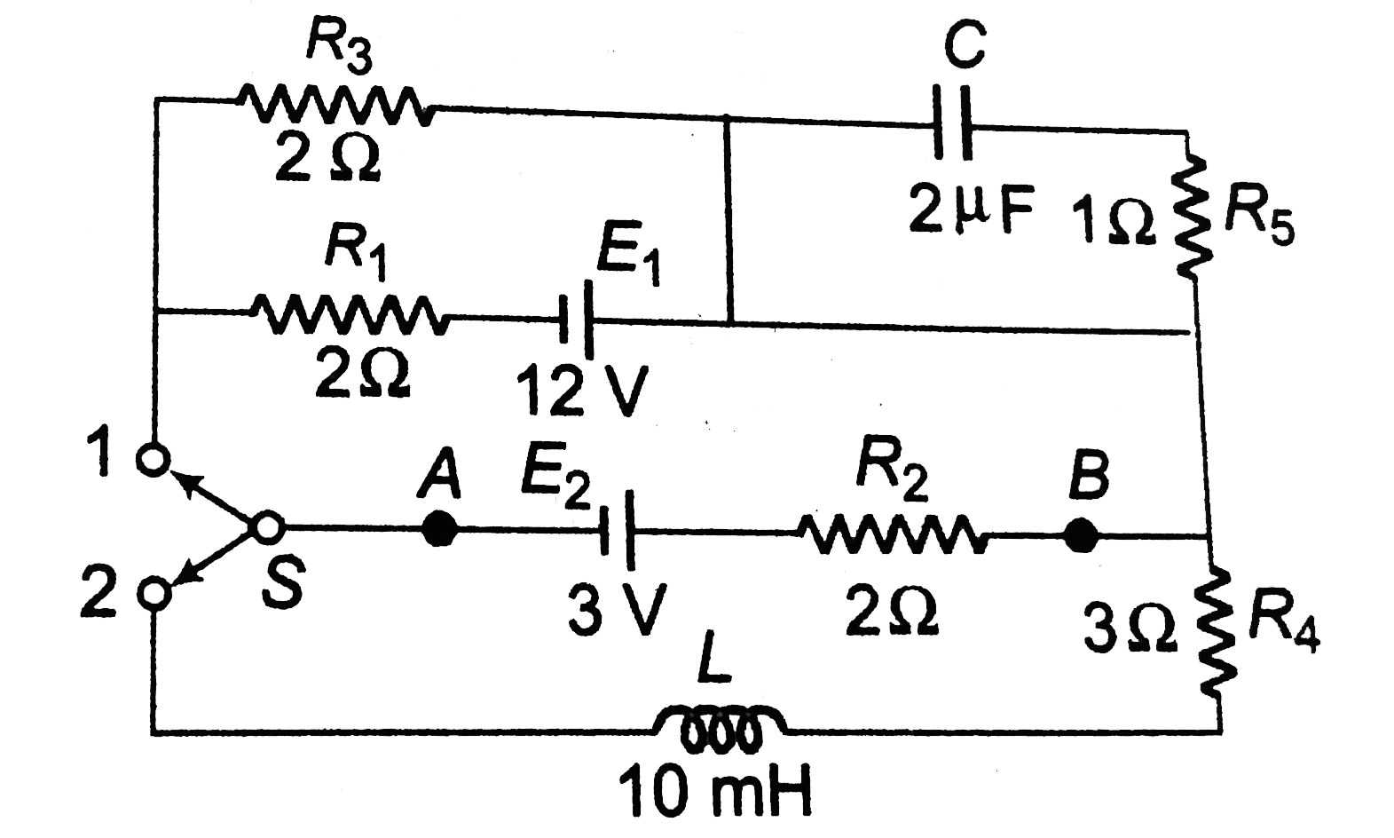
a. The switch S is in position 1. Find the potential differecne VA−VB and the rte of production of joule heat in R1
b. If now the switch S is put in position 2 at t=0. Find ltbRrgt i steady current in R4 and ii hte time when current in R4 is half the steady value. Also calculate the energy stored in the inductor L at that time.View SolutionA circuit containing a two position switch S is shown in fig.
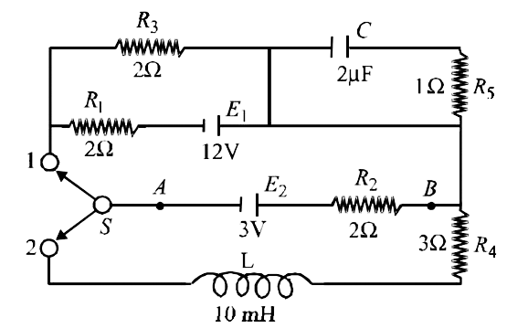
(a) The switch S is in position '1'. Find the potential difference VA−VB and the rate of production of joule heat in (R1).
(b) If now the switch S is put in position 2 at t=0 find
(i) steady current in (R4) and
(ii) the time when current in (R4) is half the steady value.
Also calculate the energy stroed in the inductor L at that time.View Solution
Knowledge Check
- Question 1 - Select One
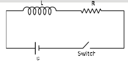
In adjacent circuit, switch S is closed at t = 0. The time at which current in the circuit becomes half of the steady current is
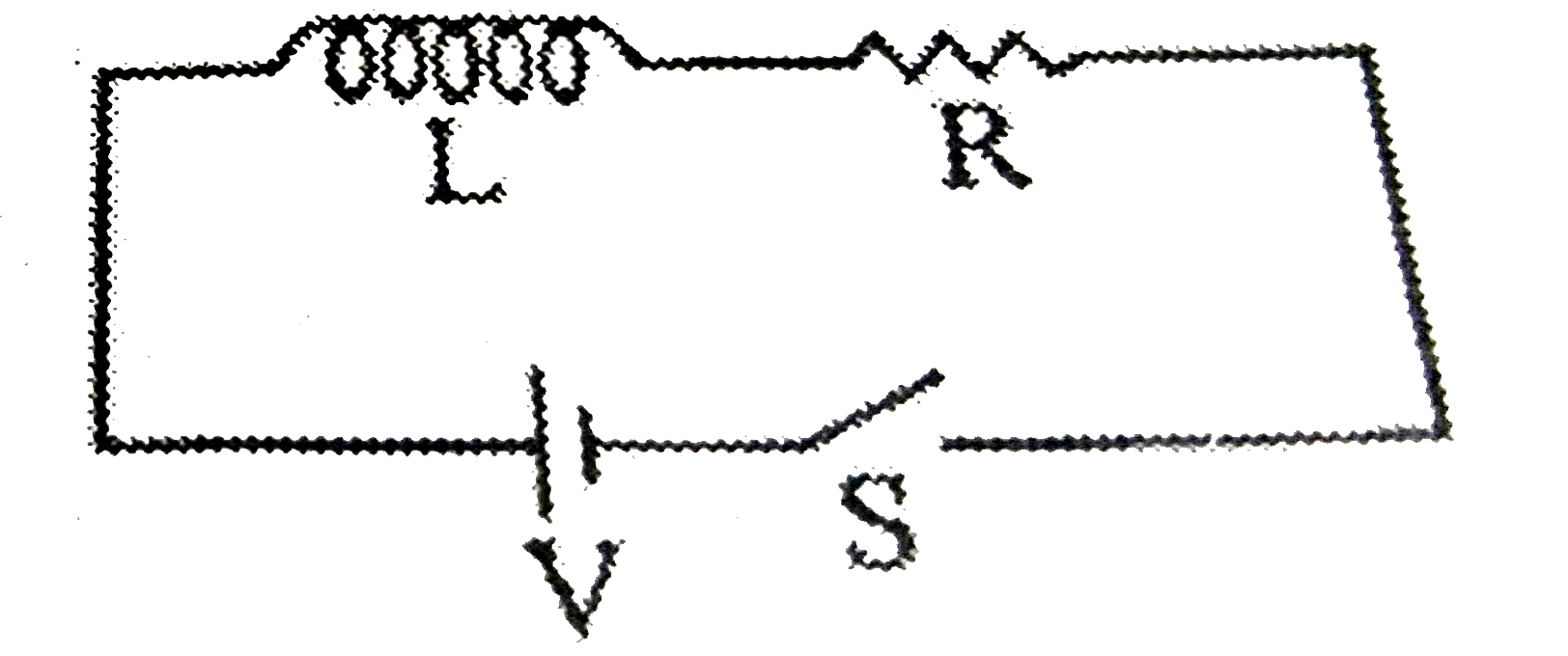 Aτln2Bln2τC2τln2Dτ2ln2
 - Question 2 - Select One
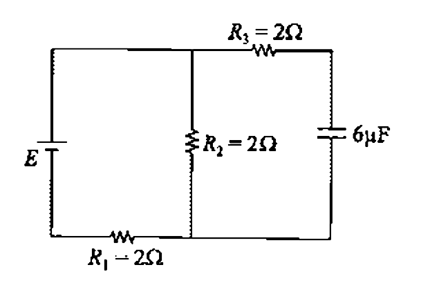
In the circuit shown in figure-3.344 if battery is ideal , then time after which current in R3 becomes (1/e) time that of maximum current through it is :
 A18μsB12μsC6μsD2μs
 - Question 3 - Select One
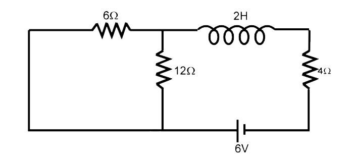
In the circuit shown in fig.. Time constant and steady state current will be
 A0.25s,0.75AB0.75s,0.25AC0.25s,0.25AD0.5s,0.5A
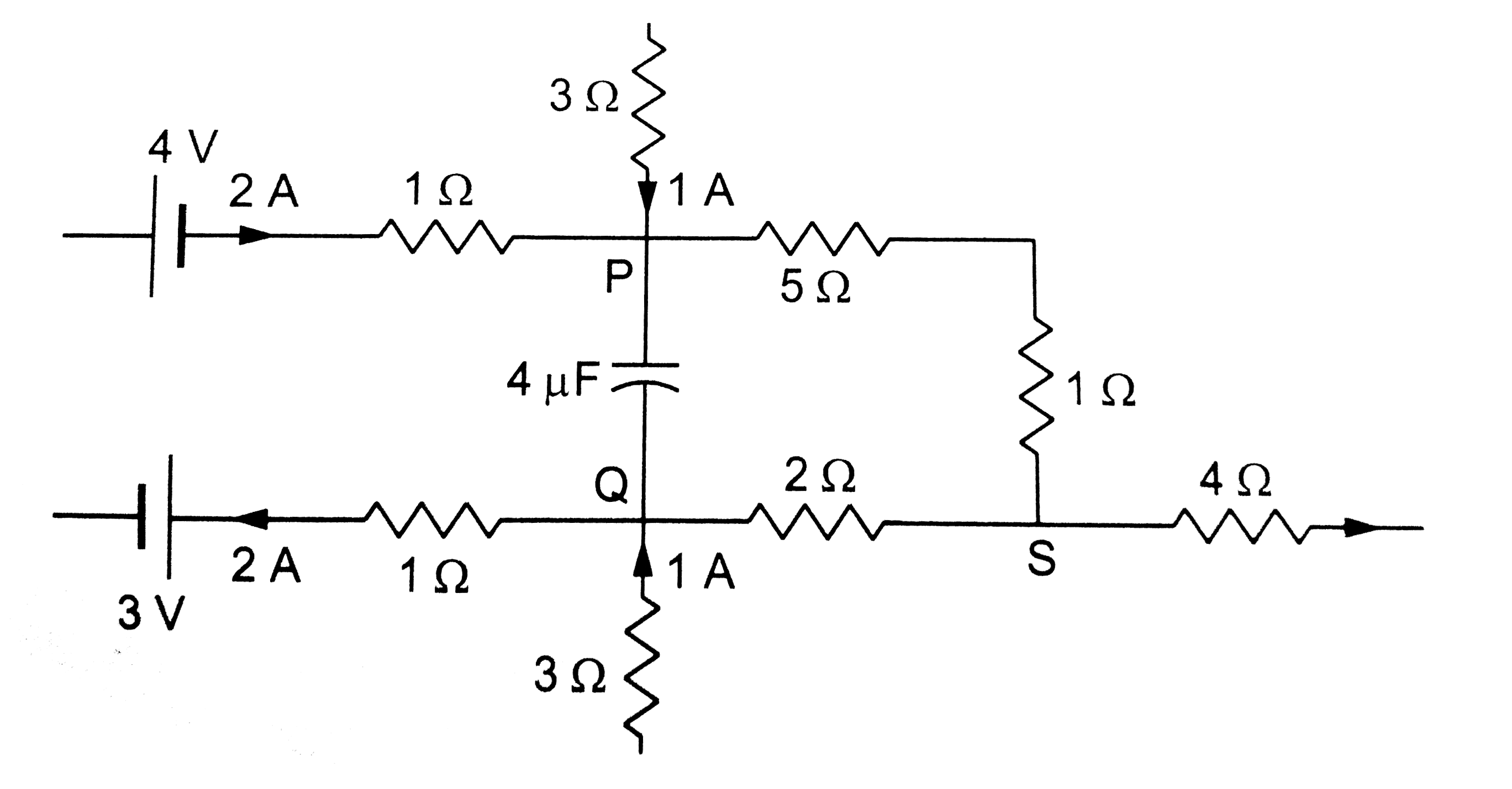
A part of a circuit in steady state along with the currents flowing in the branches,the values of resistances,etc, is shown in figure.Calculate the energy stored in the capacitor.
 View Solution
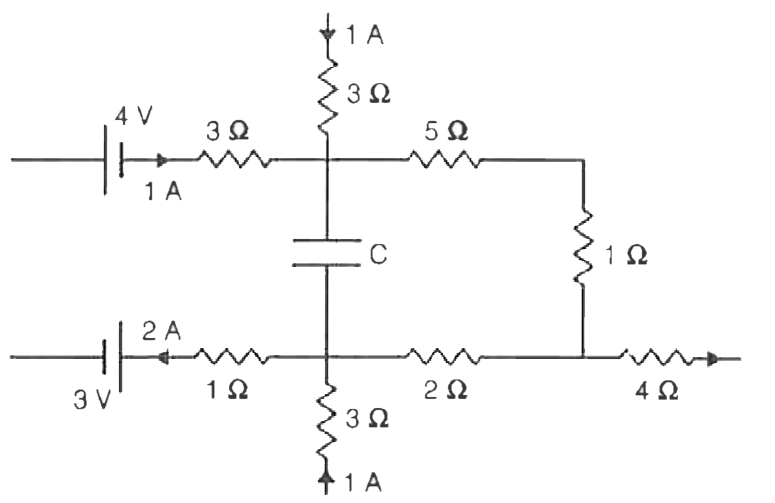
A part of a circuit in the steady state with the currents flowing in the branches and the values of resistance are shown in figure. Calculate the energy stored in the capacitor C=4μF.
 View Solution
A part of the circuit in a steady state along with the currents flowing in the branches, the values of resistance, etc. is shown in the figure. Calculate the energy stored in the capacitor.View SolutionThe circuit is switched on at t=0, Find the time when energy stored in inductor becomes 1n tiimes of maximum energy stored in it:
 View Solution
A part of a circuit in steady state along with the currents flowing in the branches,the values of resistances,etc, is shown in figure.Calculate the energy stored in the capacitor.
 View Solution

