A circuit containing a two position switch S is shown in figure
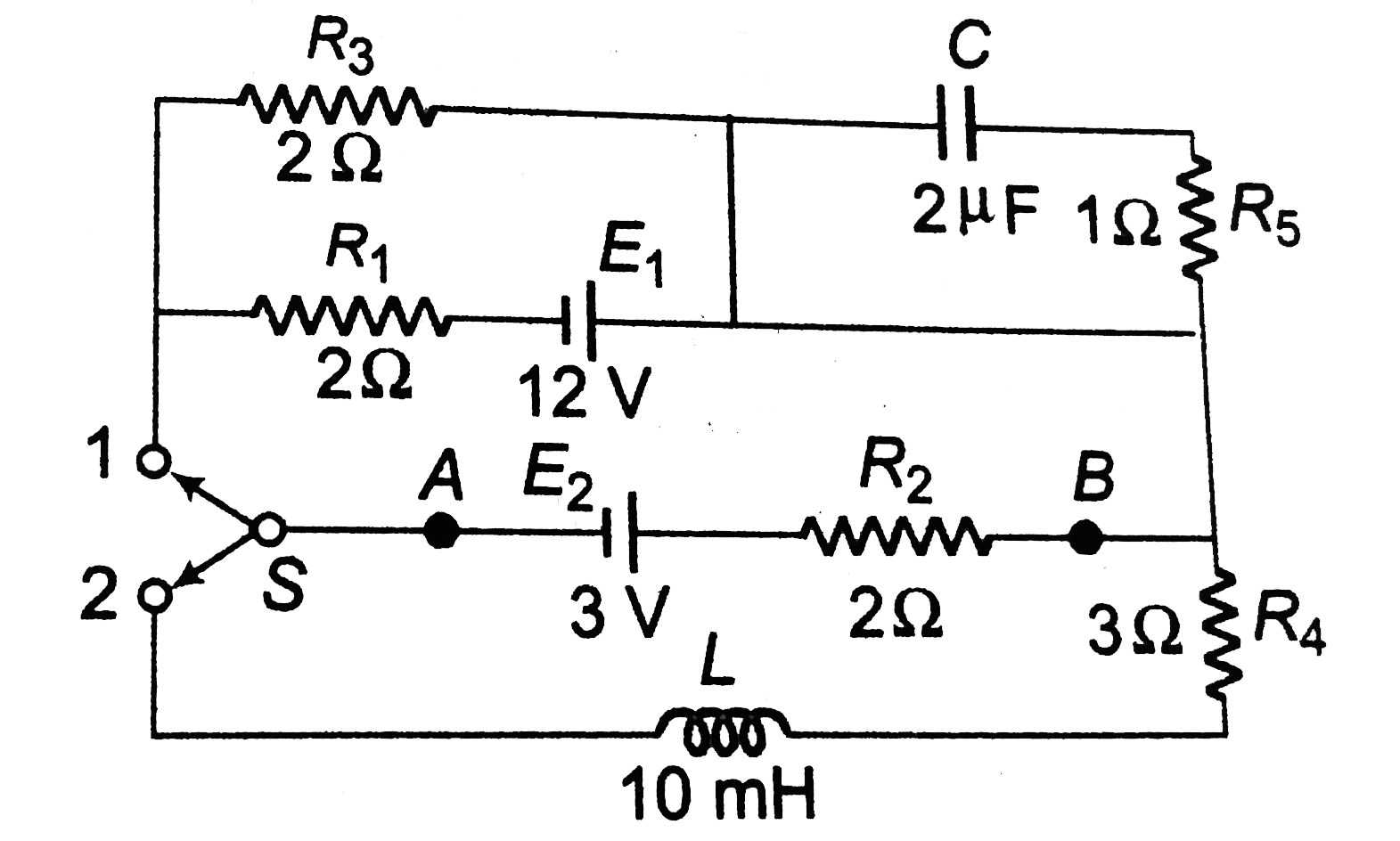
a. The switch S is in position 1. Find the potential differecne VA−VB and the rte of production of joule heat in R1
b. If now the switch S is put in position 2 at t=0. Find ltbRrgt i steady current in R4 and ii hte time when current in R4 is half the steady value. Also calculate the energy stored in the inductor L at that time.
a. In steady state no current will flow through capacitor.

Applying kirchoff's second law in loop 1.
−2i2+2(i1−i2)+12=0
∴2i1−4i2=−12
or i1−2i2=−6……i
Applying Kirchoff's second law in loop 2,
−12−2(i1−i2)+3−2i2=0
∴4i1−2i2=−9 ..(ii)
Solving Eqn i and ii we get
i2=2.5A and i1=−1A
Now VA+3−2i1=VB or VA−VB=2i1−3
=2(−1)−3=−5V
PR1=(i1−i2)2R1=(−1−2.5)2(2)
=24.5W
b. In position 2 Circuit is as below
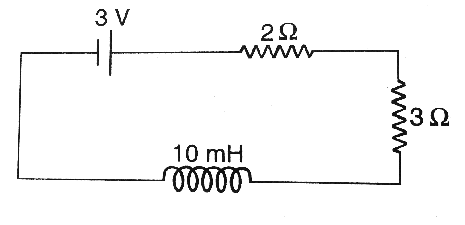
Steady current in R4
i0=33+2=0.6a
Time when current in R4 is half the steady value,
i=i0(1−e−t/τL)
i=i02att=t12, where
t1/2=τL(In2)=LRIn(2)=(10×10−3)5In(2)
=1.386x1210x10−3s
U=12Li2=12(10×10−3)(0.3)2
=4.5×10⁻⁴J
Topper's Solved these Questions
- BOOK - DC PANDEYCHAPTER - ELECTROMAGNETIC INDUCTIONEXERCISE - Example Type 42videos
ELECTROMAGNETIC INDUCTION
- BOOK - DC PANDEYCHAPTER - ELECTROMAGNETIC INDUCTIONEXERCISE - Example Type 52videos
ELECTROMAGNETIC INDUCTION
- BOOK - DC PANDEYCHAPTER - ELECTROMAGNETIC INDUCTIONEXERCISE - Example Type 22videos
ELECTROMAGNETIC INDUCTION
- BOOK - DC PANDEYCHAPTER - CURRENT ELECTRICITYEXERCISE - Medical entrances gallery97videos
CURRENT ELECTRICITY
- BOOK - DC PANDEYCHAPTER - ELECTROMAGNETIC WAVESEXERCISE - Sec C22videos
ELECTROMAGNETIC WAVES
Similar Questions
A circuit containing a two position switch S is shown in fig.
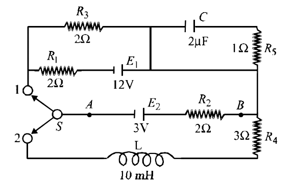
(a) The switch S is in position '1'. Find the potential difference VA−VB and the rate of production of joule heat in (R1).
(b) If now the switch S is put in position 2 at t=0 find
(i) steady current in (R4) and
(ii) the time when current in (R4) is half the steady value.
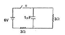
Also calculate the energy stroed in the inductor L at that time.View SolutionThe switch S of the circuit is closed at t = 0. Find the current (in Amp.) through the capacitor when the switch S is closed at t = 0
 View Solution
Knowledge Check
- Question 1 - Select One
In the circuit shown in figure, switch S is initially closed and S is open. Find V-V
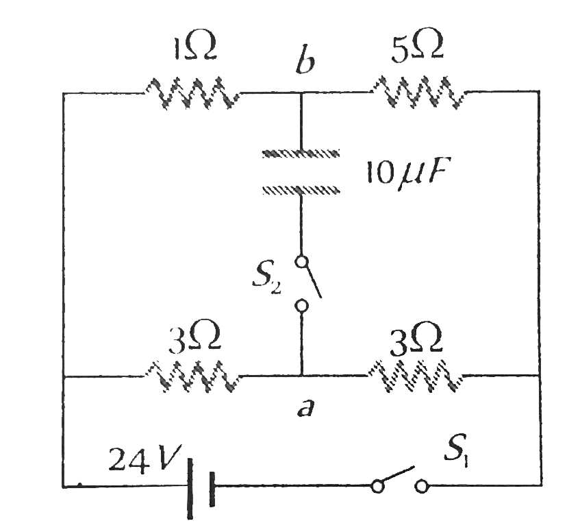 A4VB8VC12VD16V
 - Question 2 - Select One
In the circuit given in fig. swithc S is at position 1 for long time. Find the total heat generated in resistor of resistance (2r0), when the switch S is shifted from position 1 to position 2.
 AC0E202BC0E20CC0E203Dnone
 - Question 3 - Select One
In the circuit shown in figure switch S is thrown to position 1 at t=0. when the current in the resistor is 1A, it is shifted to position 2. the total heat generated in the circuit after shifting to position 2 is
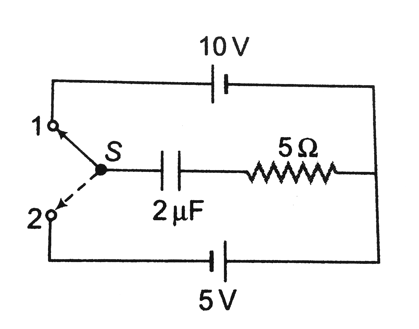 AzeroB625μJC100μJDnone of these
Find heat produced in the circuit shown in figure on closing the switch S.
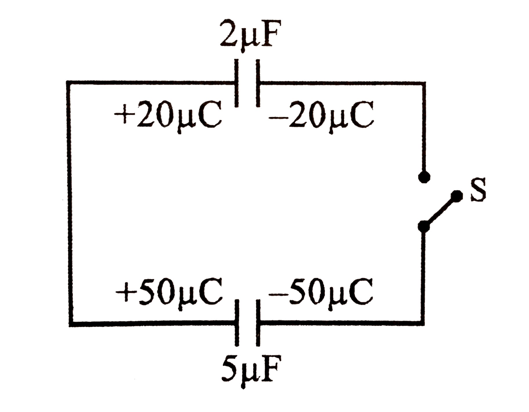 View Solution
In the circuit shown in figure L=10H,R=5Ω,E=15V. The switch S is closed at t=0. At t=2s the current in the circuit is
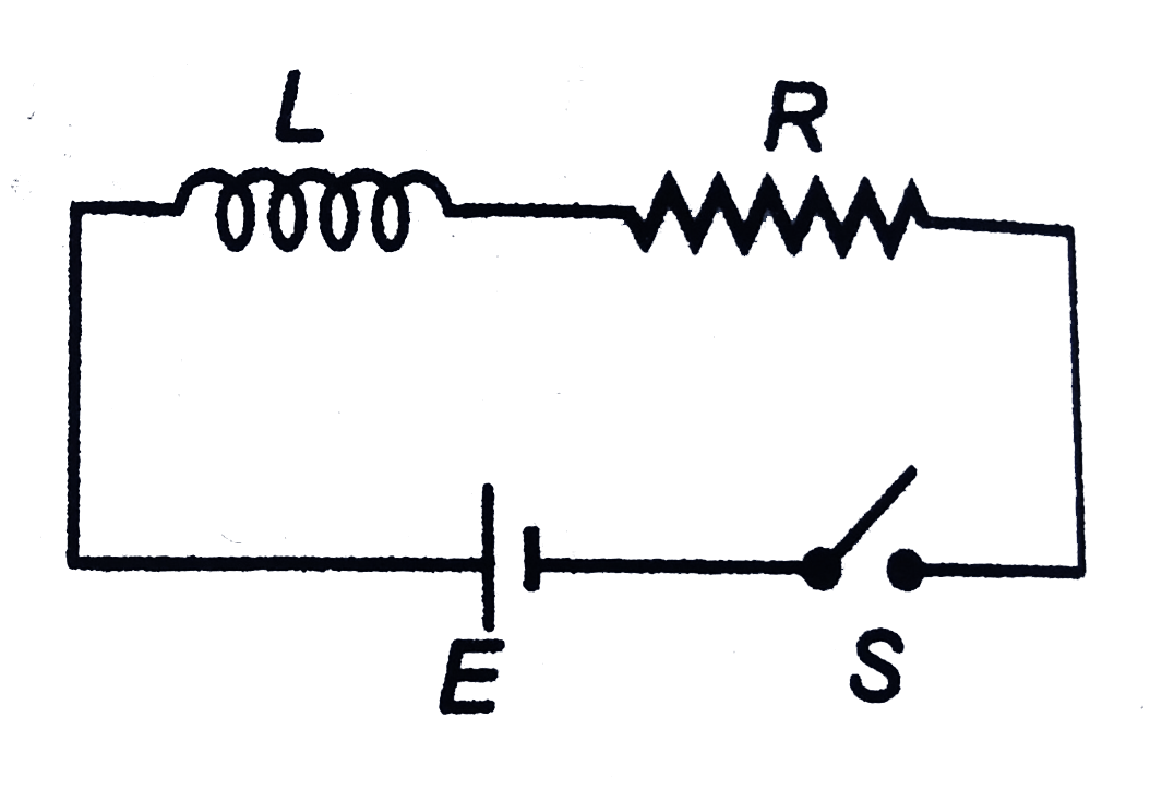 View Solution
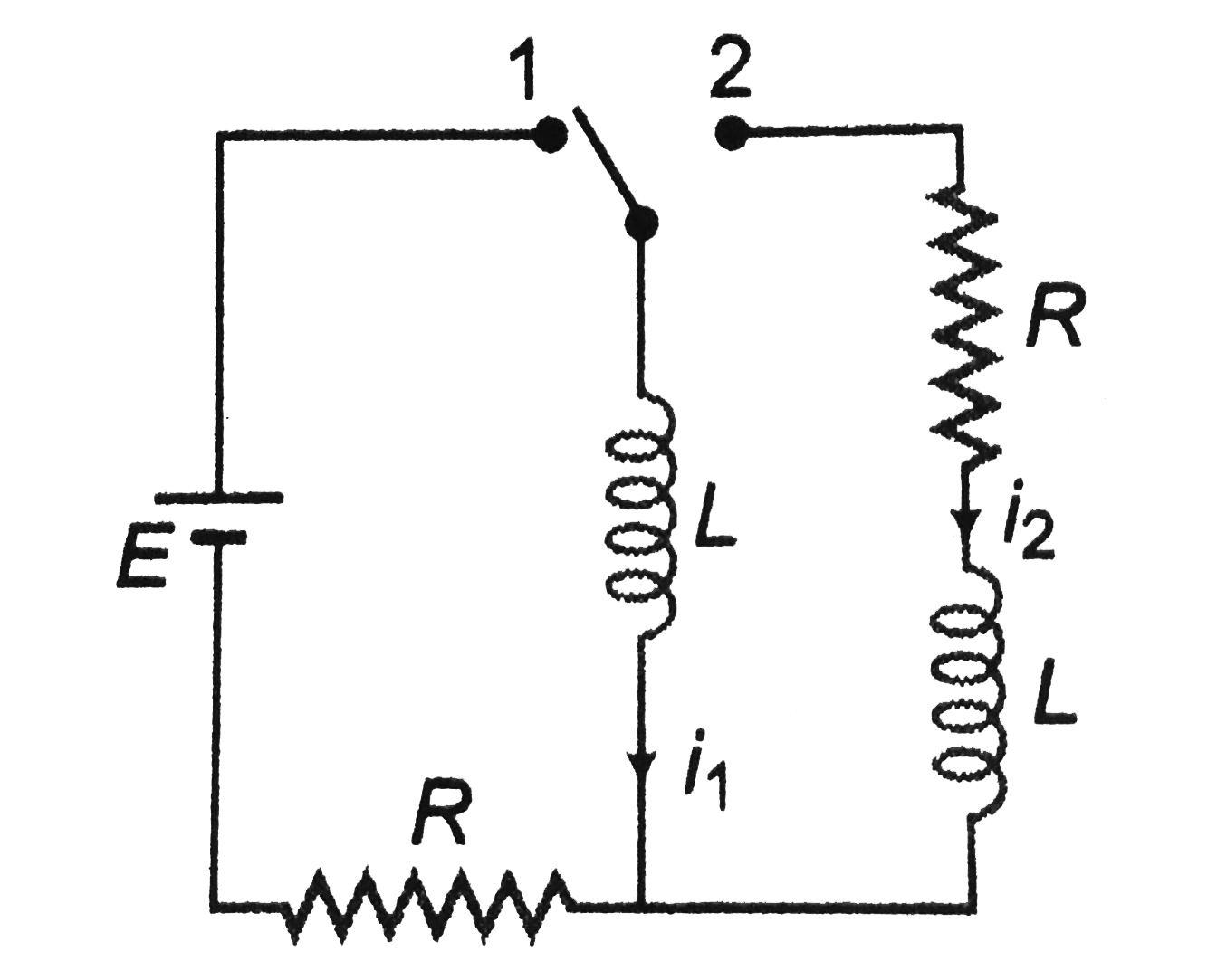
In figure, the switch is in the position 1 for long time, then the switch is shifted to position 2 at t=0. At this instant the value of i1 and i2 are
 View Solution
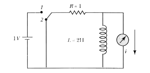
In the circuit shown in the following figure, the switch is moved to position 1 at t = 0. Which of the following most closely represents the current I as a function of time?
 View Solution
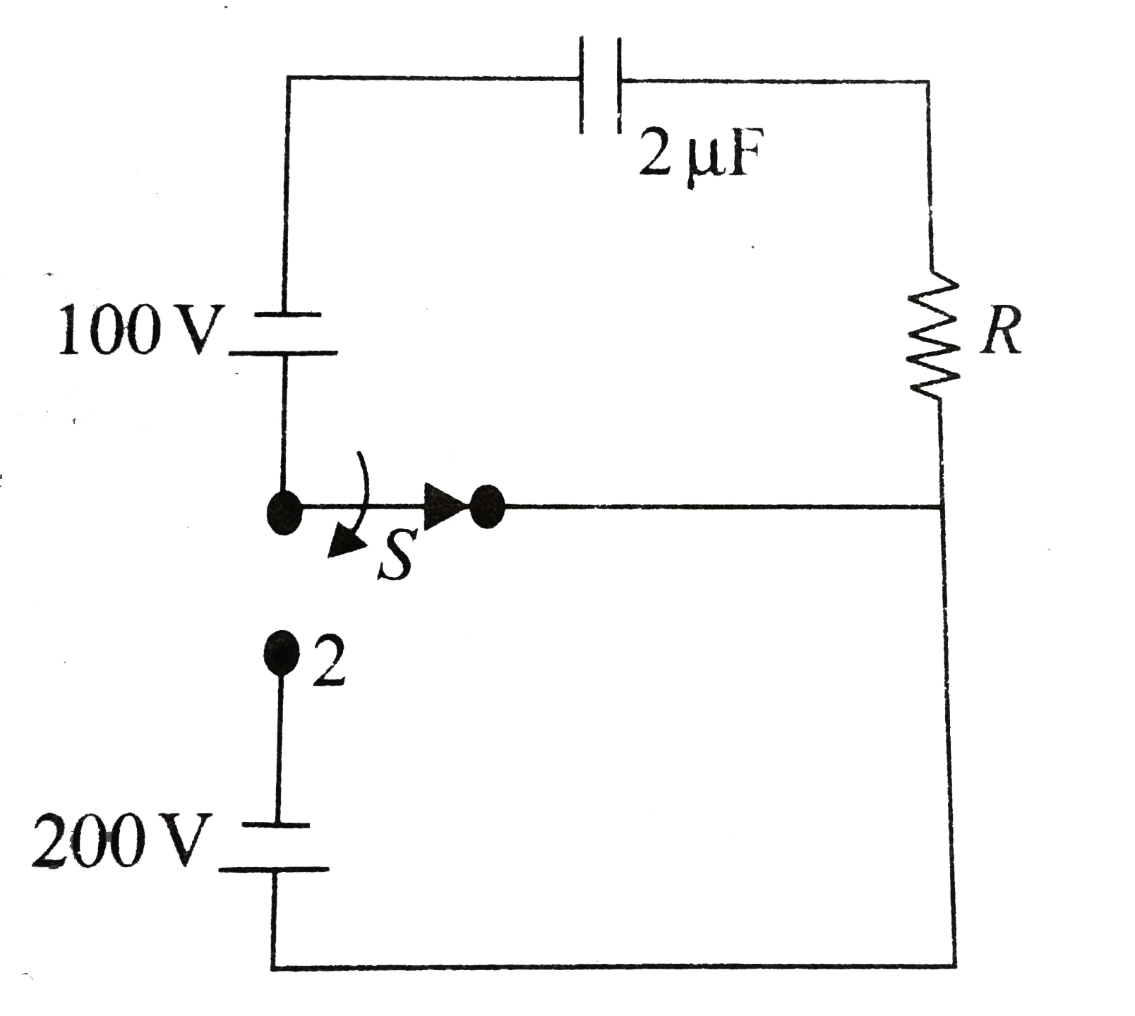
In the circuit shown in the figure, the switch S is in position 1 for a long time. Now the switch is thrown to position 2. Find the total heat developed in the circuit till the steady state is reached again.
 View Solution

