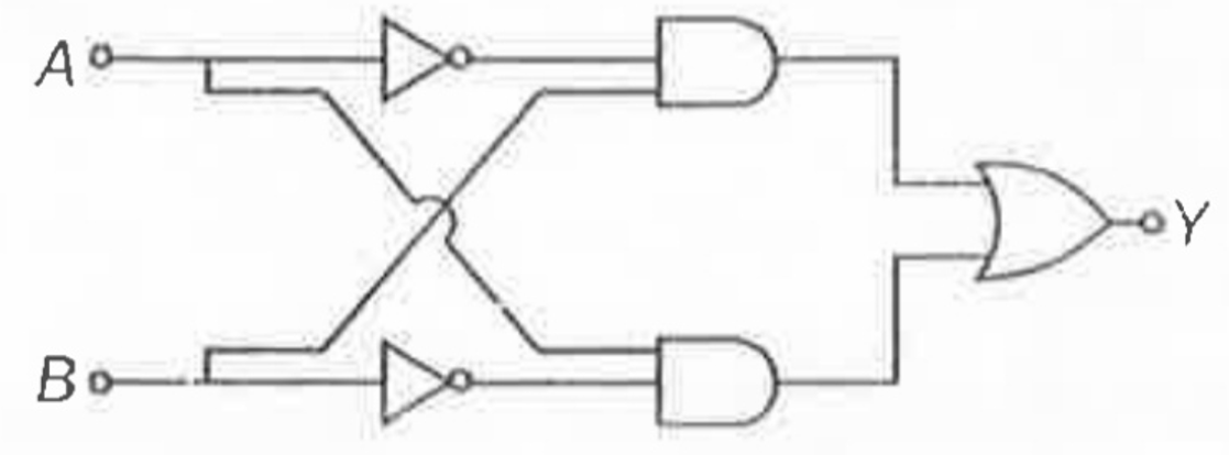
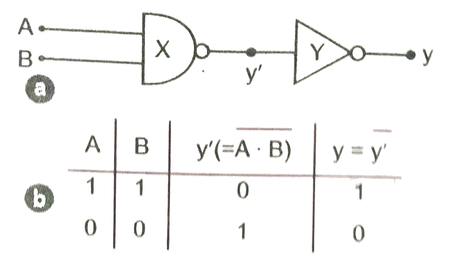
The logic circuit Fig. represents

NAND gate with outlet, O=¯¯¯X+¯¯¯Y
NOR gate with outlet, O=¯¯¯¯¯¯¯¯¯¯¯X+Y
NAND gate with outlat, O=¯¯¯¯¯¯¯¯X.Y
NOR gate with outlet, O=¯¯¯X.¯¯¯Y
The correct Answer is:B
Step by step video, text & image solution for The logic circuit Fig. represents by Physics experts to help you in doubts & scoring excellent marks in Class 12 exams.
Updated on:21/07/2023Topper's Solved these Questions
- ELECTRONIC DEVICESBOOK - PRADEEPCHAPTER - ELECTRONIC DEVICESEXERCISE - LONG QUESTION ANSWER
2 Videos
- ELECTRONIC DEVICESBOOK - PRADEEPCHAPTER - ELECTRONIC DEVICESEXERCISE - PROBLEMS FOR PRACTICE
7 Videos
- ELECTRONIC DEVICESBOOK - PRADEEPCHAPTER - ELECTRONIC DEVICESEXERCISE - HIGHER ORDER THINKING SKILLS
1 Videos
- ELECTROMAGNETIC WAVESBOOK - PRADEEPCHAPTER - ELECTROMAGNETIC WAVESEXERCISE - II Focus multiple choice question
5 Videos
- ELECTROSTATICSBOOK - PRADEEPCHAPTER - ELECTROSTATICSEXERCISE - ASSERTION-REASON TYPE QUESTIONS
2 Videos
Similar Questions
Knowledge Check
The Boolean expression P+¯¯¯PQ, where P and Q are the inputs of the logic circuit, represents
AAND gateBNAND gateCNOT gateDOR gateThe circuit given below represents which of the logic operations ?
 AANDBNOTCORDNOR
The circuit given below represents which of the logic operations ?
 AANDBNOTCORDNOR
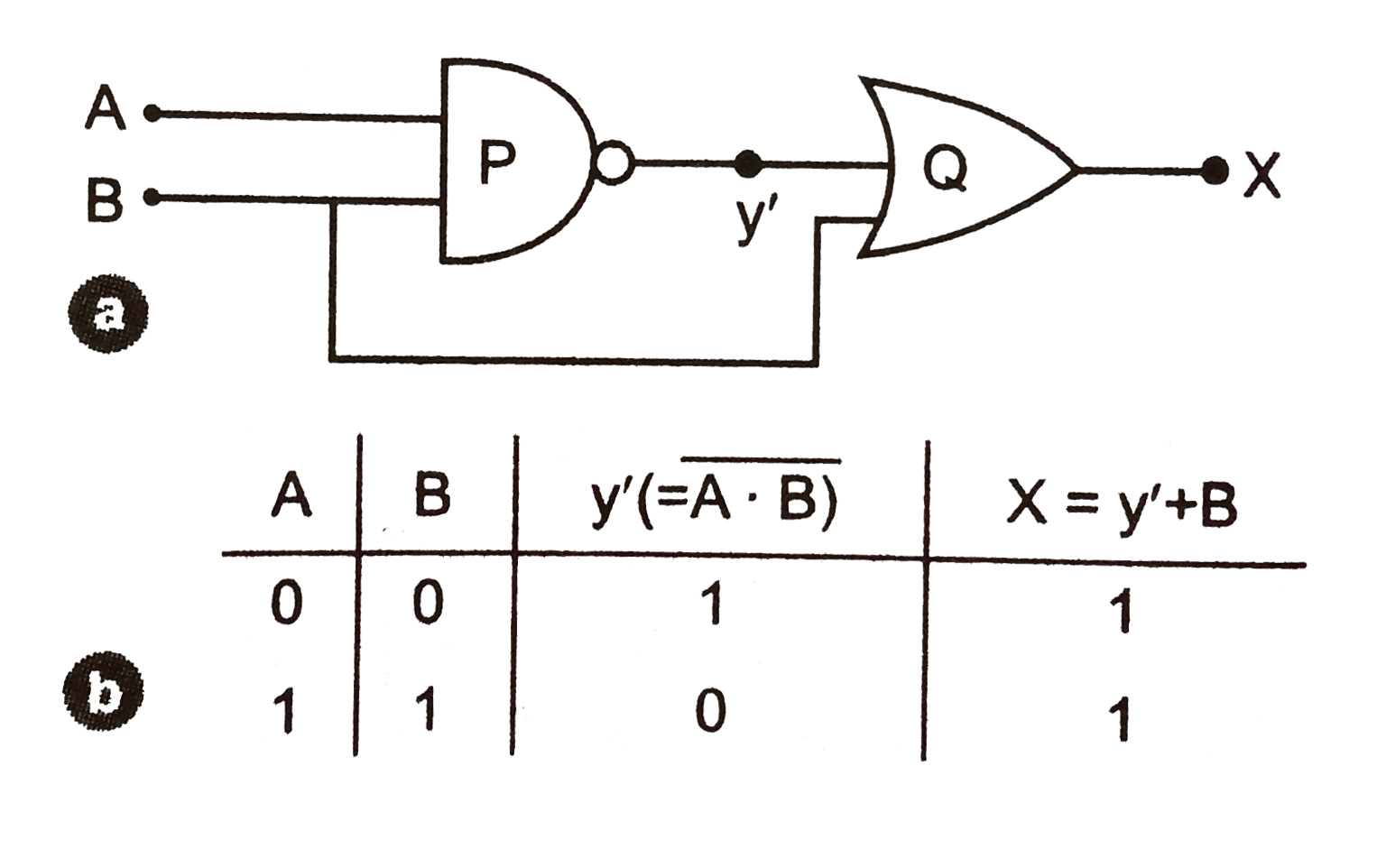
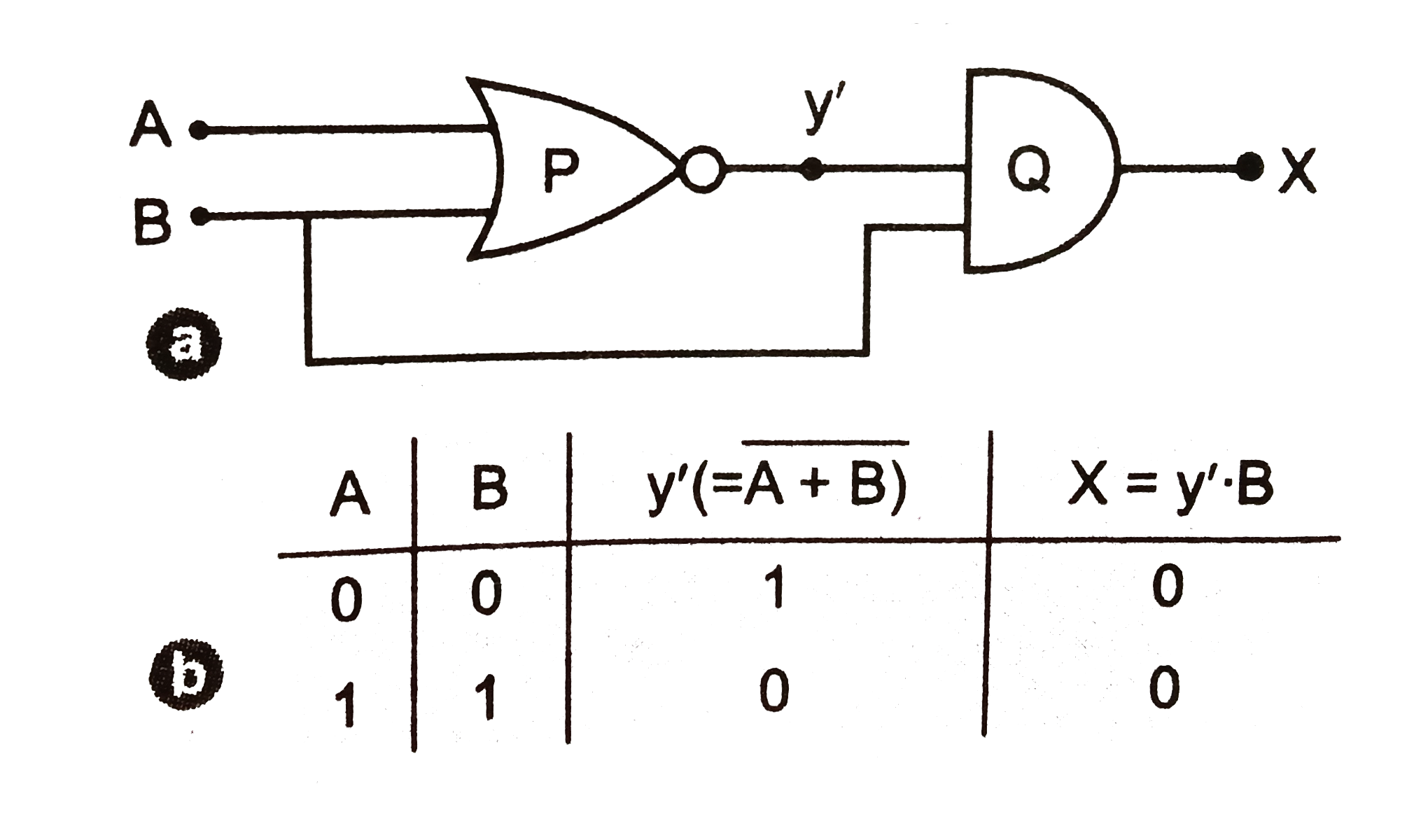
Identify the logic gates marked P and Q in the given logic circuit Fig. Write down then output at X for the inputs
(i) A=0,B=0 and (ii) A=1,B=1.

View SolutionIdentify the logic gate markeed P and Q in the given logic circuit Fig . Write down the output at X for the inputs
(i) A=0,B=0 and (ii) A=1,B=1.

View Solution(i) Identify the logic gates marked P and Q in the given logic circuit Fig.

(ii) Write down the output at X for the inputs A=0,B=0 and A=1,B=1.
View SolutionThe ouptu x of the logic circuit will be

View SolutionThe circuit given below represents which of the logic operations?

View Solution


