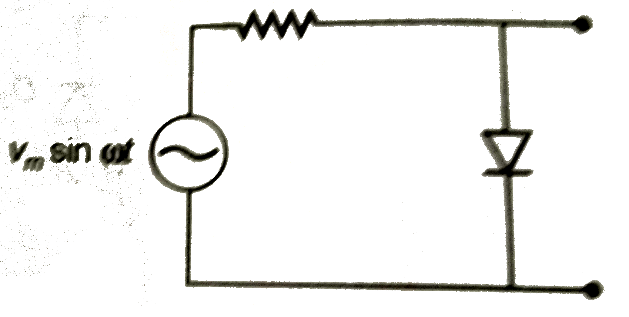
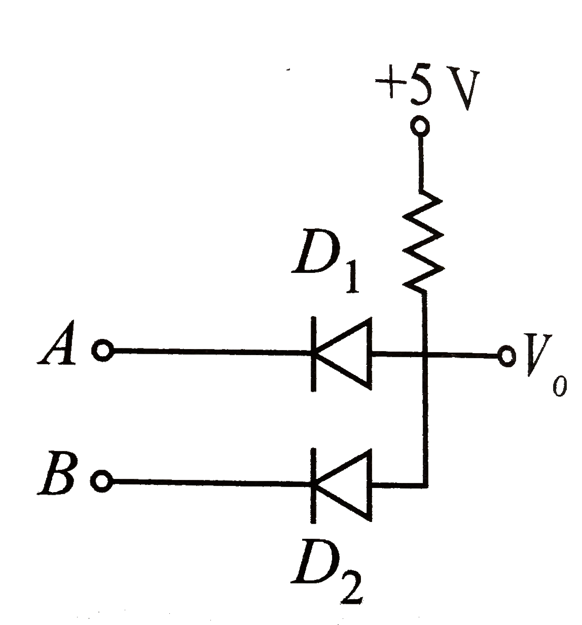
The output of the given circuit in figure given below,
A
would be zero at all times.
B
would be like a half wave rectifier with positive cycles in output
C
would be like a half wave rectifier with negative cycles in output.
D
would be like that of a full wave rectifier.
Video Solution
Text Solution
The correct Answer is:C
During positive half cycle of input ac voltage, the p-n junction is forward biased. The resistance of p-n junction is low. The current in the circuit is maximum In this situation, a maximum potential difference will appear across resistance connected in series of circuit.Due to it, there is no output voltage across p-n junction. During the negative half cycle of input ac voltage, the p-n junction is reverse biased. The resistance of p-n junction becomes high which will be more than resistance in series. Due to it, there will be voltage across p-n junction with negative cycle in output.Thus, option (c) is correct.
|
Topper's Solved these Questions
- SEMICONDUCTOR ELECTRONICS : MATERIALS , DEVICES AND SIMPLE CIRCUITS BOOK - NCERT FINGERTPS ENGLISHCHAPTER - SEMICONDUCTOR ELECTRONICS : MATERIALS , DEVICES AND SIMPLE CIRCUITS EXERCISE - ASSERTION & REASON
15 Videos
- SEMICONDUCTOR ELECTRONICS : MATERIALS , DEVICES AND SIMPLE CIRCUITS BOOK - NCERT FINGERTPS ENGLISHCHAPTER - SEMICONDUCTOR ELECTRONICS : MATERIALS , DEVICES AND SIMPLE CIRCUITS EXERCISE - Classification Of Metals, Conductors And Semiconductors
8 Videos
- SEMICONDUCTOR ELECTRONICS : MATERIALS , DEVICES AND SIMPLE CIRCUITS BOOK - NCERT FINGERTPS ENGLISHCHAPTER - SEMICONDUCTOR ELECTRONICS : MATERIALS , DEVICES AND SIMPLE CIRCUITS EXERCISE - HOTS
8 Videos
- RAY OPTICS AND OPTICAL INSTRUMENTSBOOK - NCERT FINGERTPS ENGLISHCHAPTER - RAY OPTICS AND OPTICAL INSTRUMENTSEXERCISE - NCERT Exemplar
11 Videos
- WAVE OPTICSBOOK - NCERT FINGERTPS ENGLISHCHAPTER - WAVE OPTICSEXERCISE - Assertion And Reason
15 Videos
Similar Questions
Knowledge Check
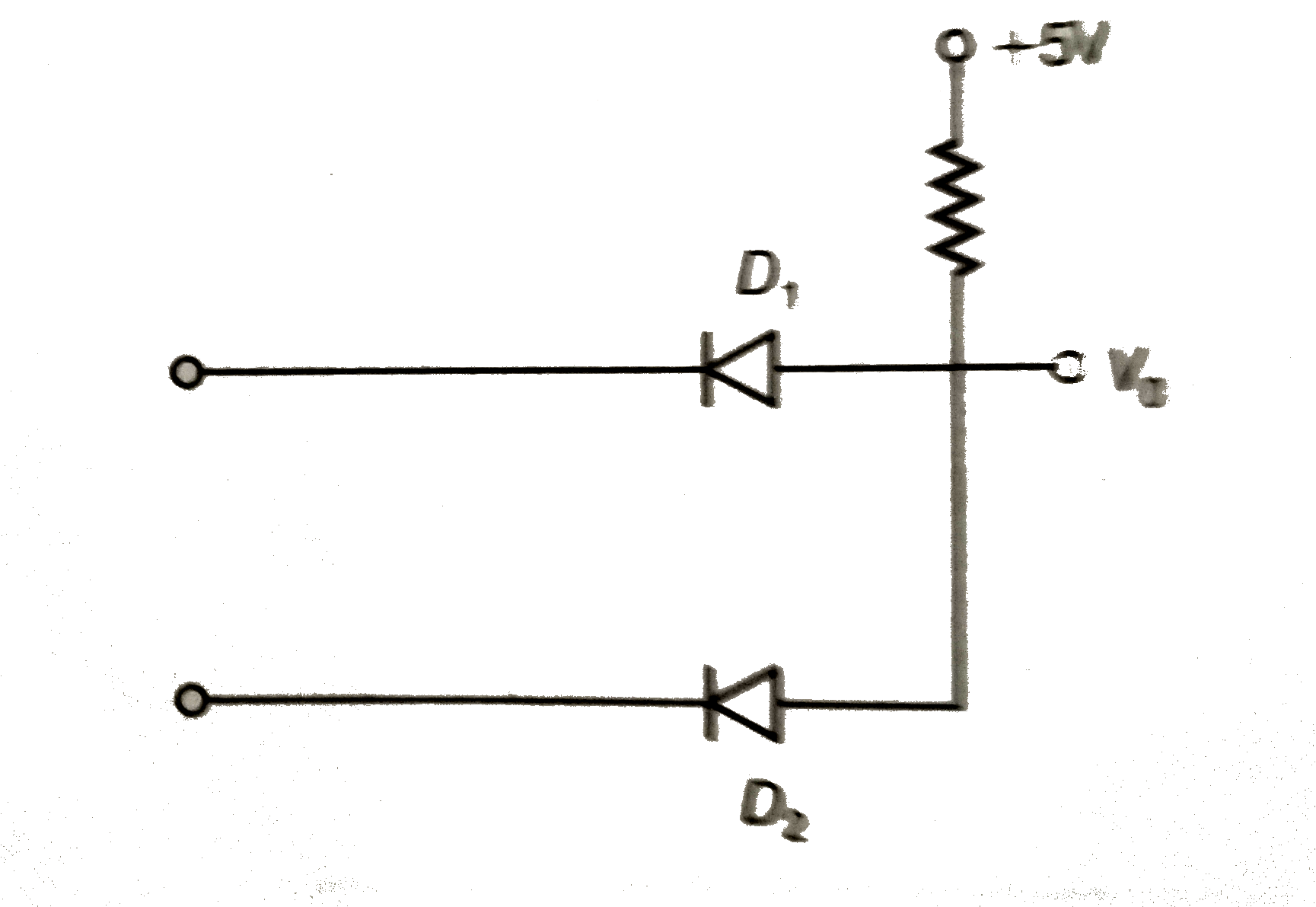
Write the truth table for the circuit shown in figure given below. Name the gate that the circuit resembles.
 ANANDBANDCORDNOR
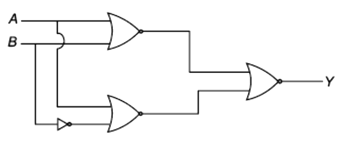
The output of the given logic gate is

View SolutionThe output of the given logica gate is

View Solutionthe output given logic circuit is :
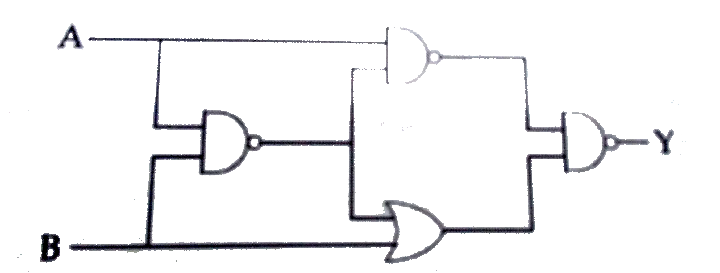
View SolutionThe output (X) of the logic circuit shown in figure will be

View SolutionStudy the circuits shown in the figure. Name the gate that the given circuit resembles.
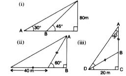
View SolutionIn the figures given below , find AB:
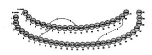
View SolutionIdentify the figure given below.
View Solution


