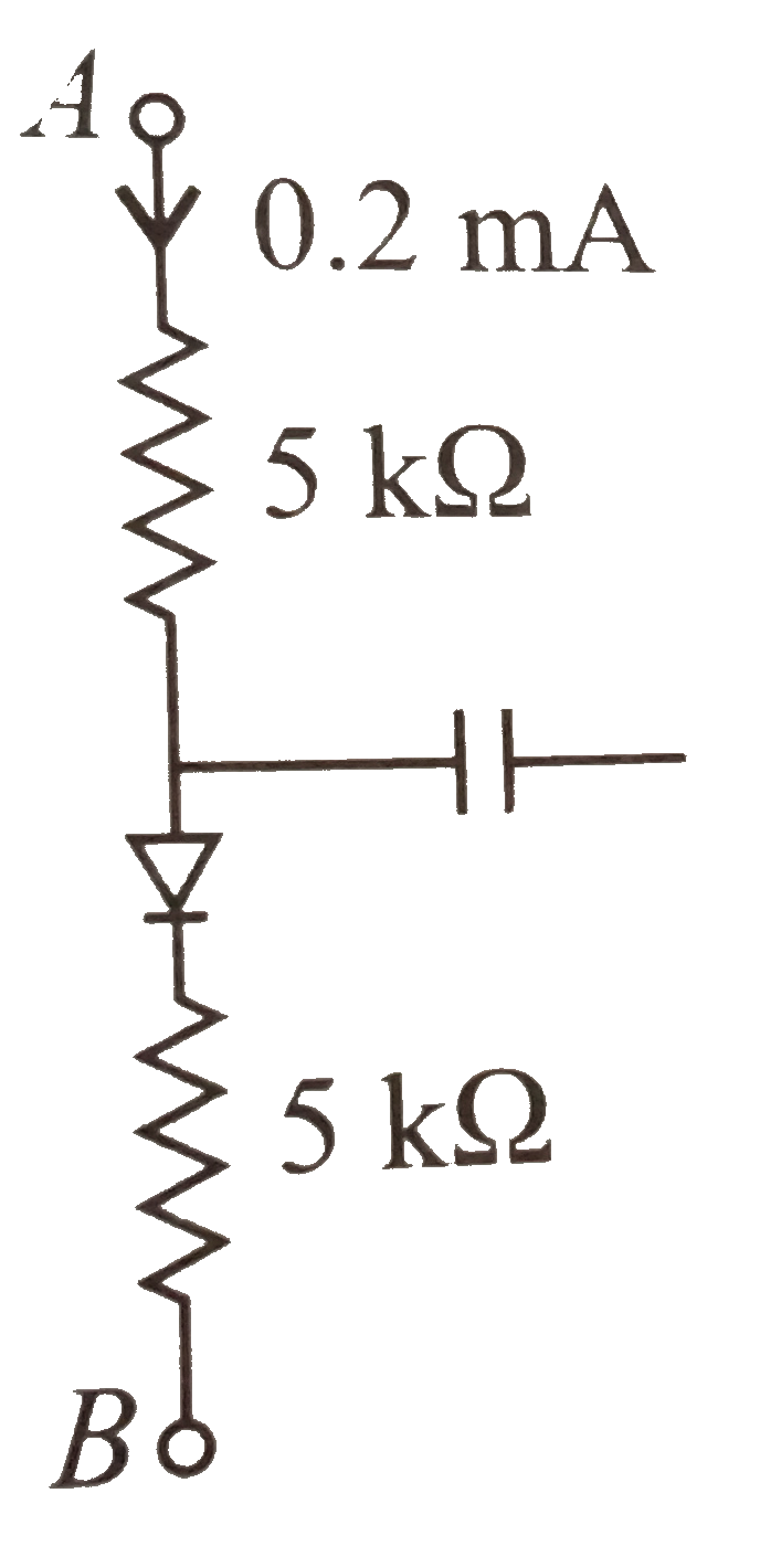
In the circuit shown in figure, if the A diode forward voltage drop is 0.3 V, the voltage difference between A and B is
1.3 V
2.3 V
0
0.5 V
The correct Answer is:B
Let V be the potential difference between A and B, then
V−0.3=(5+5)×103×(0.2×10−3)=2
or V=2+0.3=2.3V
Topper's Solved these Questions
- SEMICONDUCTOR ELECTRONICS : MATERIALS , DEVICES AND SIMPLE CIRCUITS BOOK - NCERT FINGERTPS ENGLISHCHAPTER - SEMICONDUCTOR ELECTRONICS : MATERIALS , DEVICES AND SIMPLE CIRCUITS EXERCISE - ASSERTION & REASON
15 Videos
- SEMICONDUCTOR ELECTRONICS : MATERIALS , DEVICES AND SIMPLE CIRCUITS BOOK - NCERT FINGERTPS ENGLISHCHAPTER - SEMICONDUCTOR ELECTRONICS : MATERIALS , DEVICES AND SIMPLE CIRCUITS EXERCISE - Classification Of Metals, Conductors And Semiconductors
8 Videos
- SEMICONDUCTOR ELECTRONICS : MATERIALS , DEVICES AND SIMPLE CIRCUITS BOOK - NCERT FINGERTPS ENGLISHCHAPTER - SEMICONDUCTOR ELECTRONICS : MATERIALS , DEVICES AND SIMPLE CIRCUITS EXERCISE - HOTS
8 Videos
- RAY OPTICS AND OPTICAL INSTRUMENTSBOOK - NCERT FINGERTPS ENGLISHCHAPTER - RAY OPTICS AND OPTICAL INSTRUMENTSEXERCISE - NCERT Exemplar
11 Videos
- WAVE OPTICSBOOK - NCERT FINGERTPS ENGLISHCHAPTER - WAVE OPTICSEXERCISE - Assertion And Reason
15 Videos
Similar Questions
Knowledge Check
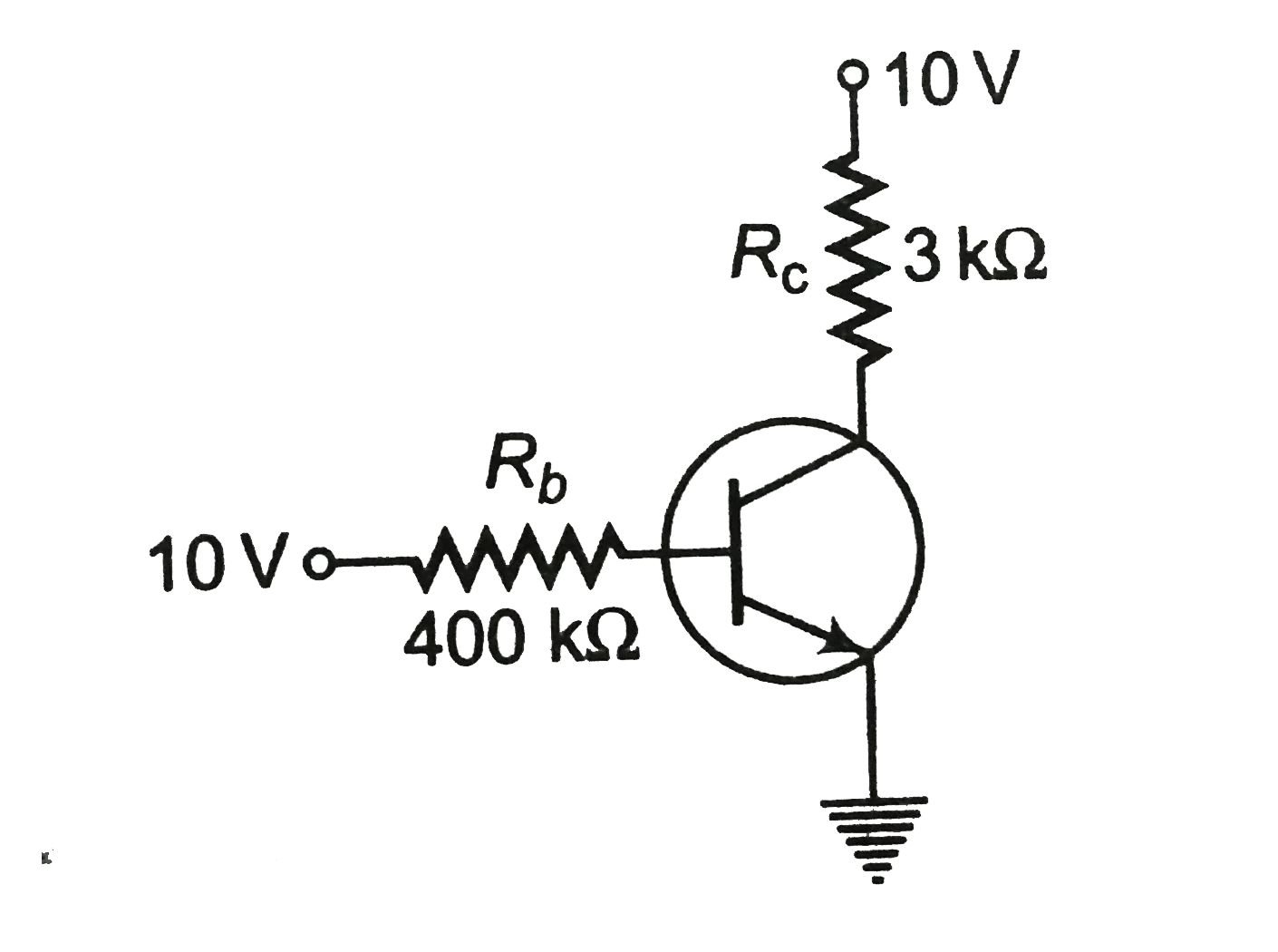
In the circuit shown in figure, when the input voltage of the base resistance is 10 V, Vbe is zero and Vce is also zero. Then
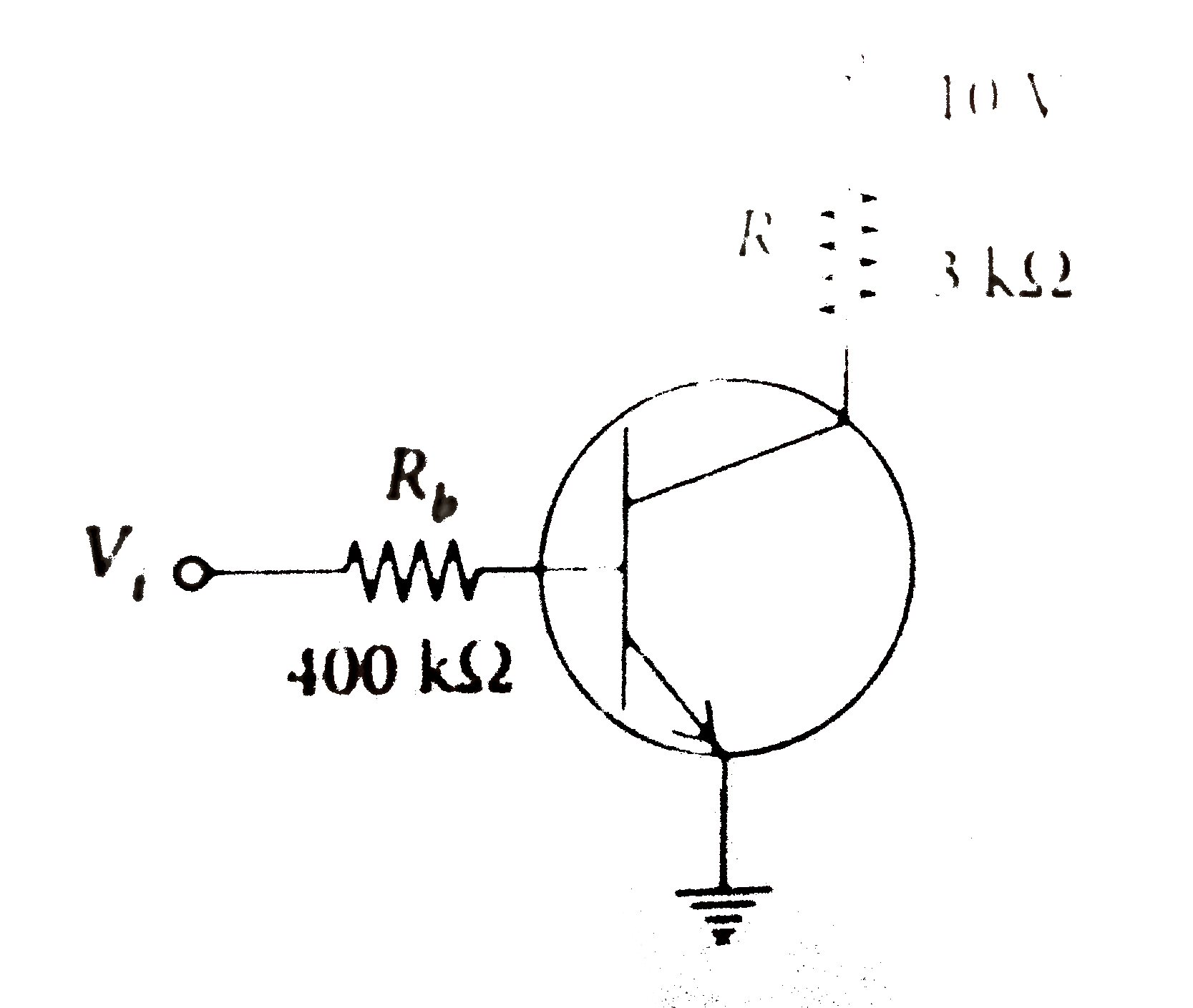 Aβ=110BIb=25μACIc=3.33mADboth (A) and (C )
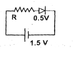
The diode used in the circuit shown in the figure has a constant voltage drop of 0.5V at all currents and a maximum power rating fo 100 milliwatts. What should be the value of the resistor R, connected in series with the diode for obtaining maximum current?
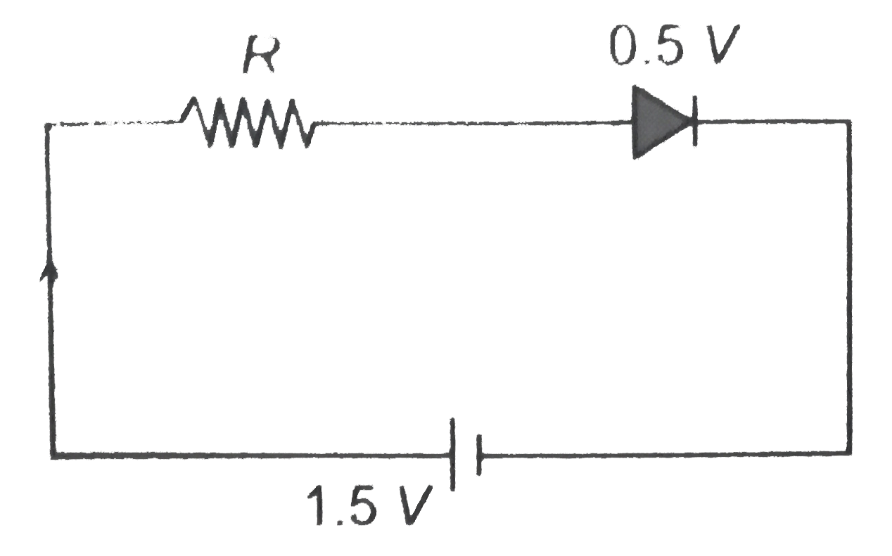 A6.76ΩB20ΩC5ΩD5.6Ω
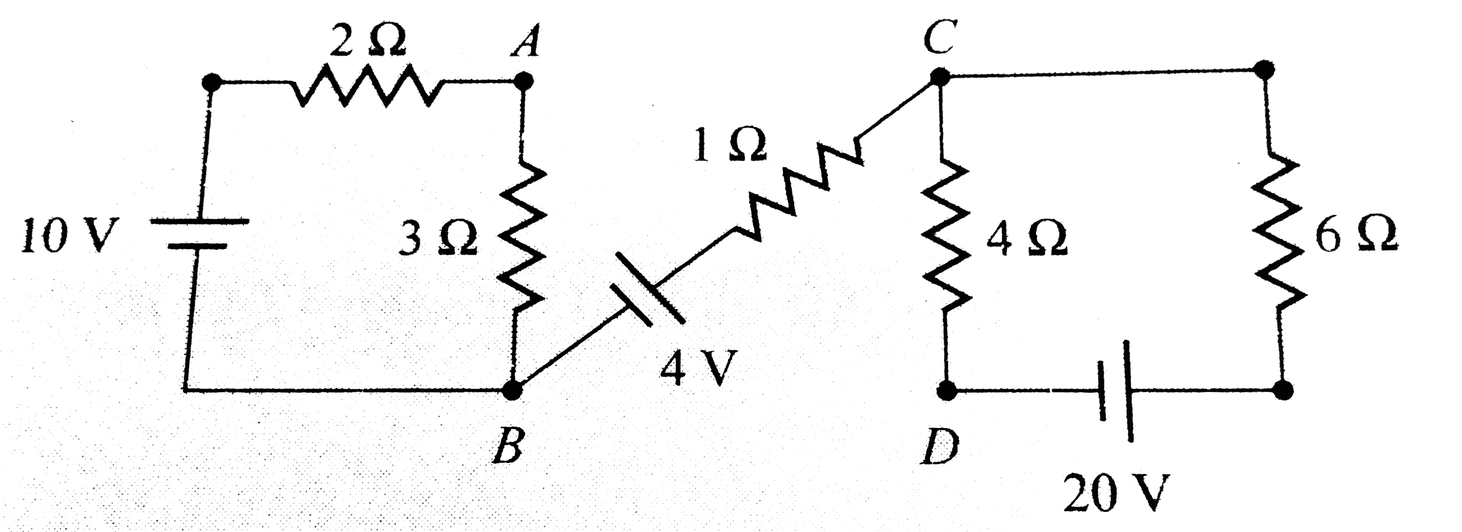
For the circuit shown in figure, determine the voltage across 4Ω resistors in volt ?

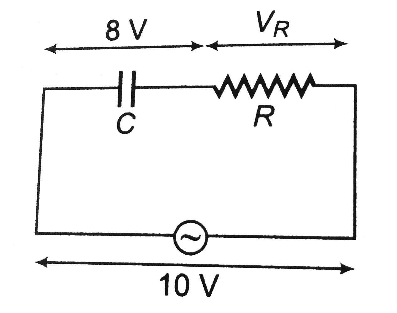
View SolutionIn a series C−R circuit shown in figureure, the applied voltage is 10V and the voltage across capacitor is found to8V. The voltage across R, and the phase difference between current and the applied voltage will respectively be
 .
.
View SolutionIn a series C−R circuit shown in figureure, the applied voltage is 10V and the voltage across capacitor is found to8V. The voltage across R, and the phase difference between current and the applied voltage will respectively be
 .
.
View SolutionThe diode used in the circuit shown in the adjacent figure has a constant voltage drop of 0.5V at all currents and a maximum power rating of 100mW.What should be the value of resistor R connected in series with the diode for obtaining maximum current?
View Solution(i) In the circuit shown in Figure below, calculate phase difference between the current and the supply voltage:
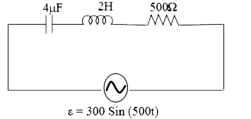
(ii) State whether current is leading or lagging behind the supply voltage
View SolutionIn the circuit shown in figure when the input voltage of the base resistance is 10 V . Find the values of Ib,Icandβ .
View Solution


