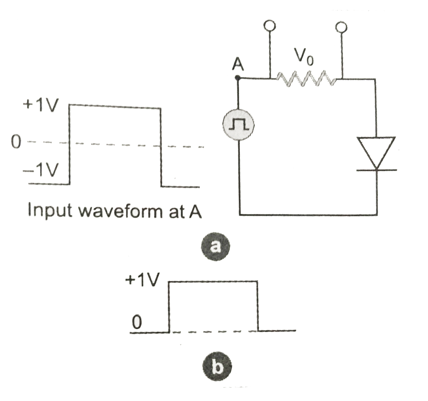
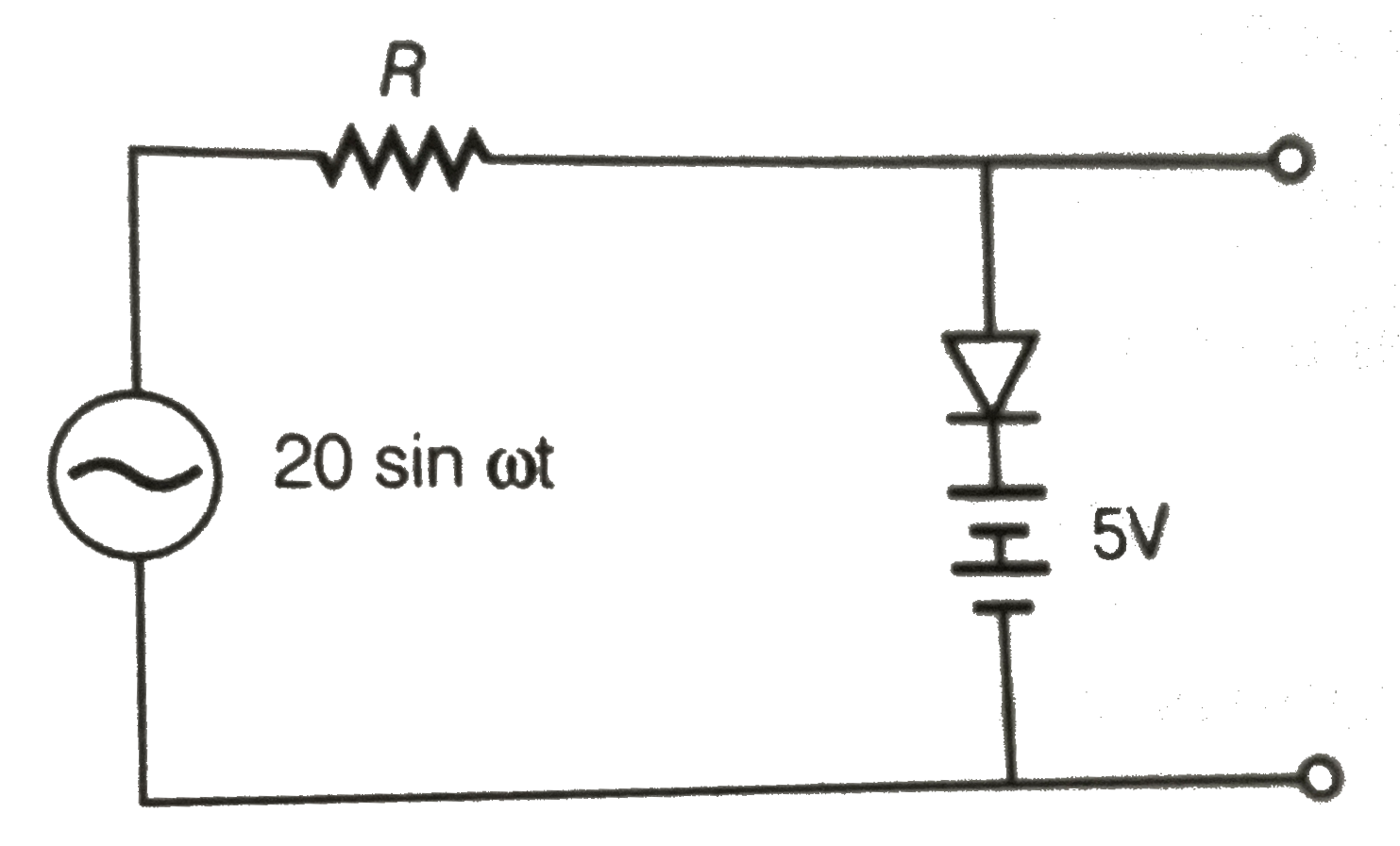
Draw the output waveform across the resistor (Fig.)


The correct Answer is:A
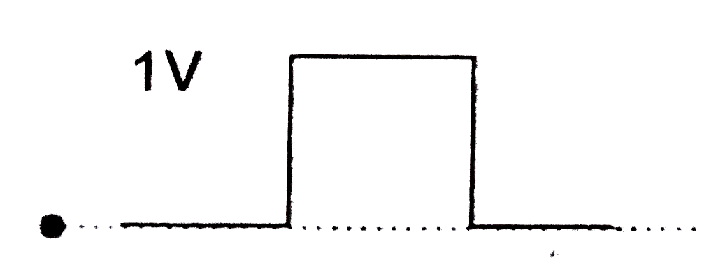
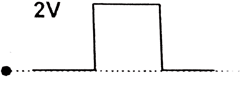
The p−n junction diode acts as a half wave rectifier, so the output waveform across the resistor is positvie half part.
Topper's Solved these Questions
- TEST PAPERSBOOK - FIITJEECHAPTER - TEST PAPERSEXERCISE - PHYSICS
747 Videos
- SIMPLE HARMONIC MOTIONBOOK - FIITJEECHAPTER - SIMPLE HARMONIC MOTIONEXERCISE - Assignment Problems (Objective) (Level-II)
20 Videos
- WORK, ENERGY AND POWER BOOK - FIITJEECHAPTER - WORK, ENERGY AND POWER EXERCISE - COMPREHENSIONS ( Comprehension-II)
5 Videos
Similar Questions
Knowledge Check
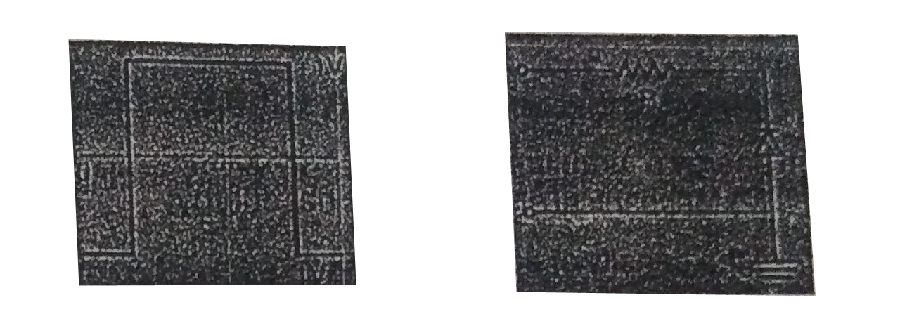
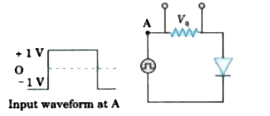
A square wave (-1 to +1V) is applied to a P-N junction diode as shown. Draw the output wave form across the diode which is assumed to be ideal-
 A
A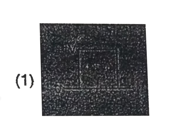 B
B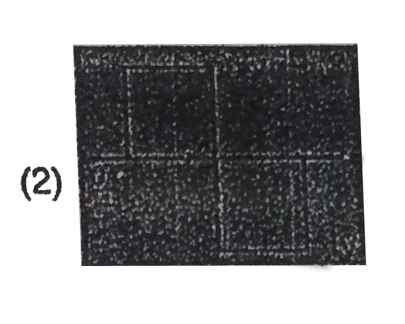 C
C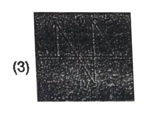 D
D
Draw and explain the output waveform across the load resistor R, if the input wave from is as shown in Fig.

View SolutionDraw and explain the output waveform across the load resistor R, if the input waveform is as shown in the given.
View SolutionThe circuit used to change alternating voltage to direct voltage is called rectifier
(a) with a neat diagram explain the working of a full wave rectifier having two diodes
(b) what is the output frequency of a full wave rectifier if the input frequency is 50 Hz
(c ) Draw the output waveform across the load resistance connected in the full wave rectifier circuit
View SolutionWrite the output waveform for the gates
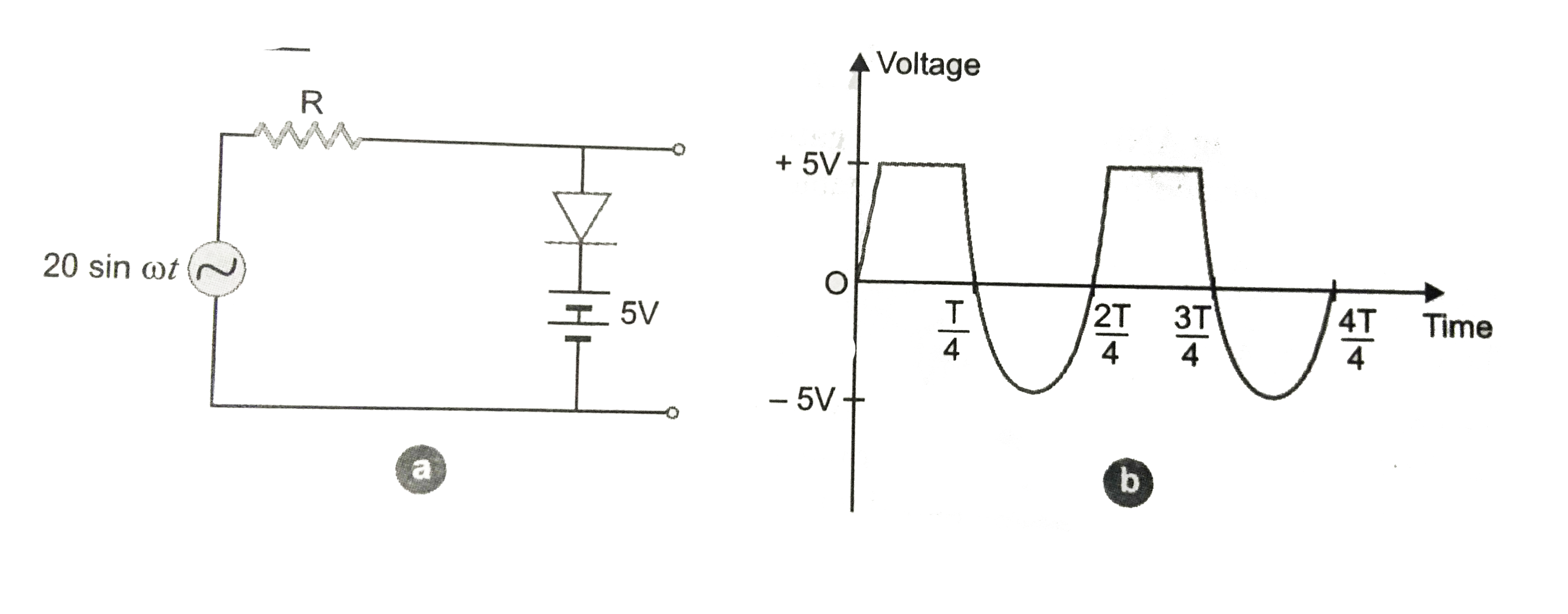
View SolutionAssuming the ideal diode, draw the output waveform for the circuit given in fig. (a), explain the waveform
View SolutionAssuming the ideal diode, draw the output waveform for the circuit given in Fig.Explain the waveform.
View Solution

(a) Draw the circuit diagram of reversed bias p-n junction.
(b). Draw the output wavefrom across diode in given circuit.
(c). Draw the truth table for the given logic gate.
View Solution

_S01_097_Q01.png)