Tommy sets up an electrical circuit as shown in the figure. He connects points P and Q with different materials.
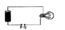
The bulb will light up when points P and Q are connected by a plate made of
Iron
Glass
Wood
Plastic
Step by step video & image solution for Tommy sets up an electrical circuit as shown in the figure. He connects points P and Q with different materials. The bulb will light up when points P and Q are connected by a plate made of by Physics experts to help you in doubts & scoring excellent marks in Class 7 exams.
Updated on:21/07/2023Topper's Solved these Questions
- ELECTRIC CURRENT AND ITS EFFECTSBOOK - BEIITIANSCHAPTER - ELECTRIC CURRENT AND ITS EFFECTSEXERCISE - CONCEPTIVE WORKSHEET
31 Videos
- ELECTRIC CURRENT AND ITS EFFECTSBOOK - BEIITIANSCHAPTER - ELECTRIC CURRENT AND ITS EFFECTSEXERCISE - SUMMATIVE WORKSHEET
23 Videos
- HEATBOOK - BEIITIANSCHAPTER - HEATEXERCISE - IIT JEE Worksheet (V. Matrix Matching)
4 Videos
Similar Questions
Brad sets up an electrical circuit as shown in the given figure. He connects points P and Q of the circuit with four different rods made of four different materials - glass, wood, copper, and asbestos.

The bulb in the circuit will not light up when points P and Q are connected with
View SolutionBrad sets up an electrical circuit as shown in the figure. He connects points P and Q of the circuit with four different rods made of four different materials - glass, wood, copper, and asbestos.

The bulb in the circuit will not light up when points P and Q are connected with
View Solution
Knowledge Check
The bulb will light up if the points X and Y are connected through ____ .
 AAn iron wireBA glass rodCPlastic rodDA wooden stick
There is a electric circuit as shown in the figure. Find potential difference between points a and b.
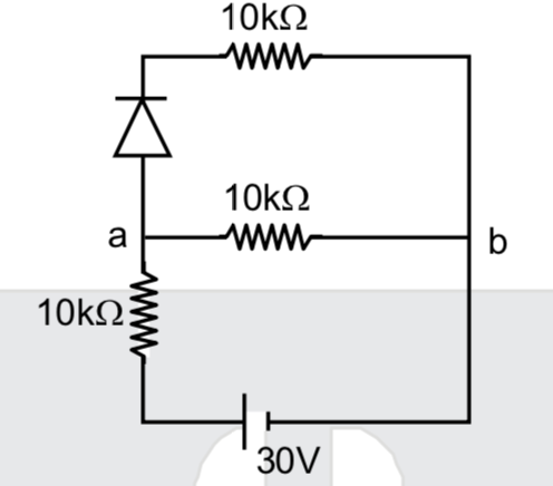 A3VB15VC10VD5V
Find VP−VQ in the circuit shown in figure.
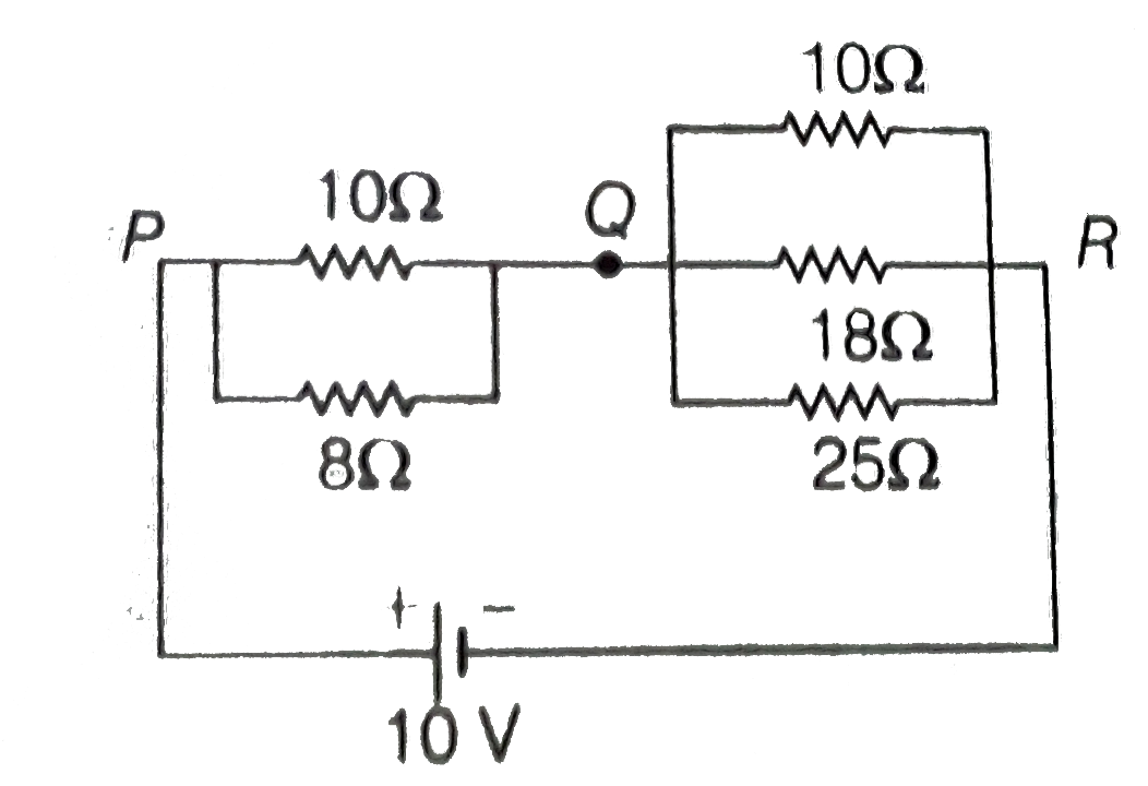 A6.68 VB8 VC4.65 VD7 V
Robert constructs an electrical circuit as shown in the given fgure. Four different points are labeled as P, Q, R, and S on the wooden rod.
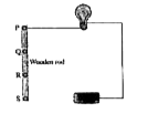
In the given circuit, the bulb will glow when the positive terminal of the battery is connected to the point
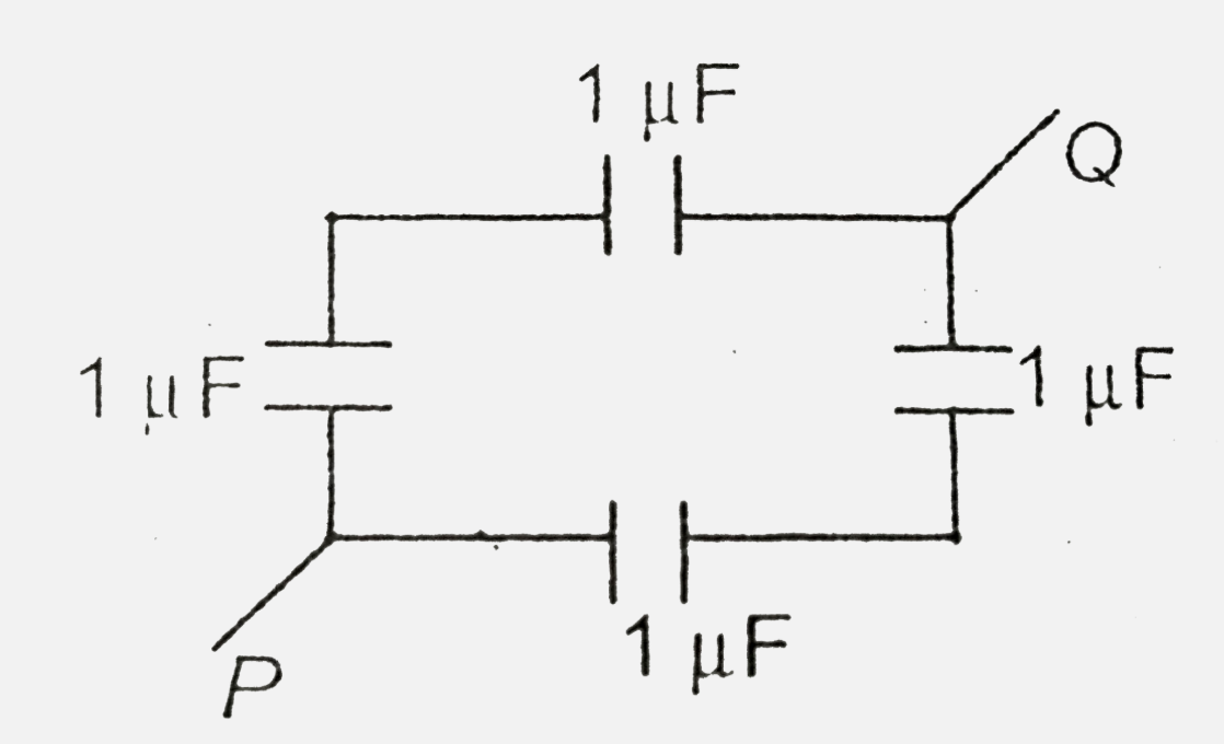
View SolutionFour capacitors are connected as shown in the figure. The equivalent capacitance between P and Q is
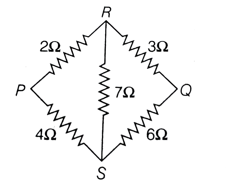
View SolutionFive resistance are connected as shown in the figure . The equivalent resistance between P and Q will be
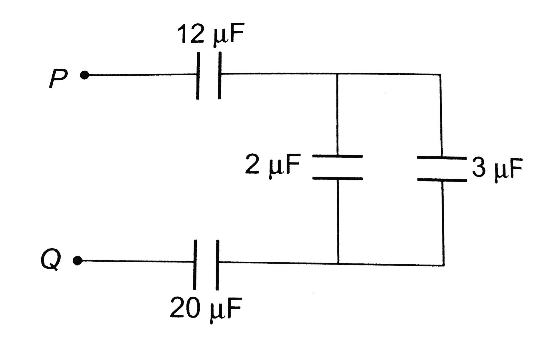
View SolutionIn the circuit diagram shown in the adjoining figure, the resultant capacitance between P and Q is
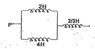
View SolutionThe equivalent inductance between points P and Q in the figure is :
View Solution
