Voltage drop across a p-n junction in forward bias is 0.5 V a battery of 2V is connected across the p-n junction such that the maximum current does not exceed 10 mA calculate the value of resistance to be connected across the diode
To solve the problem, we need to calculate the resistance that should be connected across the p-n junction diode to ensure that the maximum current does not exceed 10 mA when a 2V battery is connected.
1. Identify the Voltage Drop Across the Diode:
The voltage drop across the p-n junction in forward bias is given as 0.5 V.
2. Determine the Total Voltage Supplied by the Battery:
The battery voltage is given as 2 V.
3. Calculate the Net Voltage Across the Resistor:
The net voltage across the resistor can be calculated by subtracting the voltage drop across the diode from the battery voltage:
VR=Vbattery−Vdiode=2V−0.5V=1.5V
4. Use Ohm's Law to Calculate Resistance:
According to Ohm's Law, the relationship between voltage (V), current (I), and resistance (R) is given by:
V=I×R
Rearranging this formula to find resistance gives:
R=VI
Here, V is the net voltage across the resistor (1.5 V) and I is the maximum current (10 mA or 10×10−3A).
5. Substituting Values:
Substitute the values into the resistance formula:
R=1.5V10×10−3A=1.50.01=150Ω
6. Conclusion:
The value of the resistance to be connected across the diode to ensure that the maximum current does not exceed 10 mA is 150 Ω.
Final Answer:
The resistance to be connected across the diode is 150 Ω.
The voltage drop across the p-n junction in forward bias is given as 0.5 V.
The battery voltage is given as 2 V.
The net voltage across the resistor can be calculated by subtracting the voltage drop across the diode from the battery voltage:
VR=Vbattery−Vdiode=2V−0.5V=1.5V
According to Ohm's Law, the relationship between voltage (V), current (I), and resistance (R) is given by:
V=I×R
Rearranging this formula to find resistance gives:
R=VI
Here, V is the net voltage across the resistor (1.5 V) and I is the maximum current (10 mA or 10×10−3A).
Substitute the values into the resistance formula:
R=1.5V10×10−3A=1.50.01=150Ω
The value of the resistance to be connected across the diode to ensure that the maximum current does not exceed 10 mA is 150 Ω.
The resistance to be connected across the diode is 150 Ω.
Topper's Solved these Questions
- SEMICONDUCTOR ELECTRONICS METERIALS DEVICES AND SIMPLE CIRCUITS BOOK - MODERN PUBLICATIONCHAPTER - SEMICONDUCTOR ELECTRONICS METERIALS DEVICES AND SIMPLE CIRCUITS EXERCISE - CONCEPUAL QUESTIONS
37 Videos
- SEMICONDUCTOR ELECTRONICS METERIALS DEVICES AND SIMPLE CIRCUITS BOOK - MODERN PUBLICATIONCHAPTER - SEMICONDUCTOR ELECTRONICS METERIALS DEVICES AND SIMPLE CIRCUITS EXERCISE - TOUGH & TRICKY PROBLEMS
10 Videos
- SEMICONDUCTOR ELECTRONICS METERIALS DEVICES AND SIMPLE CIRCUITS BOOK - MODERN PUBLICATIONCHAPTER - SEMICONDUCTOR ELECTRONICS METERIALS DEVICES AND SIMPLE CIRCUITS EXERCISE - CHAPTER PRACTICE TEST FOR BOARD EXAMINATION
12 Videos
- RAY OPTICS AND OPTICAL INSTRUMENTSBOOK - MODERN PUBLICATIONCHAPTER - RAY OPTICS AND OPTICAL INSTRUMENTSEXERCISE - CHAPTER PRACTICE TEST
14 Videos
- WAVE OPTICALBOOK - MODERN PUBLICATIONCHAPTER - WAVE OPTICALEXERCISE - CHAPTER PRACTICE TEST
7 Videos
Similar Questions
When a 12V battery is connected across an unknown resistor, there is a current of 2.5mA in the circuit. Find the value of the resistance of the resistor.
View SolutionWhen a 12V battery is connected across an unknown resistor, there is a current of 2.5mA in the circuit. Find the value of the resistance of the resistor.
View Solution
Knowledge Check
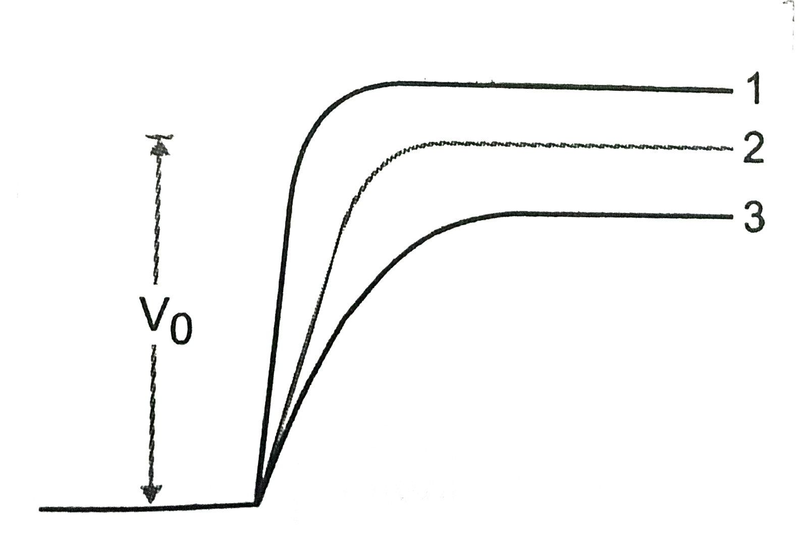
In Fig . V0 is the potential barrier across a p-n junction, when no battery is connected across the junction
 A1 and 3 both correspond to forward bias of junctionB3 corresponds to forward bias of junction and 1 corresponds to reverse bias of junctionC1 corresponds to forward bias and 3 corresponds to reverse bias of junctionD3 and 1 both correspond to reverse bias of junction
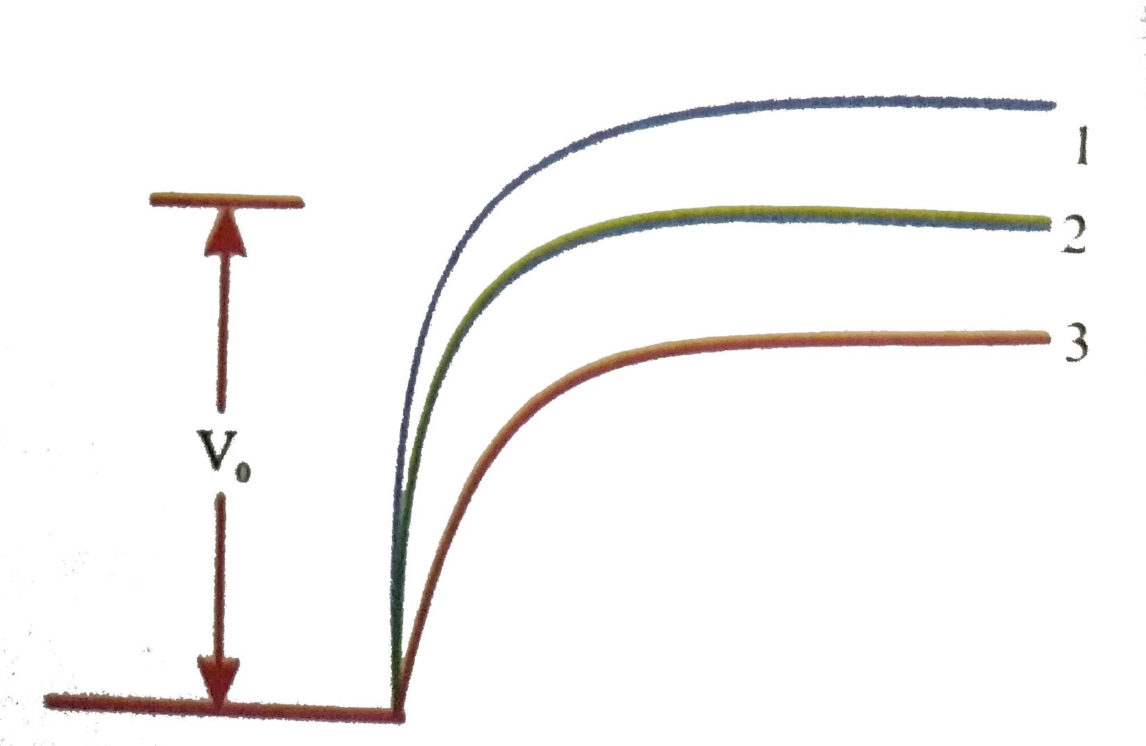
In Fig. V0 is the potential barrier across a p−n junction, when no battery is connected across the junction :
 .A1 and 3 both correspond is forward bias of junctionB3 corresponds to forward bias of junction and 1 corresponds to reverse bias junctionC1 corresponds to forward bias and 3 corresponds to reverse bias junctionD3 and 1 both correspond to reverse bias and 3 corresponds to revers bias of junction
When a 4V battery is connected across an unknown resistor there is a current of 100 mA in the circuit. The value of the resistance of the resistor is:
A4ωB40ωC400ωD0.4ω
When a 12V battery is connected across an unknown resistor, there is a current of 2.5mA in the circuit. Find the value of the resistance of the resistor.
View SolutionWhen a 12 V battery is connected across an unknown resistor, there is a current of 2.5 mA in the circuit. Find the value of the resistance of the resistor.
View SolutionCan the potential barrier across a p-n junction be measured by simply connecting a voltmeter across the junction ?
View SolutionWhen a 4 V battery is connected across an unknown resistor there is a current of 100 mA in the circuit. The value of the resistance of the resistor is
View SolutionWhen a p-n junction diode is forward biased, the flow of current across the junction is mainly.
View Solution
