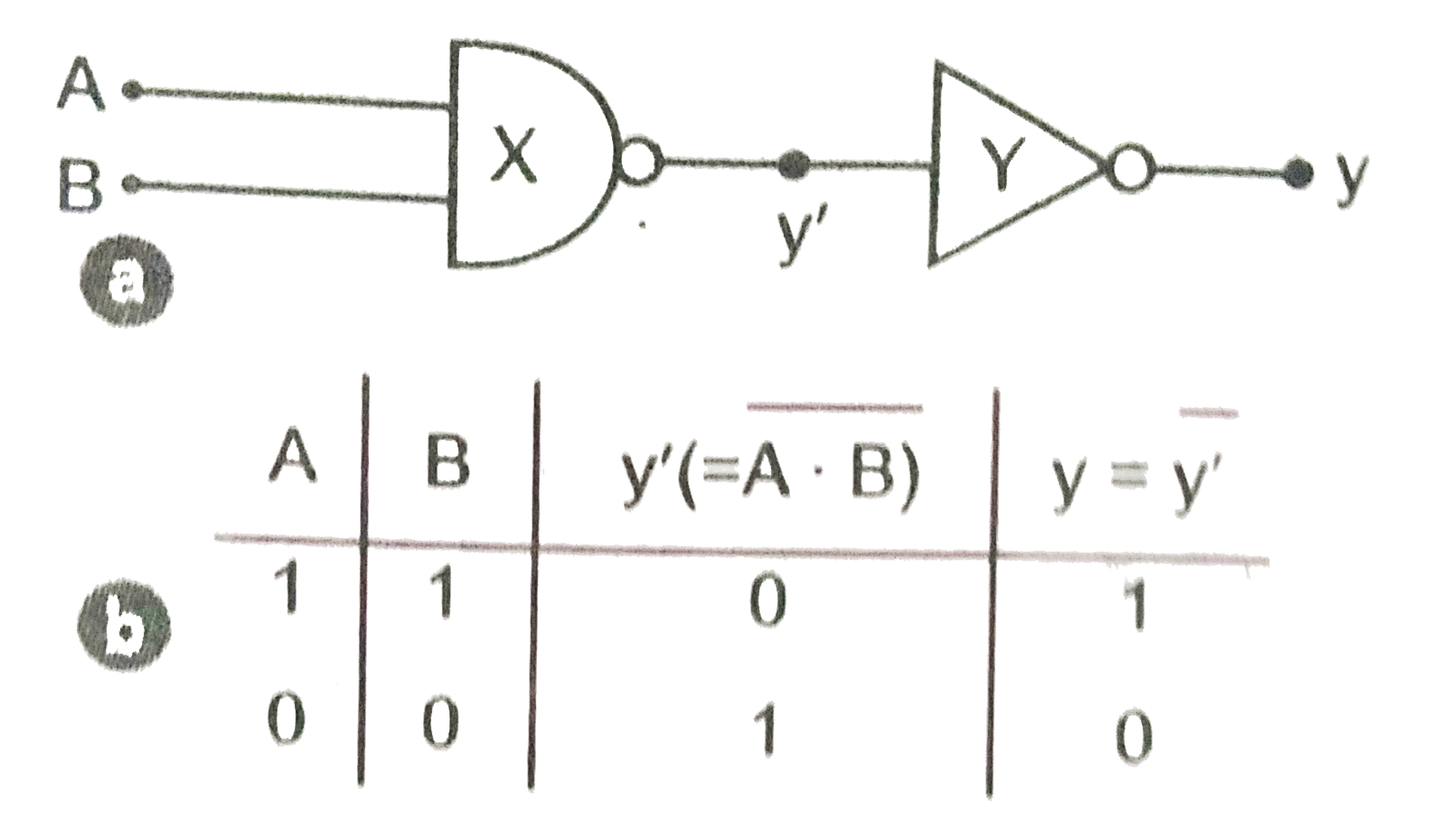
Identify the logic gates marked P and Q in the circuit Fig. Write the truth table for this combination.

Topper's Solved these Questions
- SEMICONDUCTOR ELECTRONICS METERIALS DEVICES AND SIMPLE CIRCUITS BOOK - MODERN PUBLICATIONCHAPTER - SEMICONDUCTOR ELECTRONICS METERIALS DEVICES AND SIMPLE CIRCUITS EXERCISE - CONCEPUAL QUESTIONS
37 Videos
- SEMICONDUCTOR ELECTRONICS METERIALS DEVICES AND SIMPLE CIRCUITS BOOK - MODERN PUBLICATIONCHAPTER - SEMICONDUCTOR ELECTRONICS METERIALS DEVICES AND SIMPLE CIRCUITS EXERCISE - TOUGH & TRICKY PROBLEMS
10 Videos
- SEMICONDUCTOR ELECTRONICS METERIALS DEVICES AND SIMPLE CIRCUITS BOOK - MODERN PUBLICATIONCHAPTER - SEMICONDUCTOR ELECTRONICS METERIALS DEVICES AND SIMPLE CIRCUITS EXERCISE - CHAPTER PRACTICE TEST FOR BOARD EXAMINATION
12 Videos
- RAY OPTICS AND OPTICAL INSTRUMENTSBOOK - MODERN PUBLICATIONCHAPTER - RAY OPTICS AND OPTICAL INSTRUMENTSEXERCISE - CHAPTER PRACTICE TEST
14 Videos
- WAVE OPTICALBOOK - MODERN PUBLICATIONCHAPTER - WAVE OPTICALEXERCISE - CHAPTER PRACTICE TEST
7 Videos
Similar Questions
Write the truth table for the given combination of gates

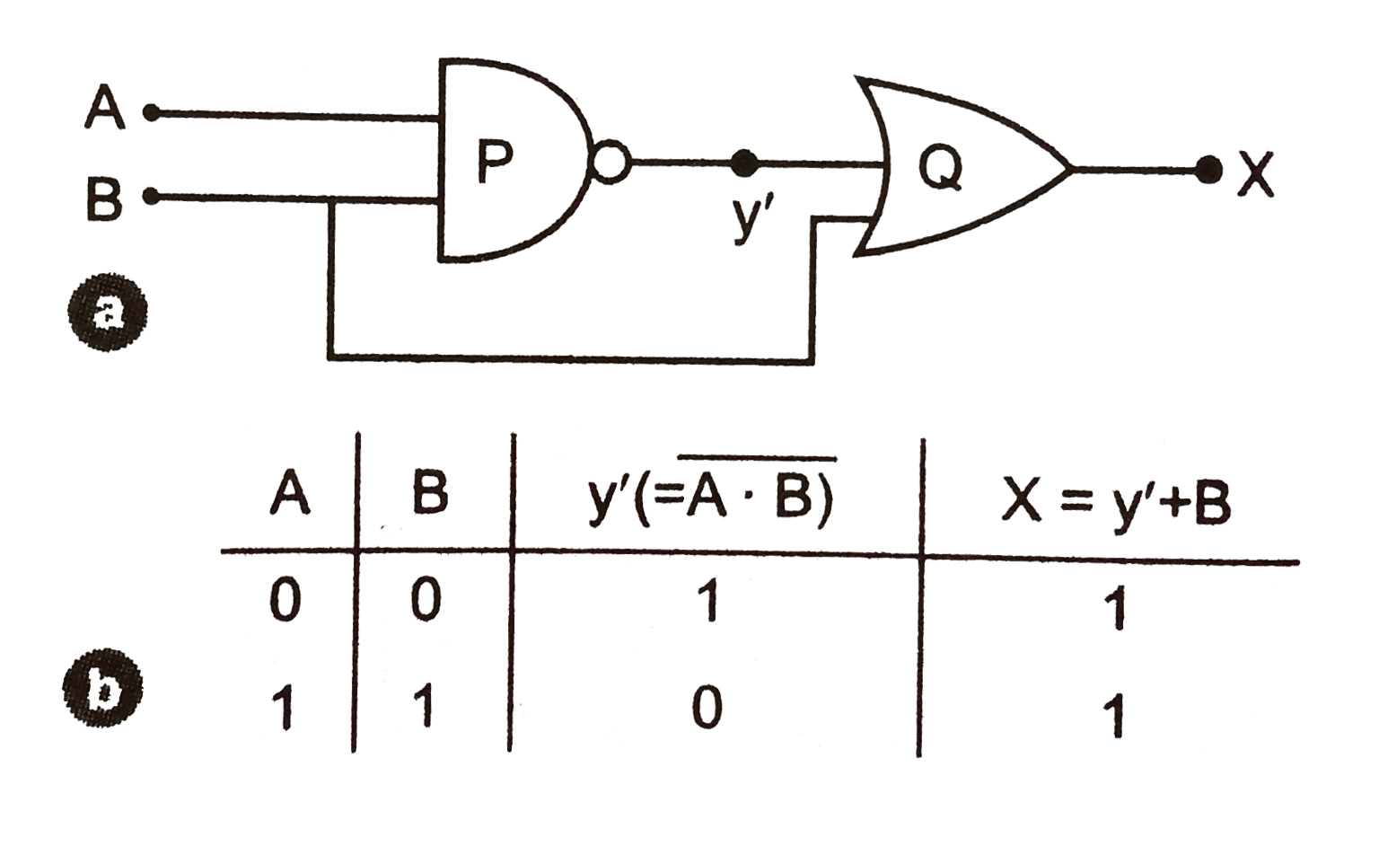
View SolutionIdentify the logic gates marked P and Q in the given logic circuit Fig. Write down then output at X for the inputs
(i) A=0,B=0 and (ii) A=1,B=1.
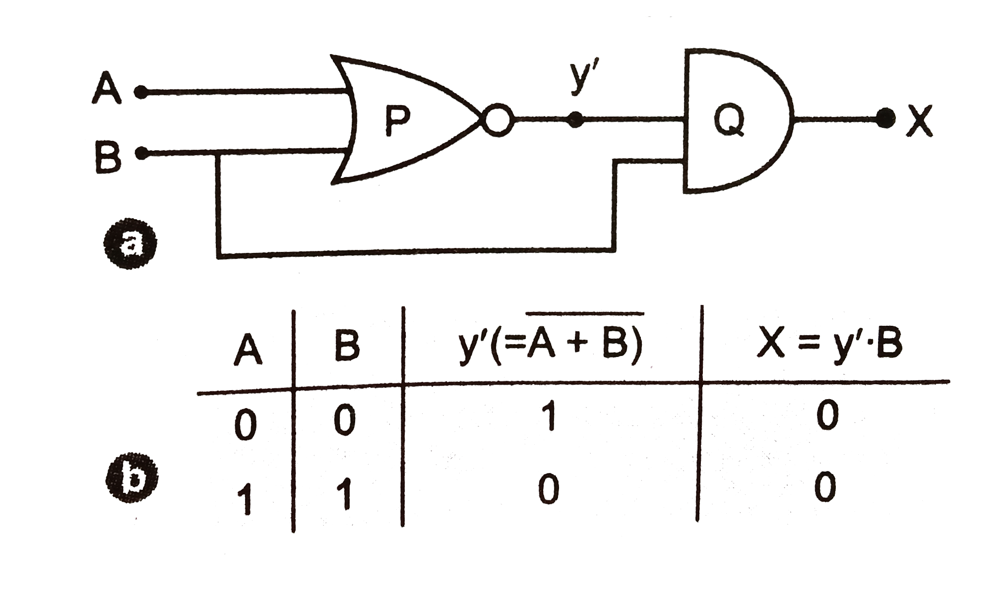
View SolutionIdentify the logic gate markeed P and Q in the given logic circuit Fig . Write down the output at X for the inputs
(i) A=0,B=0 and (ii) A=1,B=1.
View SolutionIdentify the gates P and Q shown in the figure. Write the truth table for the combination of the gates shown.

Name the equivalent gate representing this circuit and write its logic symbol.
View Solution(i) Identify the logic gates marked P and Q in the given logic circuit Fig.

(ii) Write down the output at X for the inputs A=0,B=0 and A=1,B=1.
View Solution(i) Identify the logic gates marked P and Q in the given logic circuit.
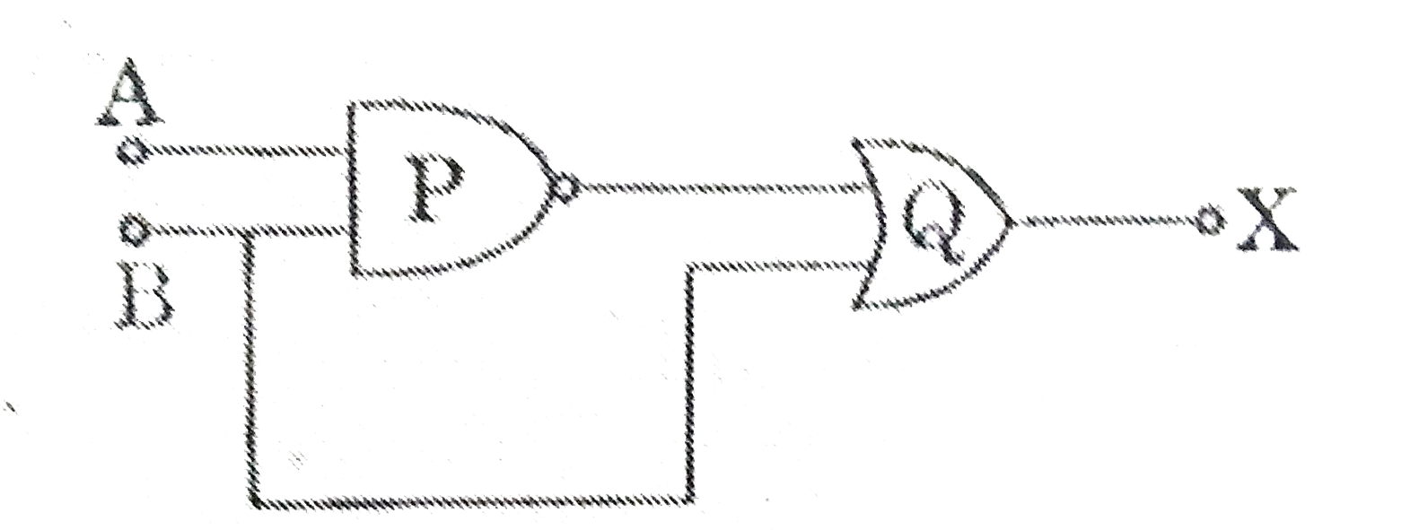
(ii) Write down the output at X for the inputs A = 0 , B = 0 and A = 1 , B = 1.
View SolutionWrite the truth table of AND gate.
View SolutionIdentify the logic gates marked P and Q in the given logic circuit. Write down the Boolean expression for this logic circuit and truth table.

View SolutionWrite the truth table for the circuit shown in Fig.
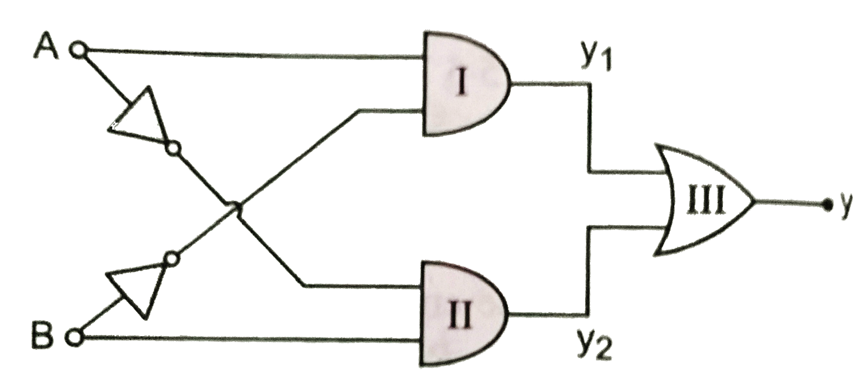
View SolutionIdentify the logic gates marked X,Y in the given logic circuit Fig. Write down then output at y, when
(i) A=0,B=0 and (ii) A=1,B=1.
View Solution

