Complete Solutions to Capacitor Circuits of chapter ELECTRIC POTENTIAL & CAPACITANCE of Class 12 book with complete answers and questions
| Class 12 | PHYSICS |
| Chapter | ELECTRIC POTENTIAL & CAPACITANCE |
| A2Z | Capacitor Circuits |
| Number Of Questions | 52 |
| Academic Year | 2023-24 |
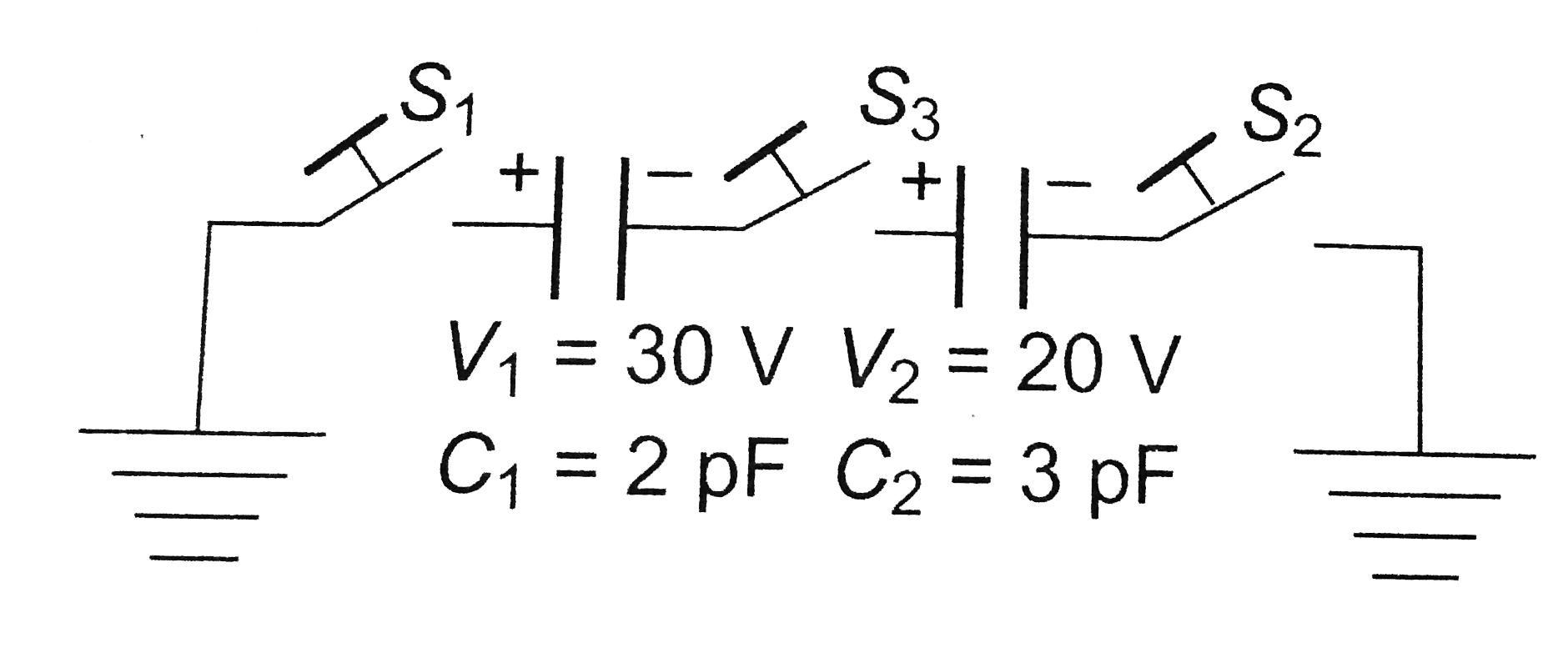
For the circuit shown in figure, which of the following statements is true ?
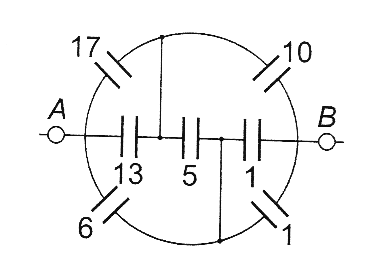
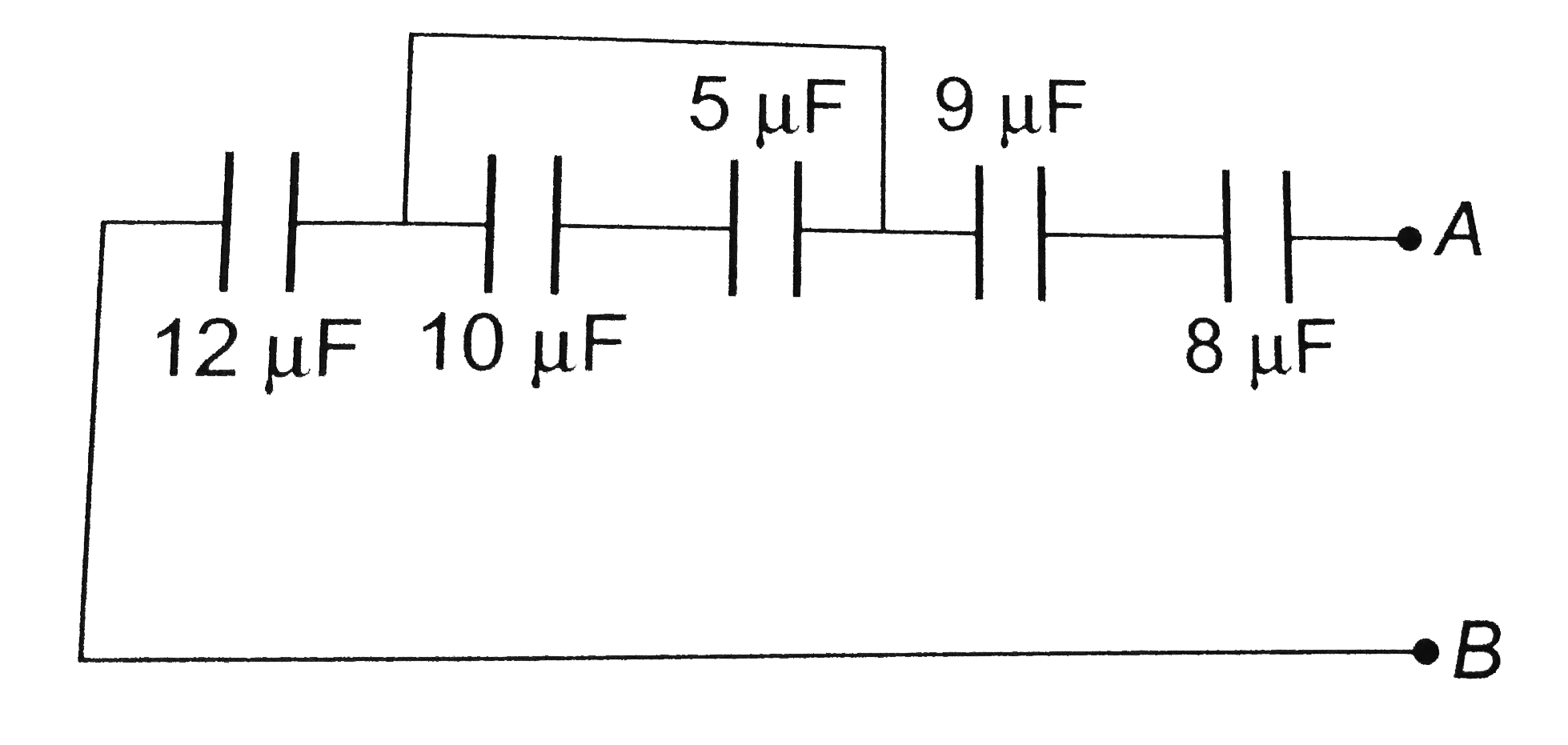
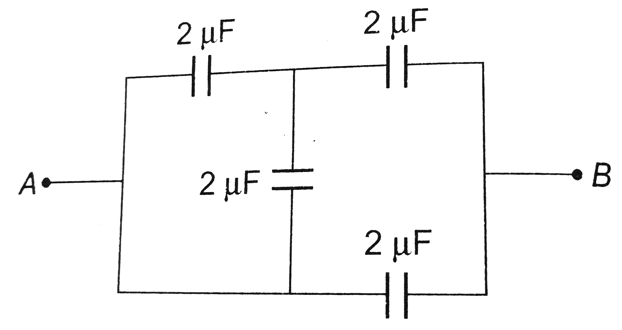
View SolutionFind equivalent capacitance across `AB` (all capacitances in `muF`)
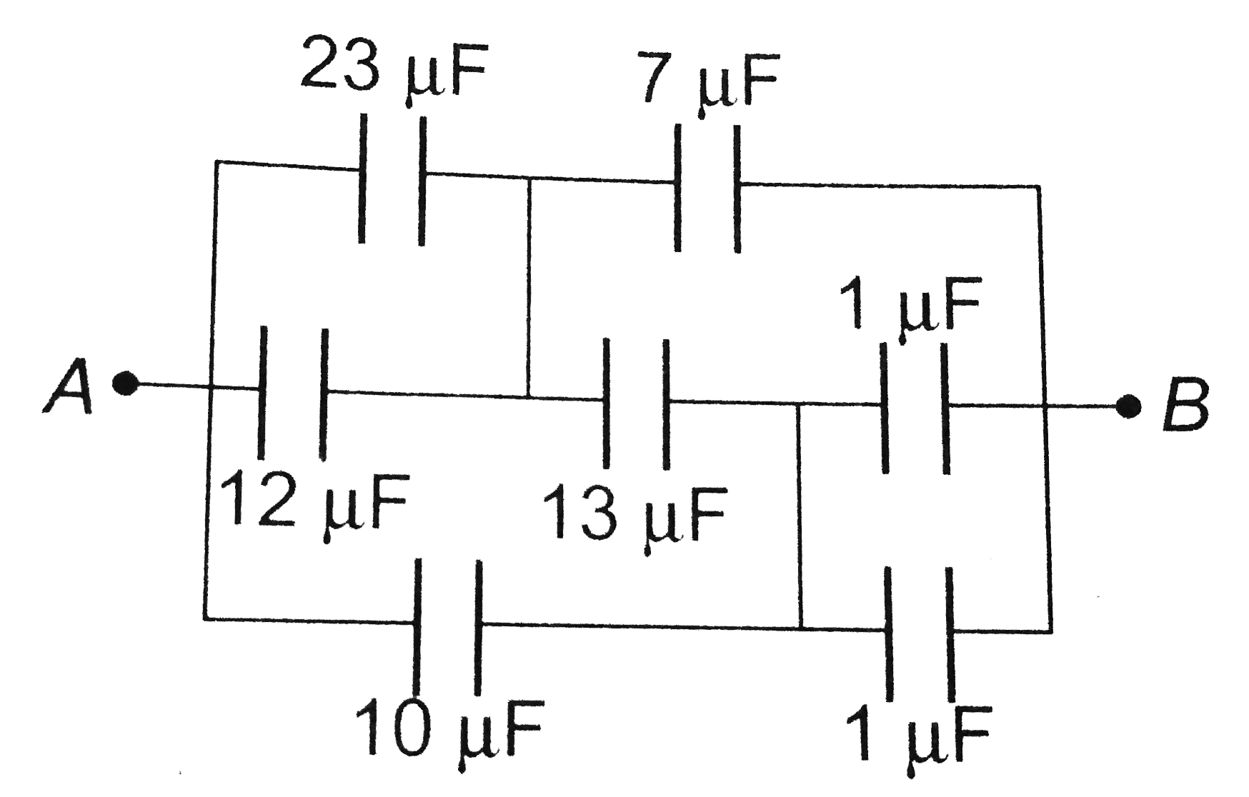
View SolutionFind the equivalent capacitance across `A & B`
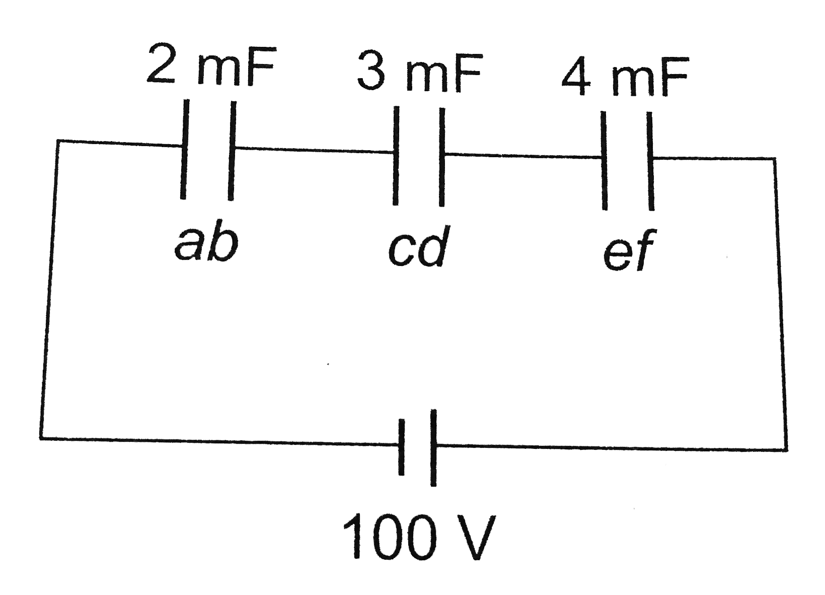
View SolutionThree capacitors are connected to `D.C` source of `100` volts shown in the adjoining figure. If the charge accumulated on plates of `C_(1), C_(2)` and `C_(3)` are `q_(a), q_(b), q_(c ), q_(d), q_(e)` and `q_(f)` respectively, then
View SolutionThree capacitors each of capacitance `1 muF` are connected in parallel. To this combination, a fourth capacitor capacitance `1 muF` is connected in series. The resultant capacitance of the system is
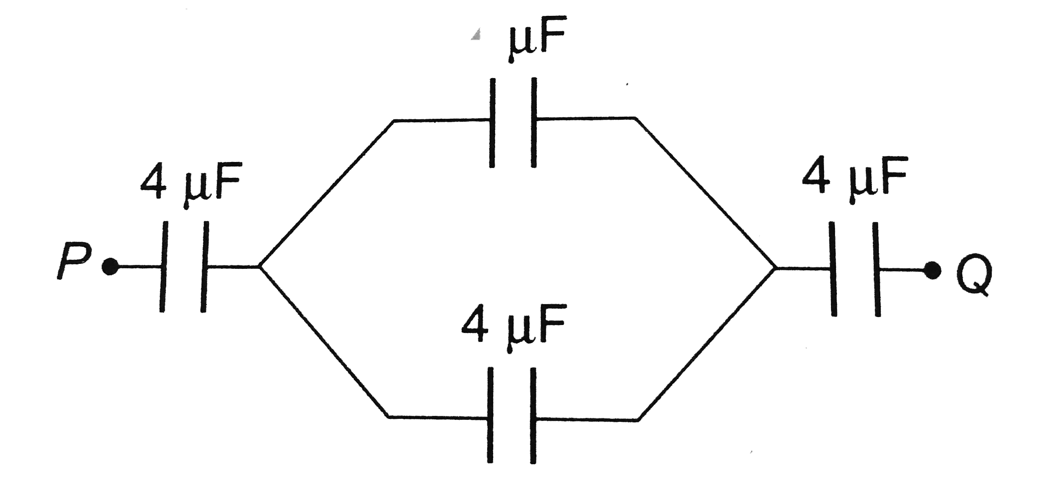
View SolutionFour condensers each of capacity `4mF` are connected as shown in figure. `V_(P) - V_(Q) = 15` volts. The energy stored in the system is
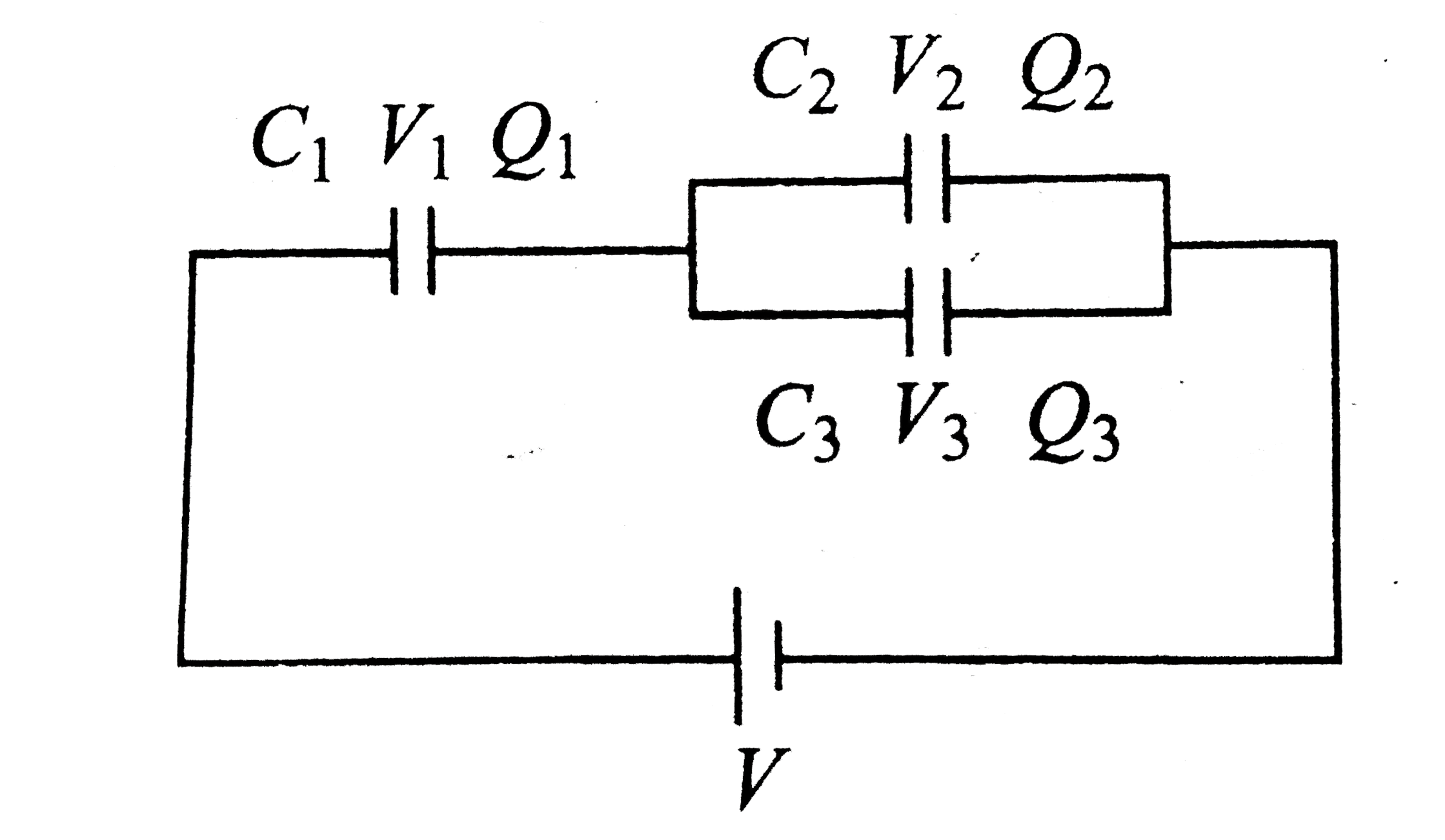
View SolutionIn three capacitors `C_(1),C_(2)`, and `C_(3)`, are joined to a battery, With symbols having their usual meaning, the correct conditions will be
 .
.
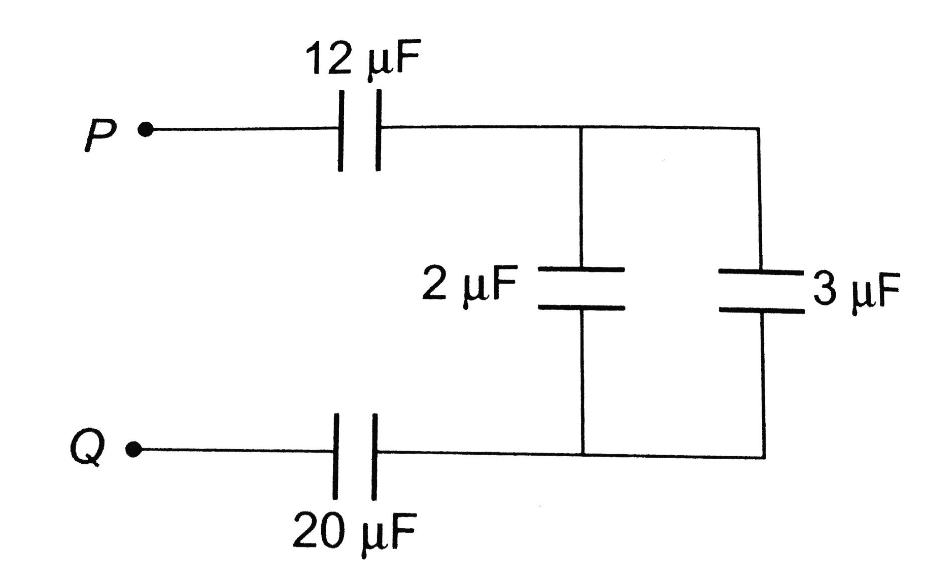
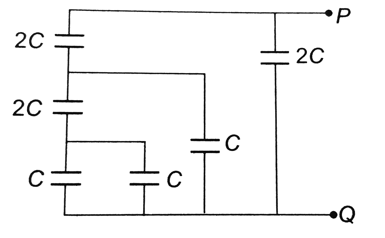
View SolutionIn the circuit diagram shown in the adjoining figure, the resultant capacitance between `P` and `Q` is
View SolutionIf three capacitors each of capacity `1 muF` are connected in such a way that the resultant capacity is `1.5 muF`, then
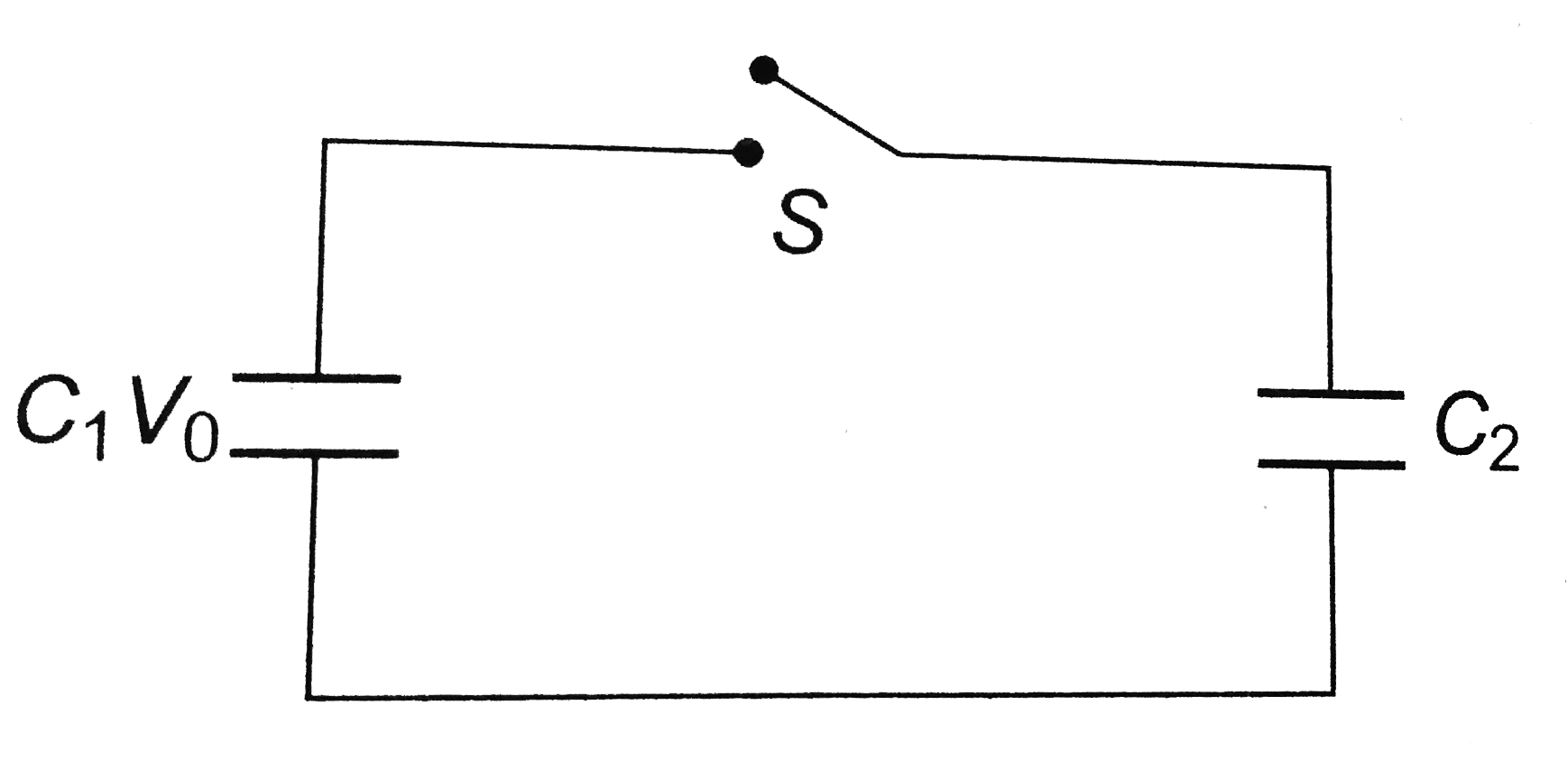
View SolutionA capacitor of capacity `C_(1)` is charged to the potential of `V_(0)`. On disconnecting with the battery, it is connected with a capacity `C_(2)` as shown in the adjoining figure. The ratio of energies before and after the connection of switch `S` will be
View SolutionFour capacitors of each of capacity `3 muF` are connected as shown in the adjoining figure. The ratio of equivalent capacitance between `A` and `B` and between `A` and `C` will be
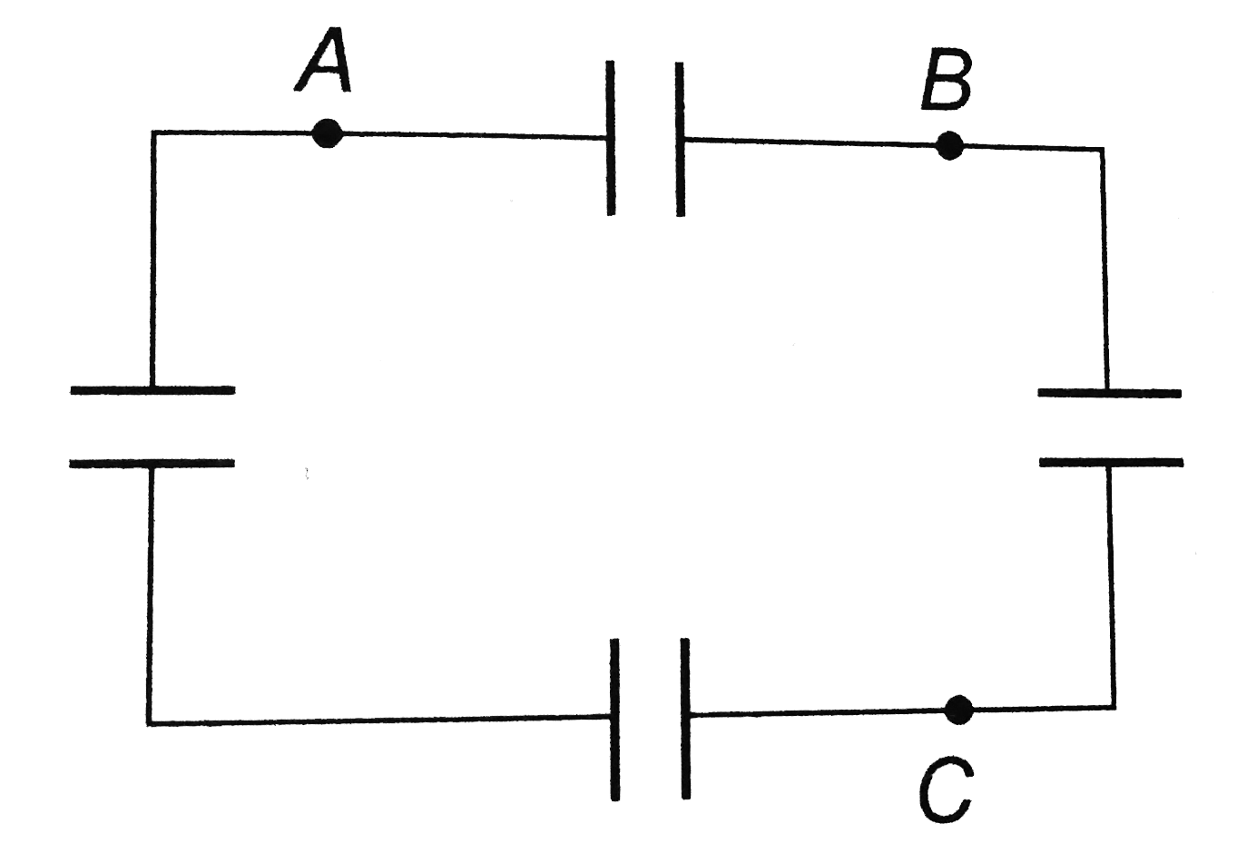
View SolutionFour condensers are joined as shown in the adjoining figure. The capacity of each is `8 muF`. The equivalent capacity between the points `A` and `B` will be
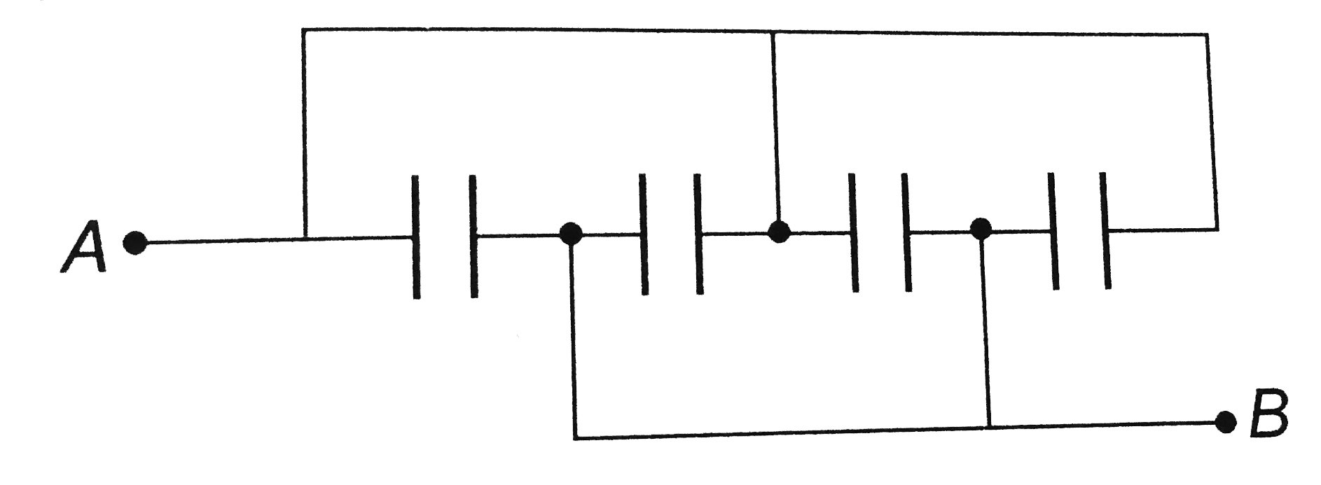
View SolutionThe capacities and connection of five capacitors are shown in the adjoining figure. The potential difference between the points `A` and `B` is `60` volts. Then the equivalent capacity between `A` and `B` and the charge on `5 muF` capacitance will be respectively
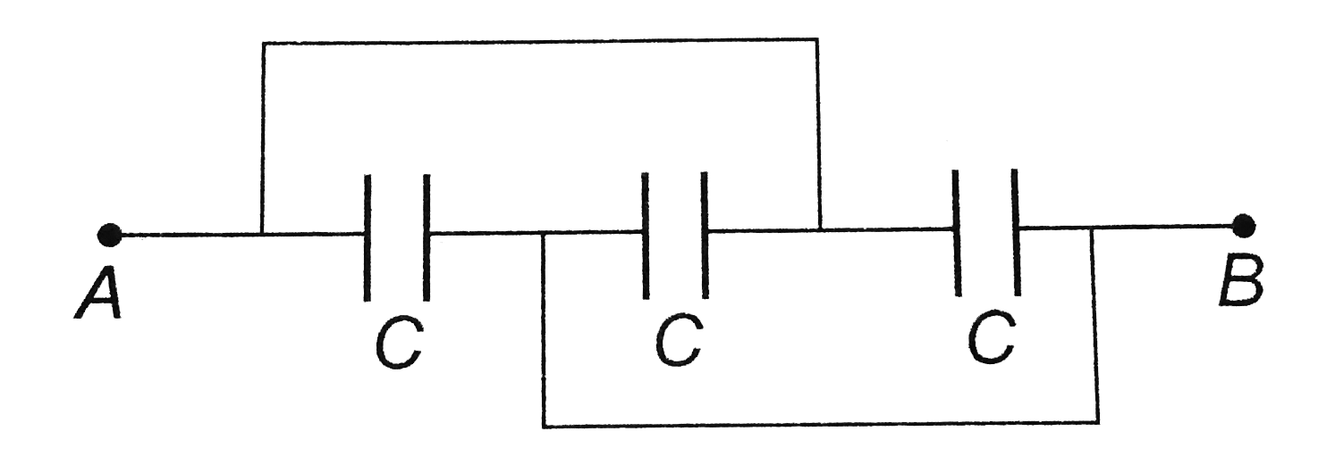
View SolutionThree equal capacitors, each with capacitance `C` are connected as shown in figure. Then the equivalent capacitance between `A` and `B` is
View SolutionIn the adjoining figure, four capacitors are shown with their respective capacities and the `P.D.` applied. The charge and the `P.D`. Across the `4muF` capacitor will be
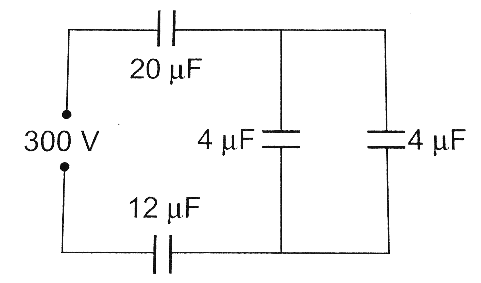
View SolutionA `4 muF` condenser is connected in parallel to another condenser of `8 muF`. Both the condensers are then connected in series with a `12 muF` condenser and charged to `20` volts. The charge on the plate of `4muF` condenser is
View SolutionIn the connection shown in the adjoining figure, the equivalent capacity between `A` and `B` will be
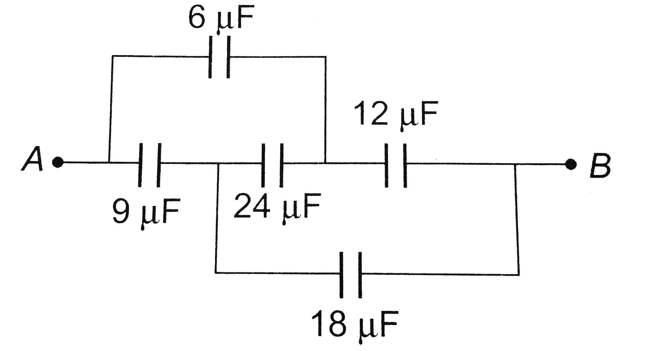
View SolutionThe resultant capacitance between `A` and `B` in the following figure is equal to
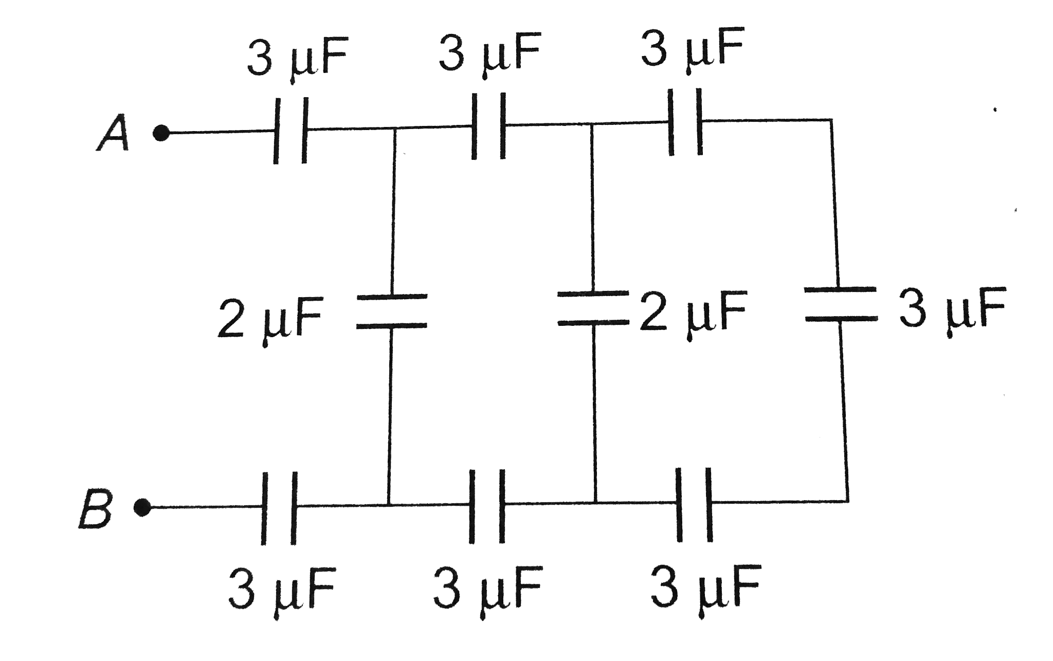
View SolutionIn the following circuit, the resultant capacitance between `A` and `B` is `1muF`. Then value of `C` is
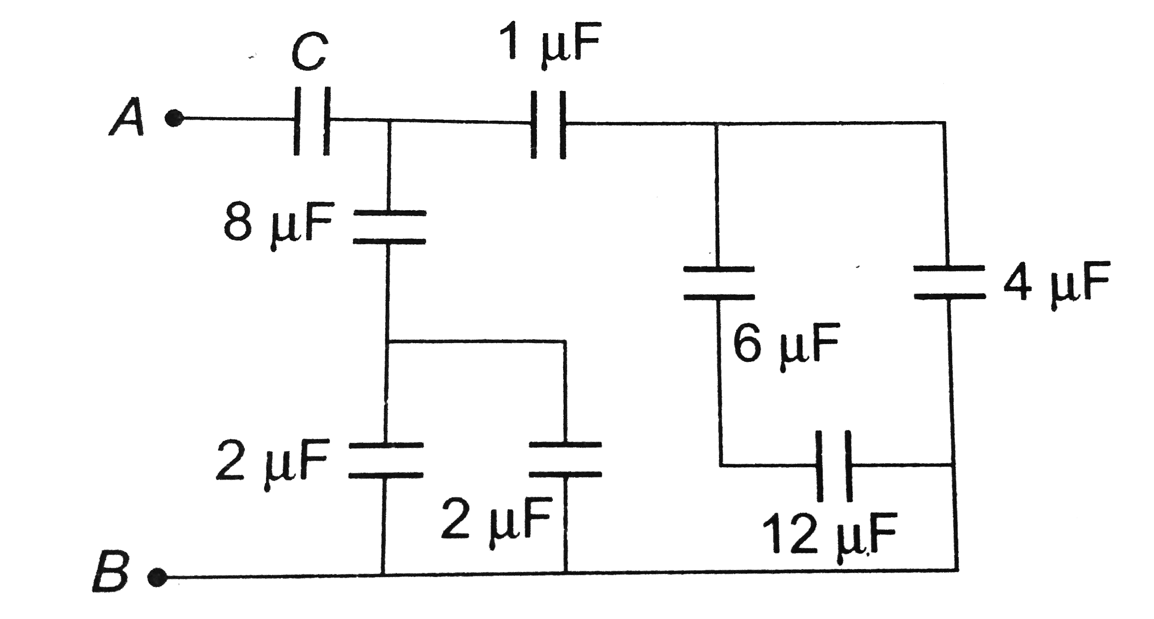
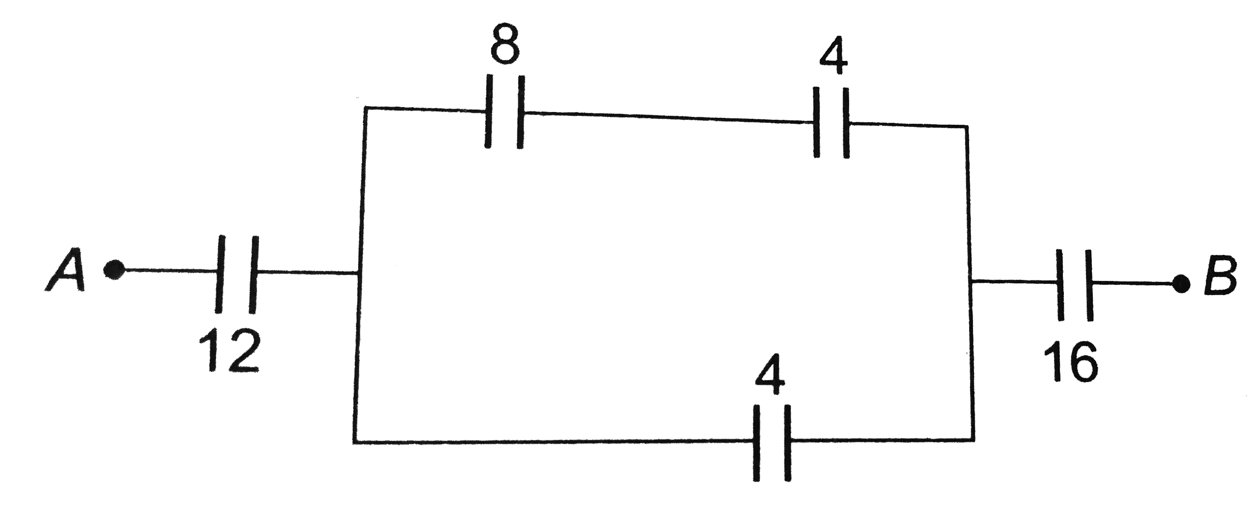
View SolutionWhat is the equivalent capacitance between `A` and `B` in the given figure (all are in farad )?
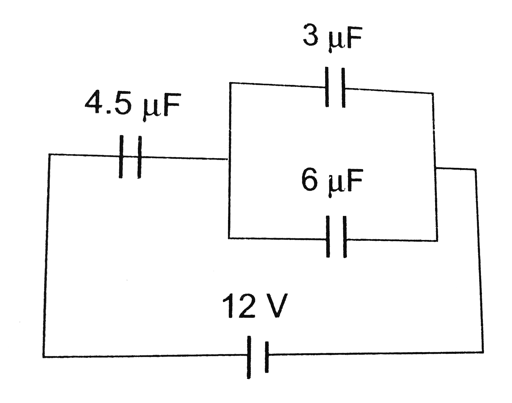
View SolutionIn the circuit shown in the figure, the potential difference across the `4.5 muF` capacitor is
View SolutionMinimum number of capacitors of `2muF` capacitance each required to obtain a capacitor of `5muF` will be
View SolutionThe total capacity of the system of capacitors shown in the adjoining figure between the points `A` and `B` is
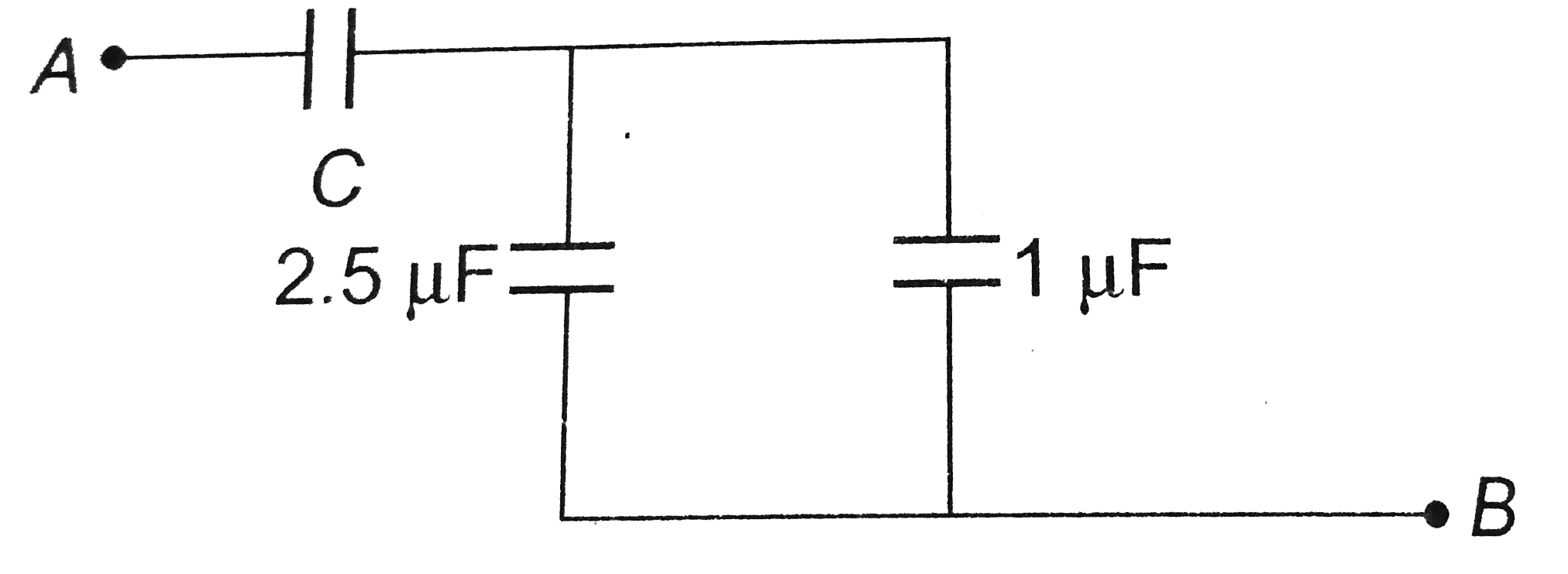
View SolutionThe equivalent capactiance between `A` and `B` in the figure is `1 muF`. Then the value of capacitance `C` is
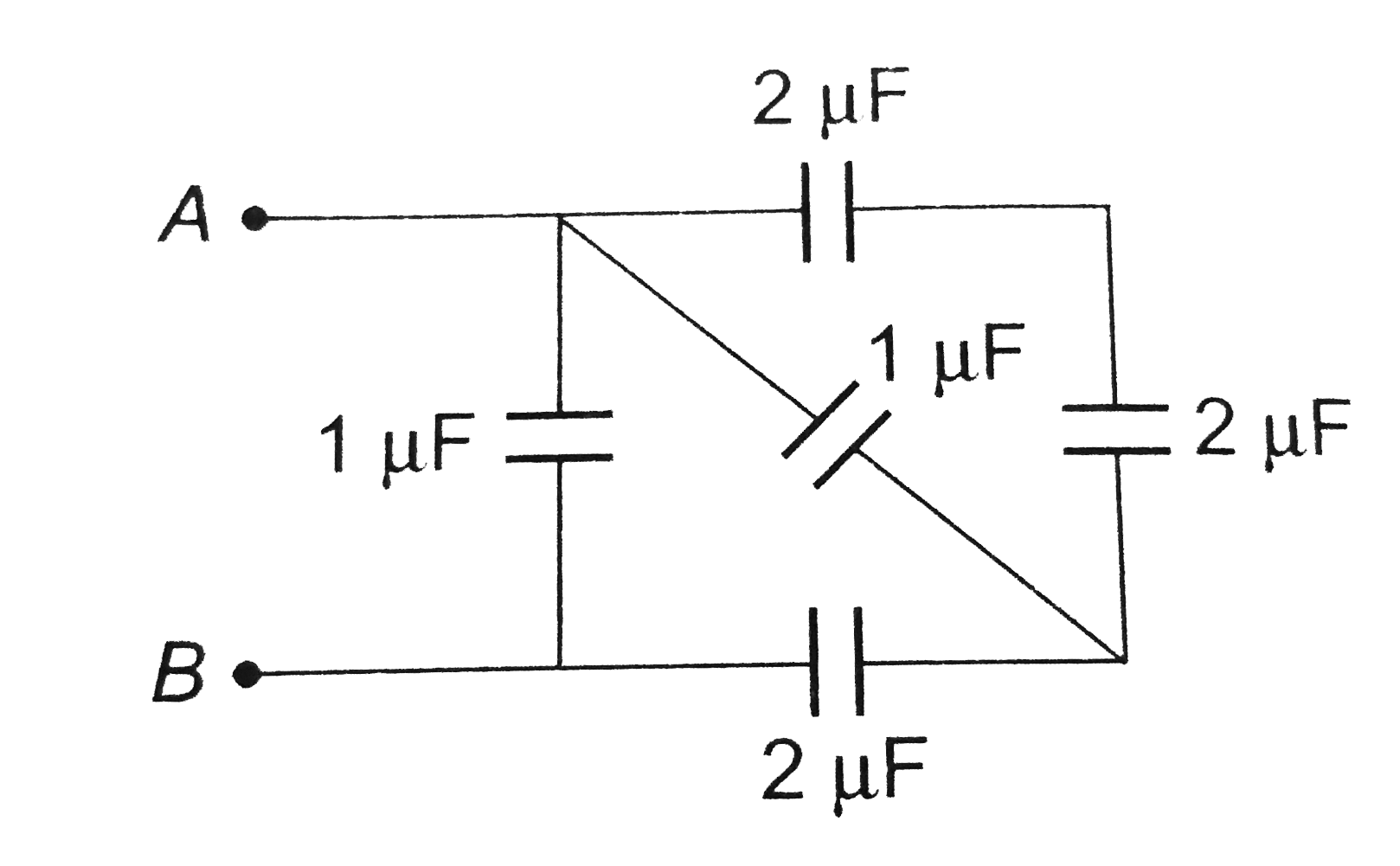
View SolutionFour capacitors are connected in a circuit as shown in the figure. The effective capacitance in `muF` between points `A` and `B` will be
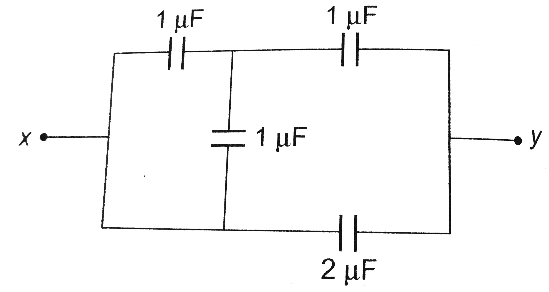
View SolutionFour capaciotrs are connected as shown in the figure. Their capacities are indicated in the figure. The effective capacitance between points `x` and `y` is (in `muF`)
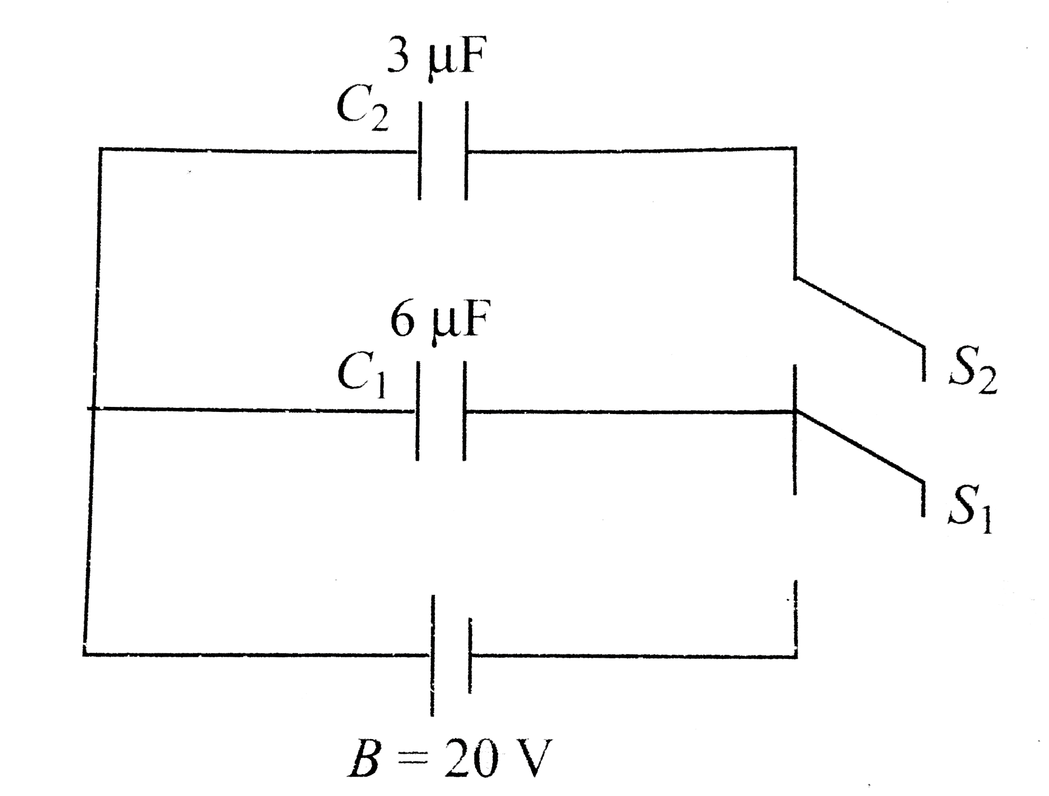
View SolutionIn the circuit shown in, `C_(1)=6 muF, C_(2)=3 muF`, and battery `B=20 V`. The switch `S_(1)` is first closed. It is then opened, and `S _(2)` is closed. What is the final charge on `C_(2)`
 .
.
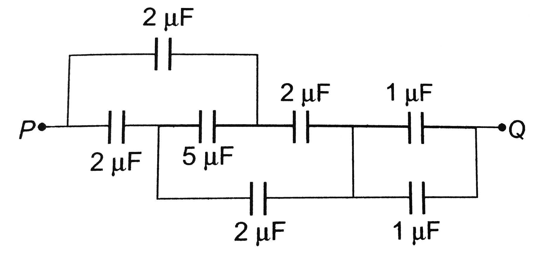
View SolutionThe effective capacitance between the points `P` and `Q` of the arrangement shown in the figure is
View SolutionTwo condensers `C_(1)` and `C_(2)` in a circuit are joined as shown in . The potential fo point `A` is ` V_1` and that of `B` is ` V_2` . The potential of point `D` will be `

View SolutionTo obtain `3 mF` capacity from three capacitors of `2mF` each, they will be arranged
View SolutionWhat is the effective capacitance between points `X` and `Y` ?
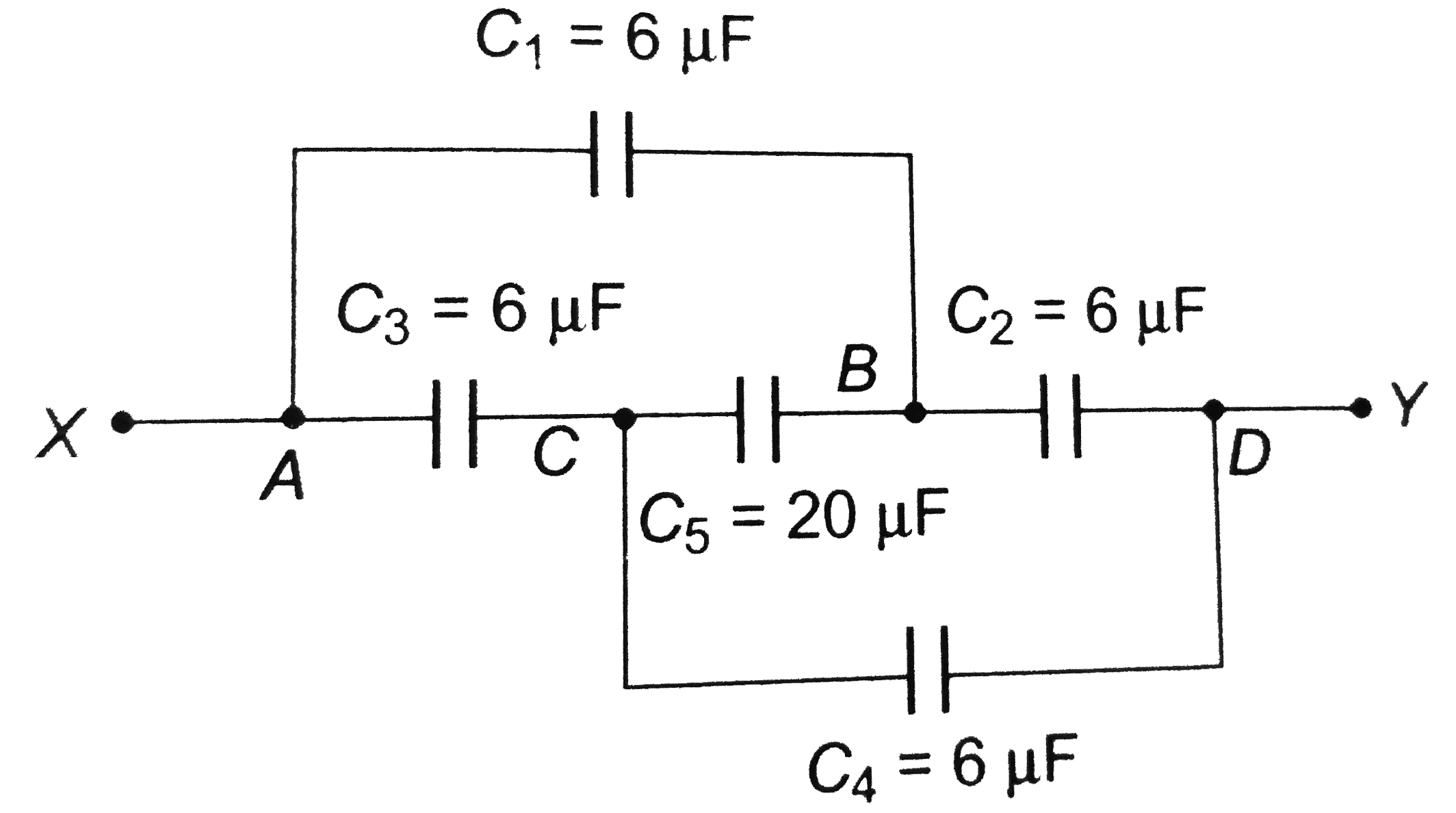
View SolutionThe resultant capacitance of given circuit is
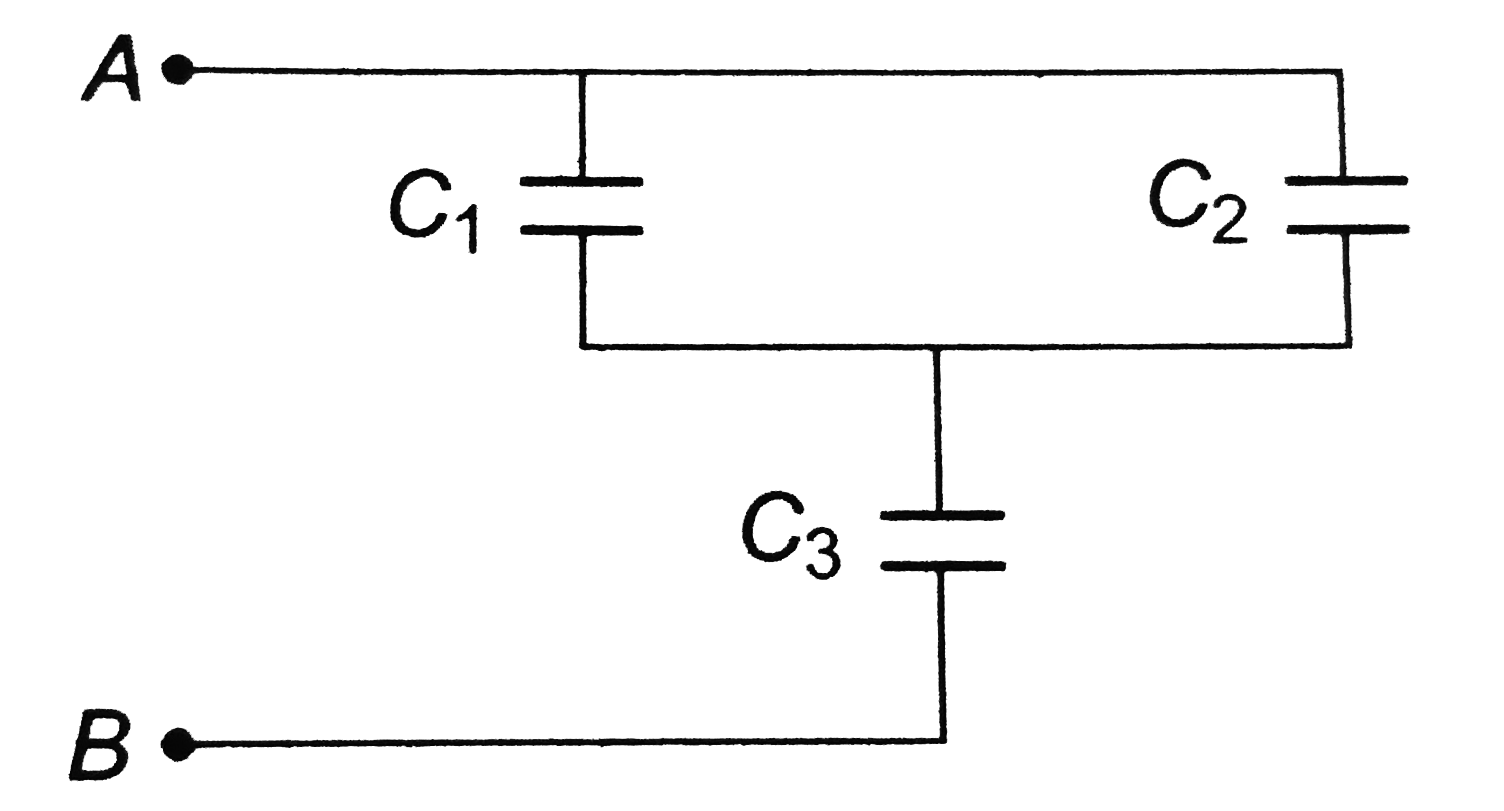
View SolutionIn the given network capacitance, `C_(1) = 10muF, C_(2) = 5 muF` and `C_(3) = 4muF`. What is the resultant capacitance between `A` and `B`?
View SolutionThe equivalent capacitance between `A` and `B` is

View SolutionThe capacitance between the points `A` and `B` in the given circuit will be
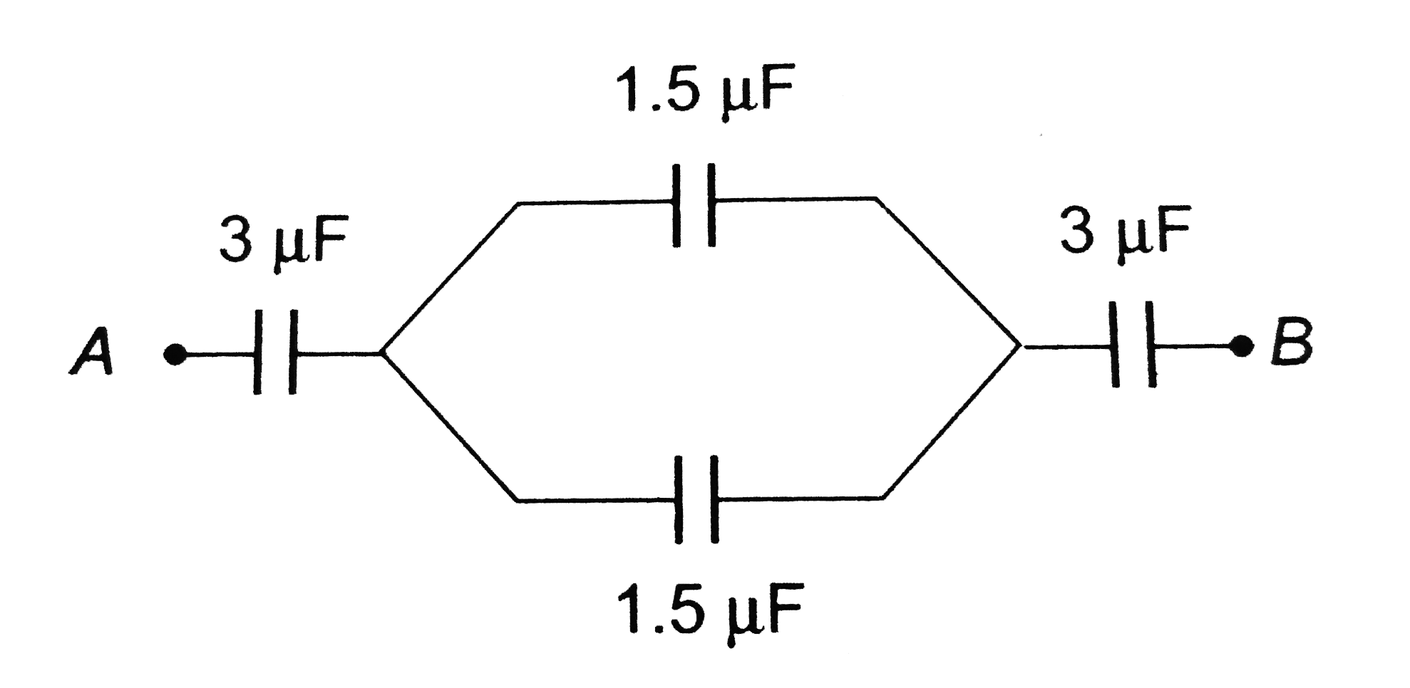
View SolutionIn the circuit shown in figure, each capacitor has a capacity of `3 muF`. The equivalent capacity between `A` and `B` is
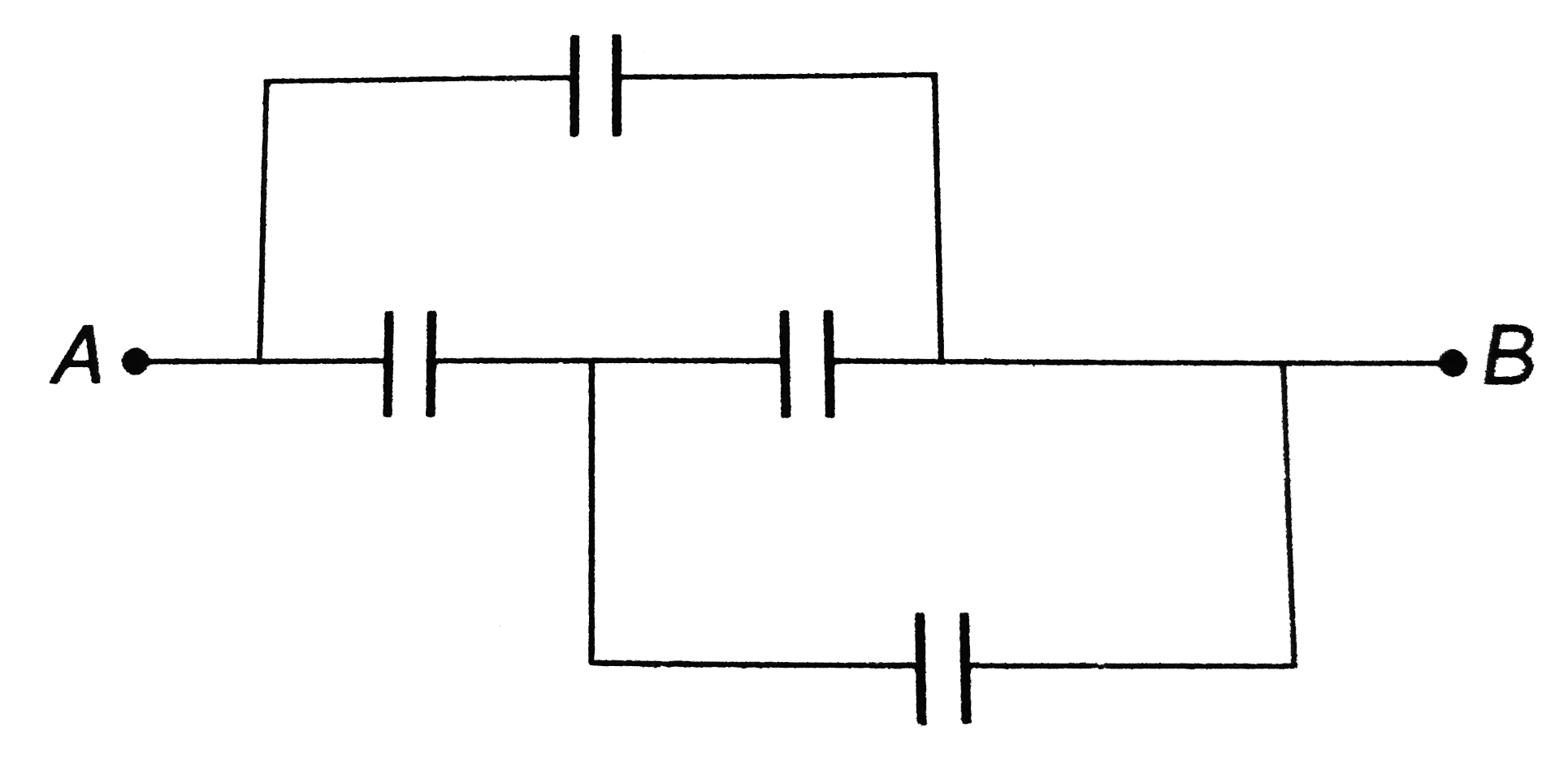
View SolutionWhat is the effective capacitance between `A` and `B` in the following figure ?
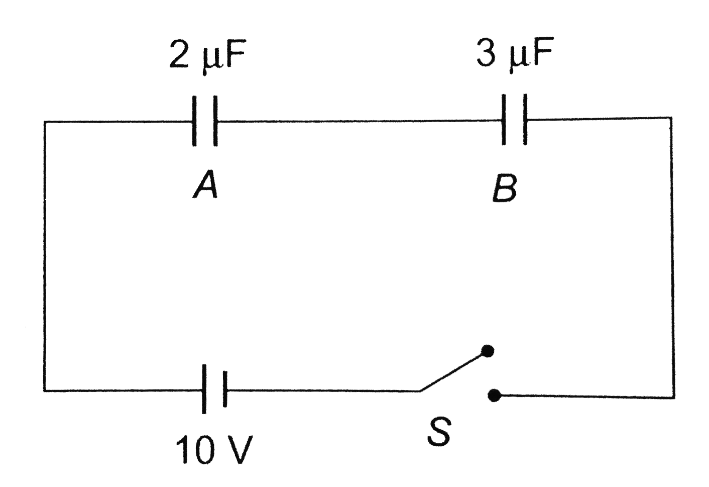
View SolutionTwo capacitors `A` and `B` are connected in series with a battery as shown in the figure. When the switch `S` is closed and the two capacitors get charged fully, then
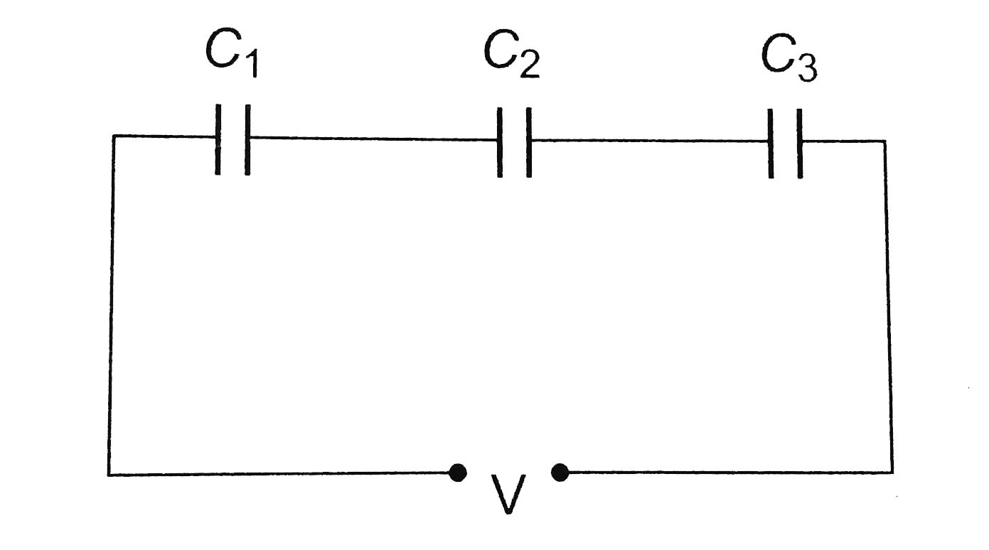
View SolutionIn the figure, three capacitors each of capacitance `6 pF` are connected in series. The total capacitance of the combination will be
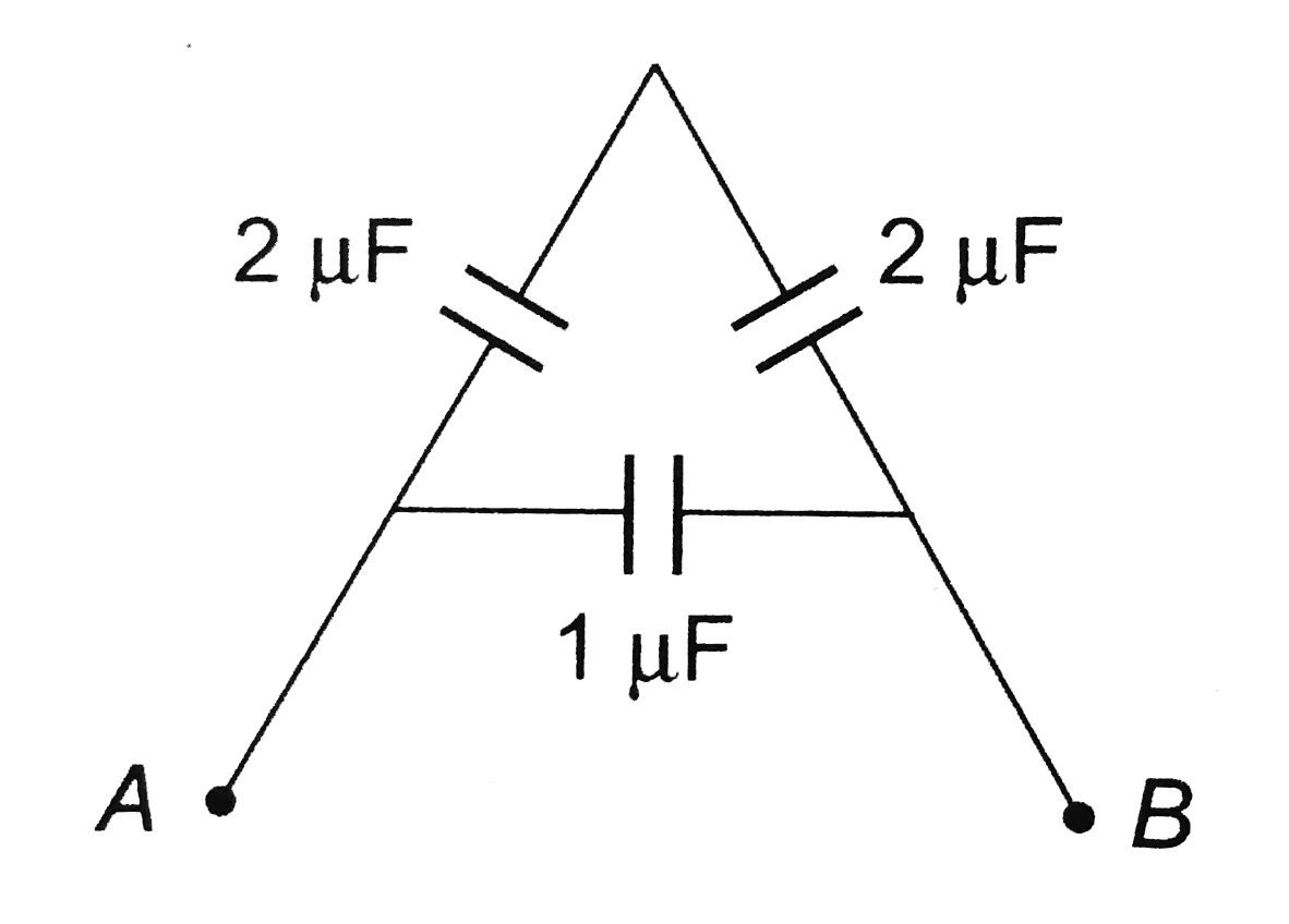
View SolutionEquivalent capacitance between `A` and `B` is
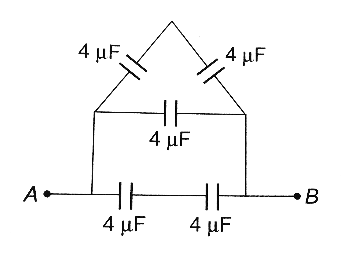
View SolutionTwo capacitors `C_(1) = 2 muF` and `C_(2) = 6 muF` in series, are connected in parallel to a third capacitor `C_(3) = 4 muF`. This arrangement is then connected to a battery of e.m.f `= 2V`, as shown in the figure. How much energy is lost by the battery in charging the capacitors
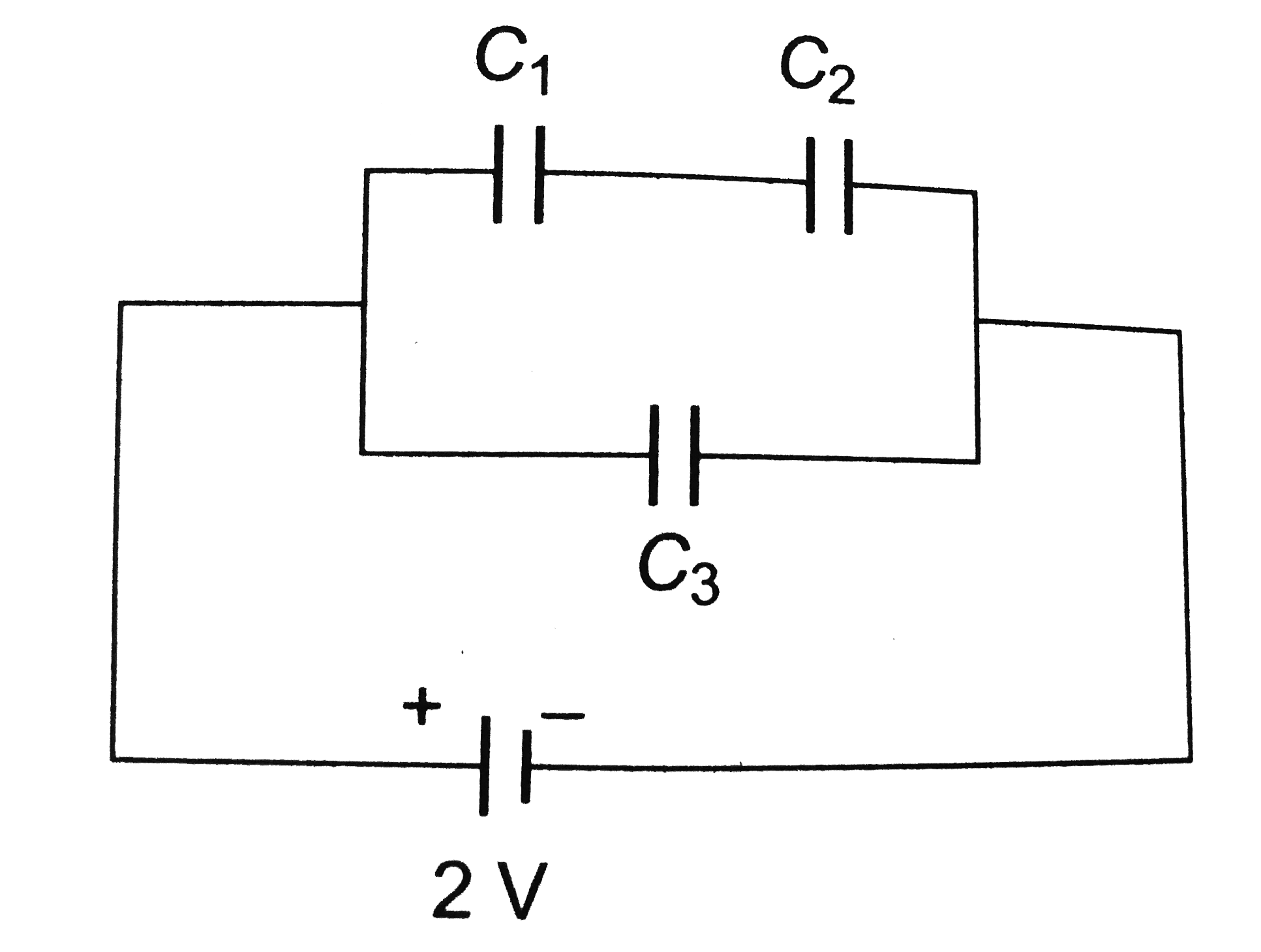
View SolutionThe equivalent capacitance in the circuit between `A` and `B` will be
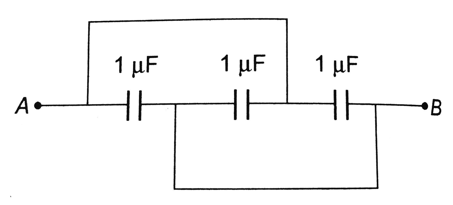
View SolutionThe equivalent capacitance between `A` and `B` is
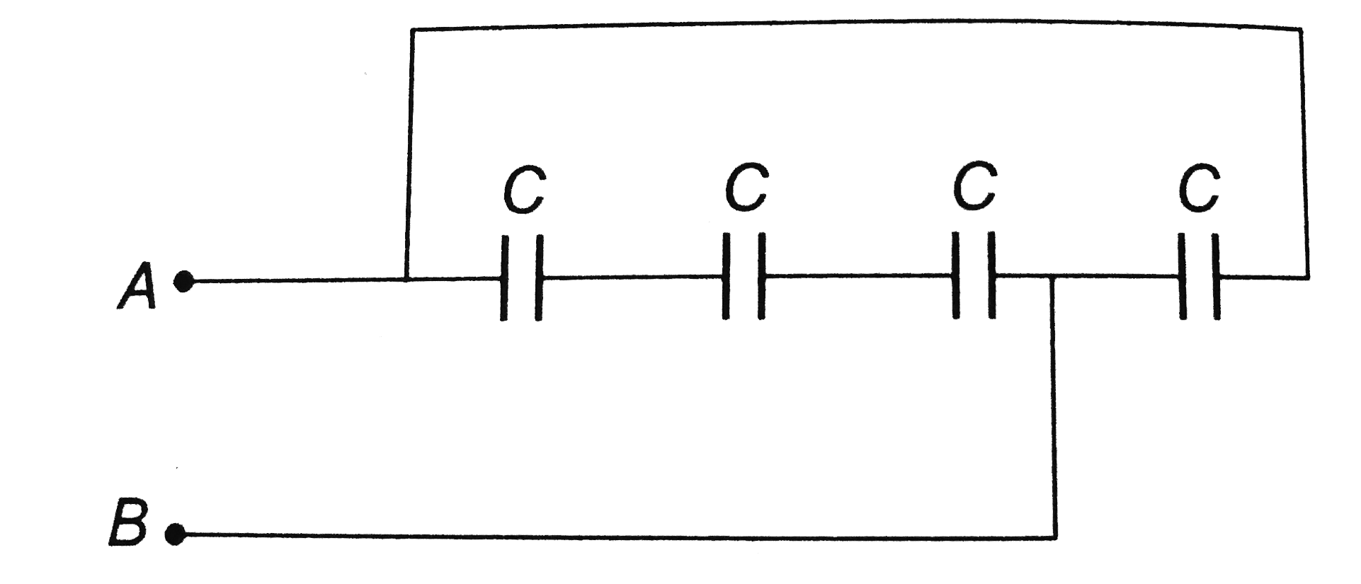
View SolutionThe effective capacitance between `A` and `B` in the figure given is
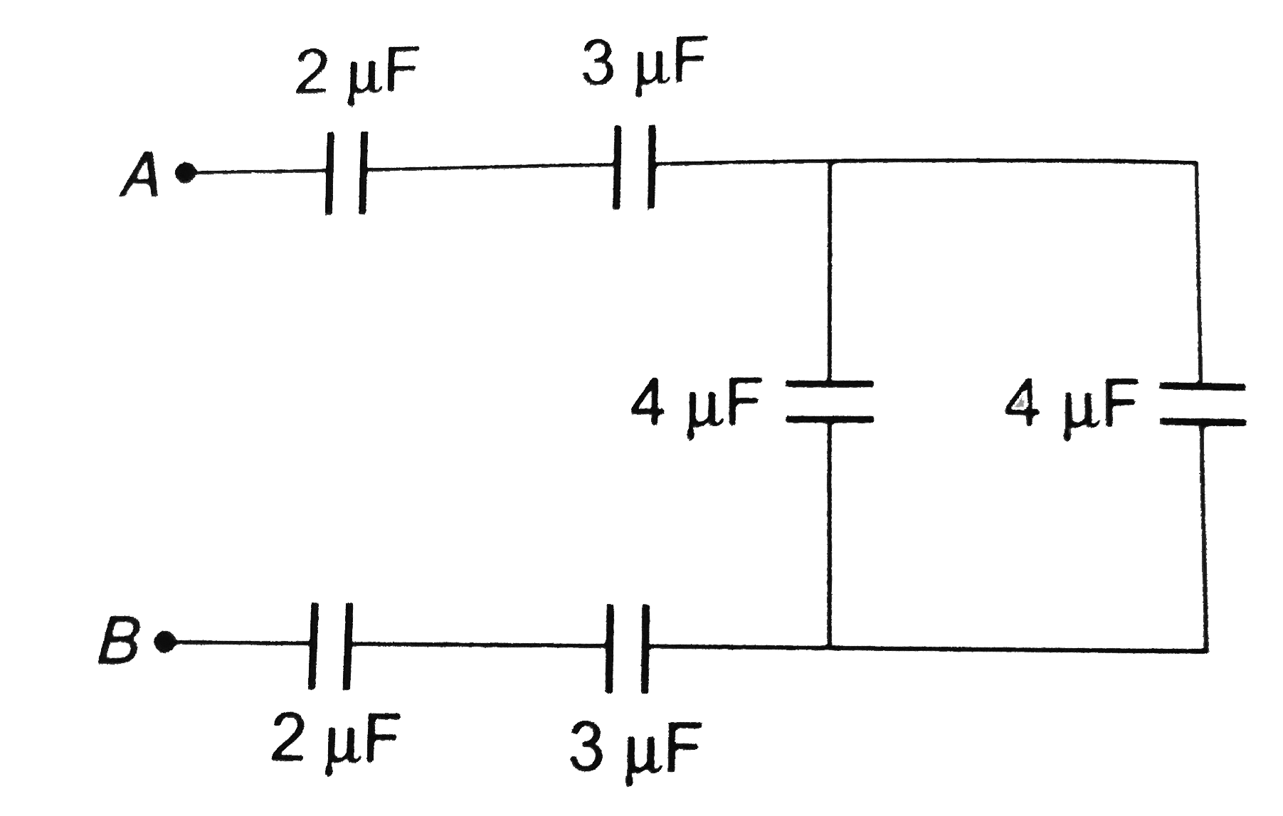
View SolutionThe charge on any of the `2 muF` capacitors and `1 muF` capacitor will be given respectively (in `muC`) as
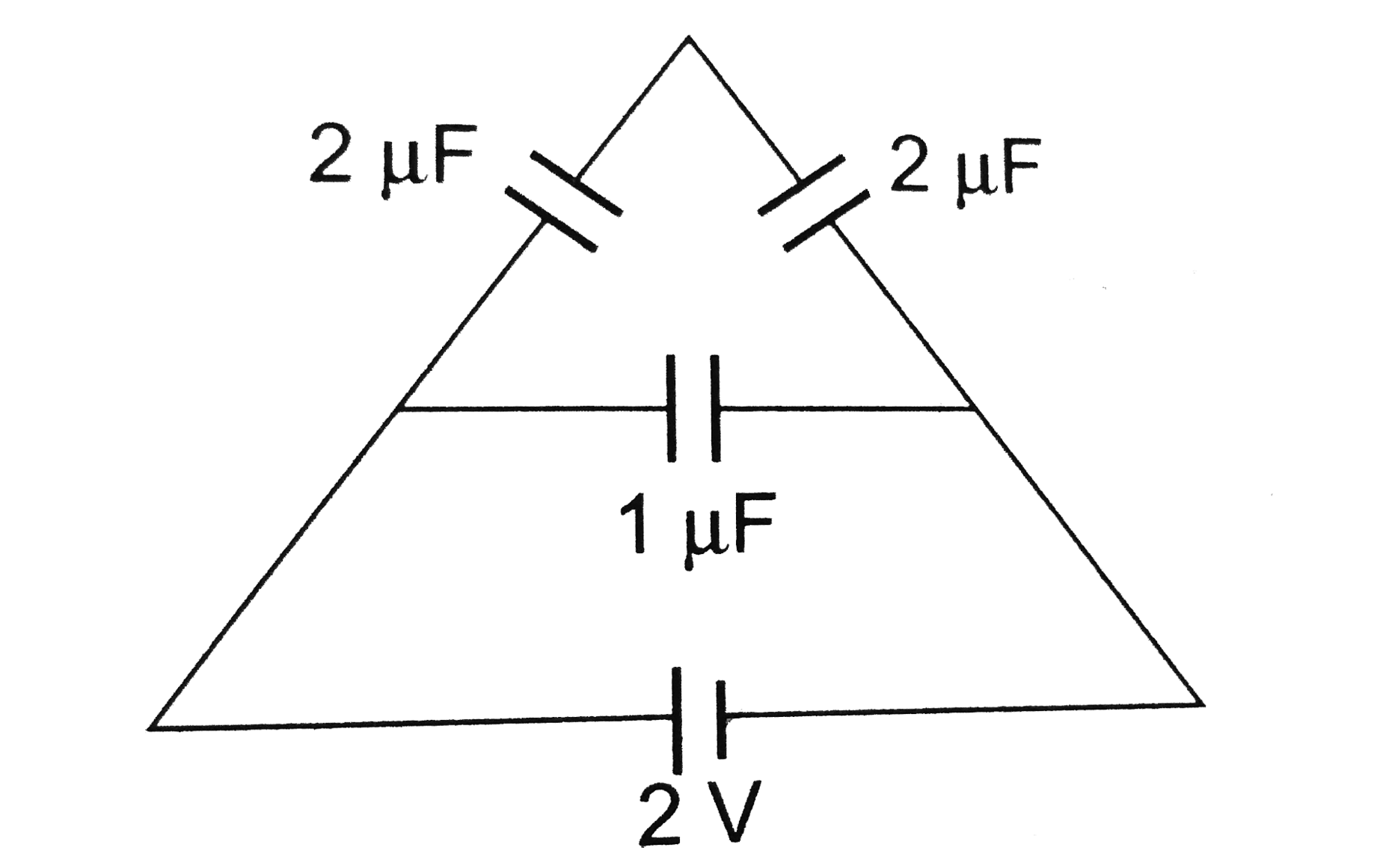
View SolutionIn the circuit as shown in the figure the effective capacitance between `A` and `B` is
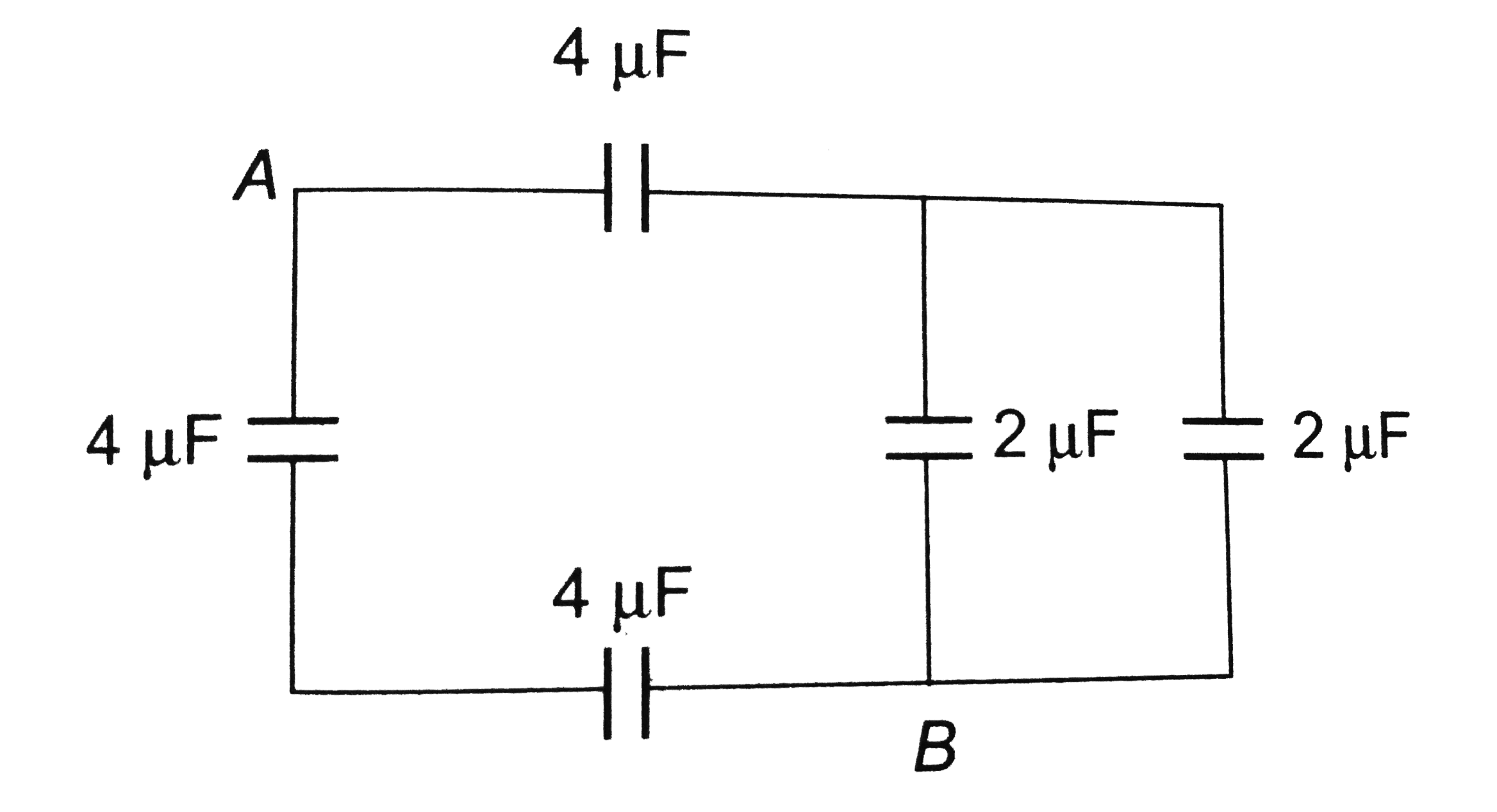
View SolutionFour equal capacitors, each of capacity `C`, are arranged as shown. The effective capacitance between `A` and `B` is
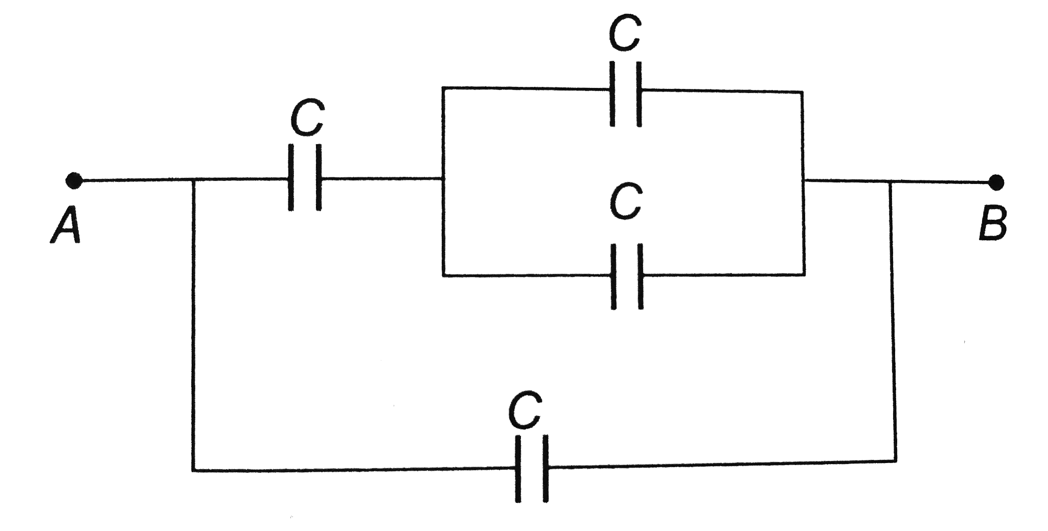
View SolutionIn the figure shown, the effective capacitance between the points `A` and `B`, if each has capacitance `C`, is
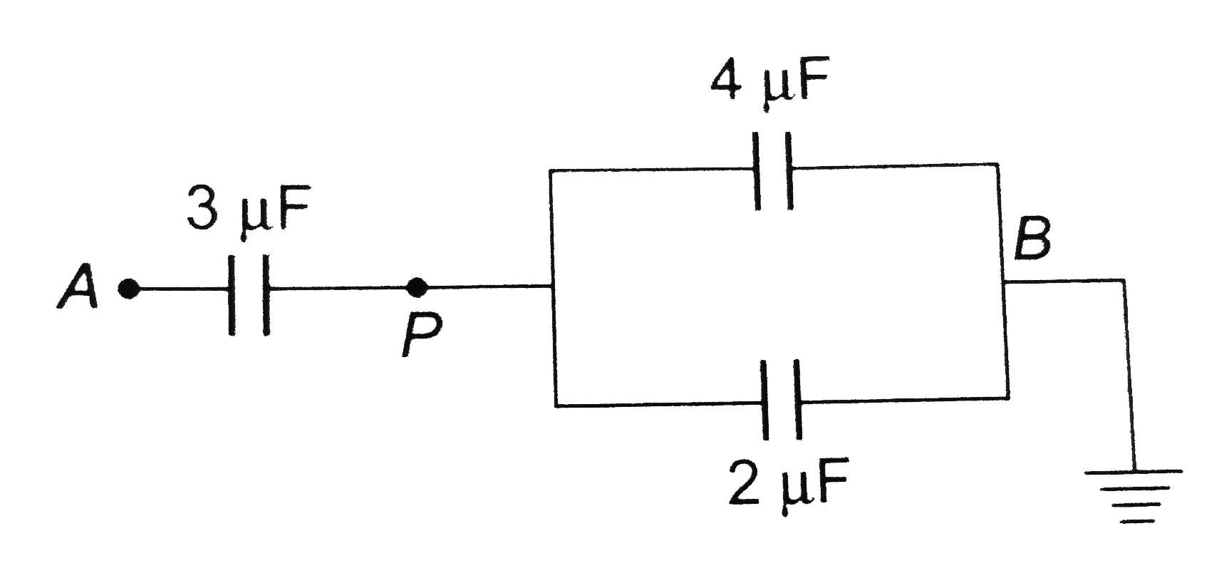
View SolutionIn the figure a potential of `+ 1200 V` is given to point `A` and point `B` is earthed, what is the potential at the point `P` ?
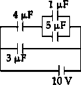
View SolutionIn the given circuit, the charge on `4 mu F` capacitor will be :
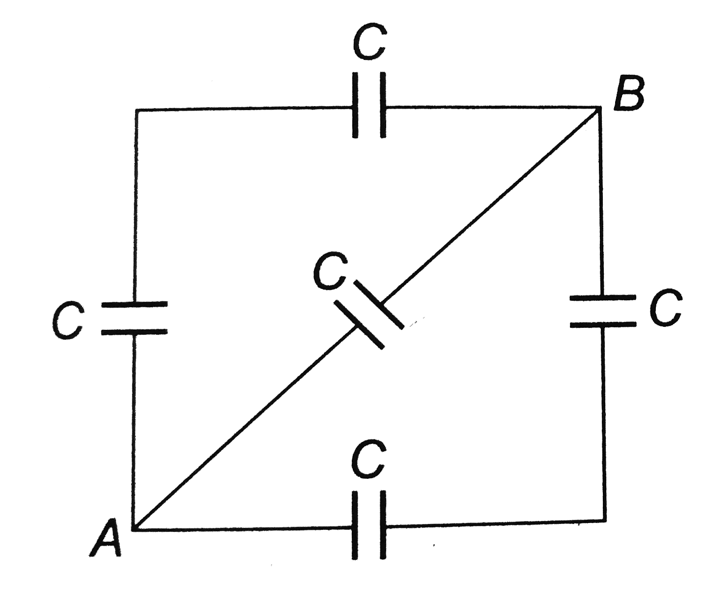
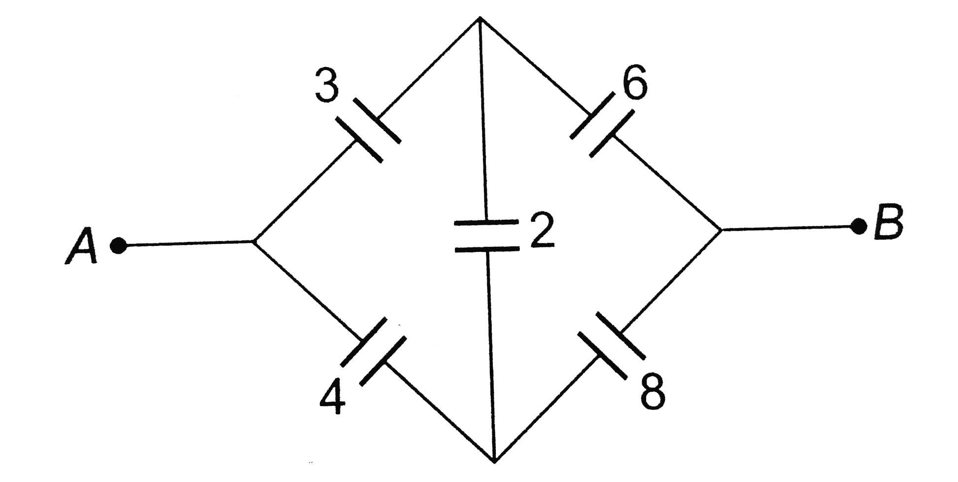
View SolutionEffective capacitance between `A` and `B` in the figure shown is (all capacitance are in `muF`)
View SolutionFour identical capacitors are connected as shown in diagram. When a battery of `6 V` is connected between `A` and `B`, the charges stored is found to be `1.5 muC`. The value of `C_(1)` is
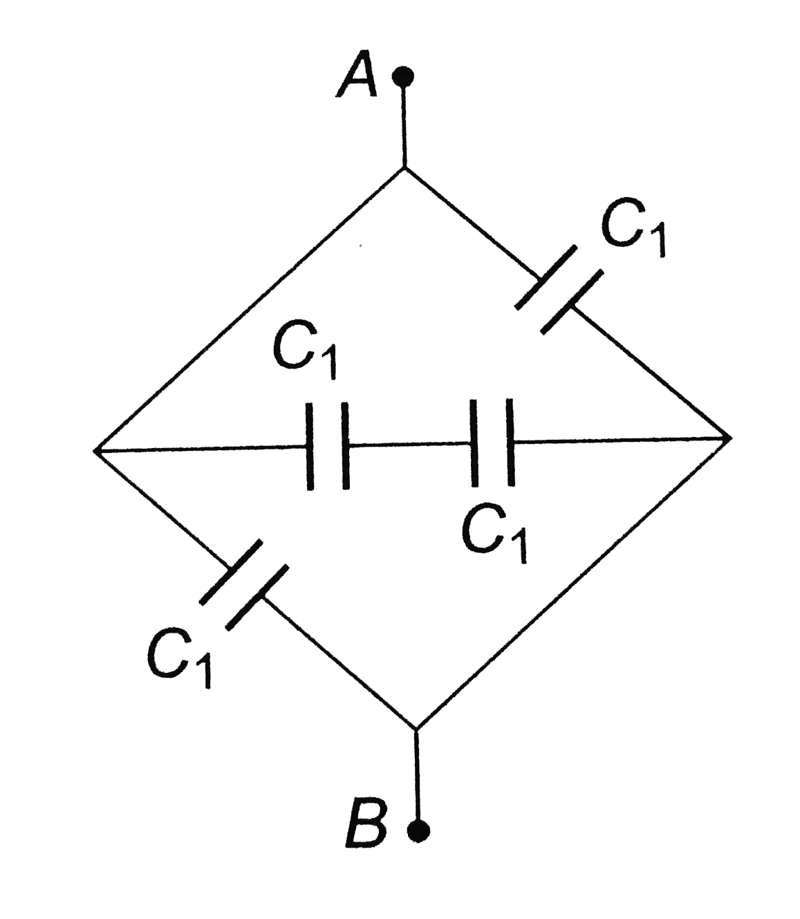
View Solution
Capacitor Circuits questions and complete solutions for chapter ELECTRIC POTENTIAL & CAPACITANCE of A2Z PHYSICS (HINGLISH) of Class 12
All Exercises from A2Z Class 12 PHYSICS ELECTRIC POTENTIAL & CAPACITANCE
- AIIMS Questions
- AIPMTNEET Questions
- Assertion Reason
- Capacitor
- Capacitor Circuits
- Capacitor With Dielectric
- Electric Potential
- Electric Potential Energy
- Euipotentials
- Grouping Of Capacitors
- Problems Based On Mixed Concepts
- Relation Between Electric Field And Potential
- Section B - Assertion Reasoning
- Section D - Chapter End Test