Complete Solutions to Illustration of chapter ELECTRICAL MEASURING INSTRUMENTS of Class 12 book with complete answers and questions
| Class 12 | PHYSICS |
| Chapter | ELECTRICAL MEASURING INSTRUMENTS |
| CENGAGE PHYSICS | Illustration |
| Number Of Questions | 15 |
| Academic Year | 2023-24 |
A galvenometer has a resistance of `50 Omega` and its full-scale deflection current is `50 mu A`. What resistance should be added to it so that it can have a range of `0-5 V`?
View SolutionWhat is the value of the shunt that passes `10%` of the main current through a galvenomenter of `99 Omega`?
View Solutionthe deflection in a moving coil galvenometre falls from `50` divisions to `10` divisions when a shunt of `12 Omega` is applied. What is the resistance of the galvenometre? Assume the main current to remain same.
View SolutionConsider a circular as shows in Fig. `6.5` (a). We want to measure the current `i` flowing in the circuit.
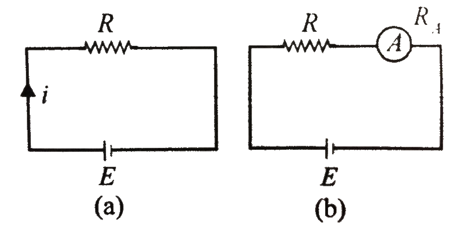
For this we connect an ammeter of resistance `R_(A)` as shows in Fig. `6.5`(b). Find the percentage error in the current.
View SolutionA galvenometer has a resistance of `50 Omega` and its full-scale deflection current is `50 mu A`. What resistance should be added to it so that it can have a range of `0-5 V`?
View SolutionA galvenometer has a resistance of `30 Omega`, and a current of `2 mA` is needed for a full- scale deflection. What is the resistance and how is it to be connected to converted to the voltmeter of `0-2 V` range?
View SolutionTha scale of a galvanometer is divided into `150` equal divisions.The galvanometer has a current sensitivity of 10 divisions per mA and a voltage sensitivity of 2 divisions per mV . The galvanometer be designed to read (i) `6` A per division and (ii) `1 V` per division?
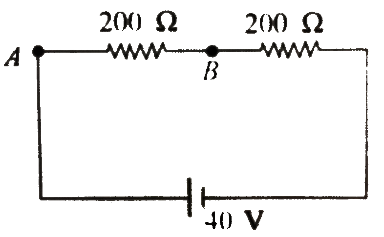
View Solution(i) In fig. `6.7`, find the potential difference berween the points `A` and `B`.
(ii) Now we wish to measure this potential difference by using a voltemter of resistance `2 k Omega`. Find the reading of the voltumeter and percentage error.
(ii) Solve part (ii) if the voltumter were of resistance `20 k Omega`. What conculsion do you draw from the results you get in the above parts?
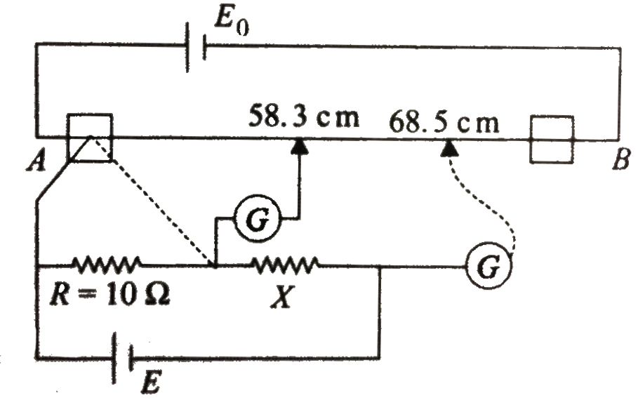
View SolutionFigure `6.12` shows a potentiometer circular for comparison of two resistances. The balance point with a standard resistor `R = 10.0 Omeag ` is found to be `58.3 cm`, while that with the unknows resistance `X` is `68.5 cm`. Determine the value of `X`. What would you do if you fail to find a balance point with the given cell `E`?
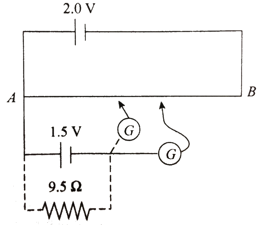
View SolutionFigure `6.13` shows a `2.0 V` potentiometer used for the determination of internal resistance of a `1.5 V` cell. The balance point of the cell in open circuit is `76.3 cm`. Whan a resistor of `9.5 Omega` is used in the external circuit of the cell, the balance point shifts to `64.8 cm`, length of the potentiometer. Dentermine the internal resistance of the cell.
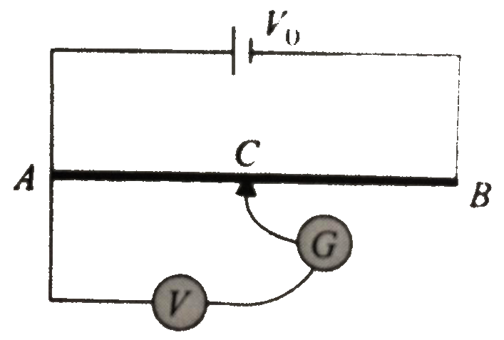
View SolutionA voltage `V_(0)` is applied to a potentiometer whose sliding constant is exacly in tne middle. A voltmeter `V` is connected between the sliding constant and one fixed end of the potentionmeter. If is assumed that the resistance of the voltmeter is not very high in comparison to the resistance of the potentiometer wire. What voltage will the voltmeter show : higher than, less than, or equal to `V_(0)//2`?
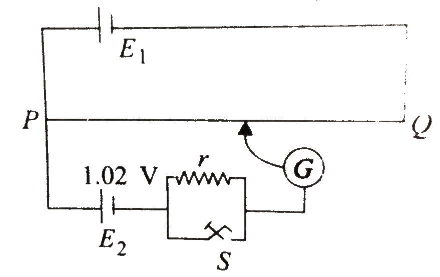
View SolutionPotentiometer wire `PQ` of `1 m` length is connected to a standard cell `E_(1)`. Another cell `E_(2)` of emf `1.02 V` is connected with a resistance `r` and a switch `S` as shown in the circuit diagram. With switch `S` open, the null position is obtained at a distance of `51 cm` from `P`.
(i) Calculate the potential gradient of the potentiometer wire.
(ii) Find the emf of cell `E_(1)`.
(iii) When switch `S` is closed, will the null point move toward `P` or toward `Q`? Give reason for your answer.
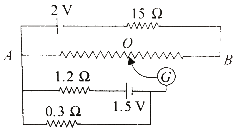
View SolutionIn Fig. `6.16`, `AB` is a `1 m` long uniform wire of `10 Omega` resistance. Other data are shows in the figure. Calculate (i) potential gradient along `AB` and (ii) length of AO when galvanometer shows no deflection.
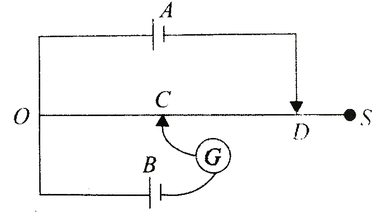
View SolutionCells `A` and `B` and a galvanometer `G` are connected to a side wire `OS` by two sliding contacts `C` and `D` as shows in Fig. `6.17`. The slide wire is `100 cm` long and has a resistance of `12 Omega`. With `OD = 75 cm`, the galvanometer gives no deflections when `OC` is `50 cm`. If `D` is moved to touch the end of wire `S`, the value of `OC` for which the galvanometer shows no deflection is `62.5 cm`. The emf of cell `B` is `1.0 V`. Calculate
(i) the potential difference across `O` and `D` when `D` is at `75 cm` mark from `O`
(ii) the potential difference across `OS` when `D` touches `S`
(iii) internal resistance of cell `A`
(iv) the emf of cell `A`
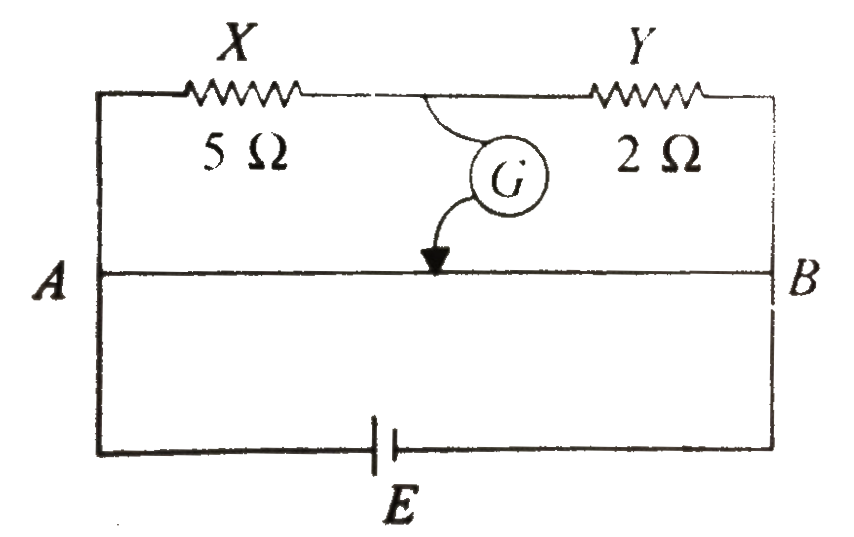
View SolutionIn the simple potentionmeter circuit, where the length `AB` of the potentiometer wire is `1 m`, the resistors `X` and `Y` have values of `5 Omega` and `2 Omega`, respectively. When `X` is shunted by a wire, the balance point is found to be `0.625 m` from `A`. What is the resistance of the shunt?
View Solution
Illustration questions and complete solutions for chapter ELECTRICAL MEASURING INSTRUMENTS of CENGAGE PHYSICS (ENGLISH) of Class 12