Complete Solutions to Single Correct of chapter ELECTRICAL MEASURING INSTRUMENTS of Class 12 book with complete answers and questions
| Class 12 | PHYSICS |
| Chapter | ELECTRICAL MEASURING INSTRUMENTS |
| CENGAGE PHYSICS | Single Correct |
| Number Of Questions | 94 |
| Academic Year | 2023-24 |
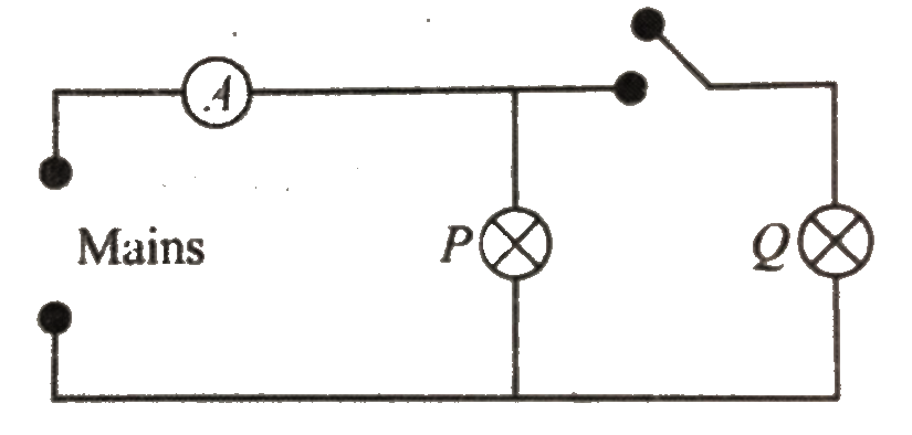
How will the reading in the ammeter `A` of Fig. 6.39 be affected if another identical bulb `Q` is connected in parallel to `P` as shows. The voltage in the mains is maintained at a constant value.
View SolutionA potentiometer is connected across `A `and `B` and a balance is obtained at `64.0 cm`. When the potentiometer lead at `B` is moved to `C`, a balance is found at `8.0 cm`. If the potentiometer is now connected across `B` and `C`, a balanced will be found at

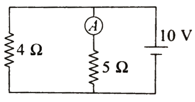
View SolutionIn the circuit shows in Fig. `6.41`, the reading of the ammeter is (assume internal resistance of the battery be to zero)
View SolutionIn the circuit shows in Fig. `6.42`, resistors `X` and `Y`, each with resistance `R`, are connected to a `6 V` battery of negligible internal resistance. A voltmeter, also of resistance `R`, is connected across `Y`.
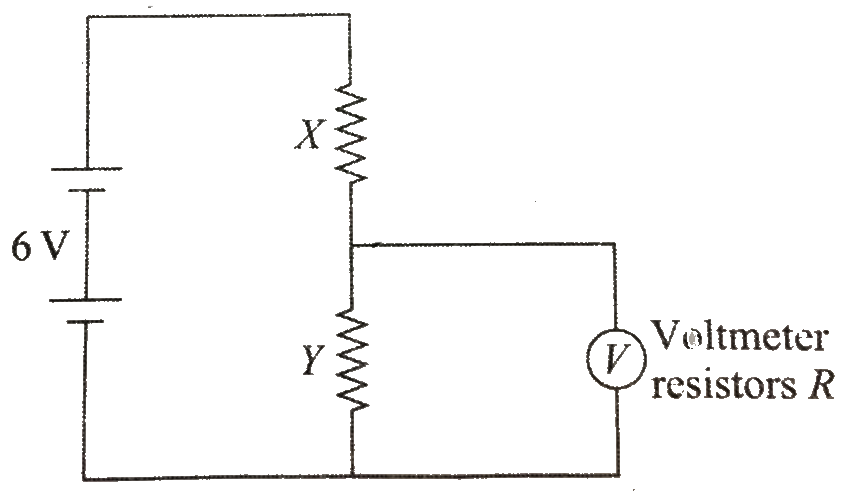
What is the reading of the voltmeter?
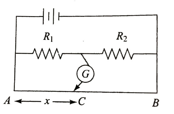
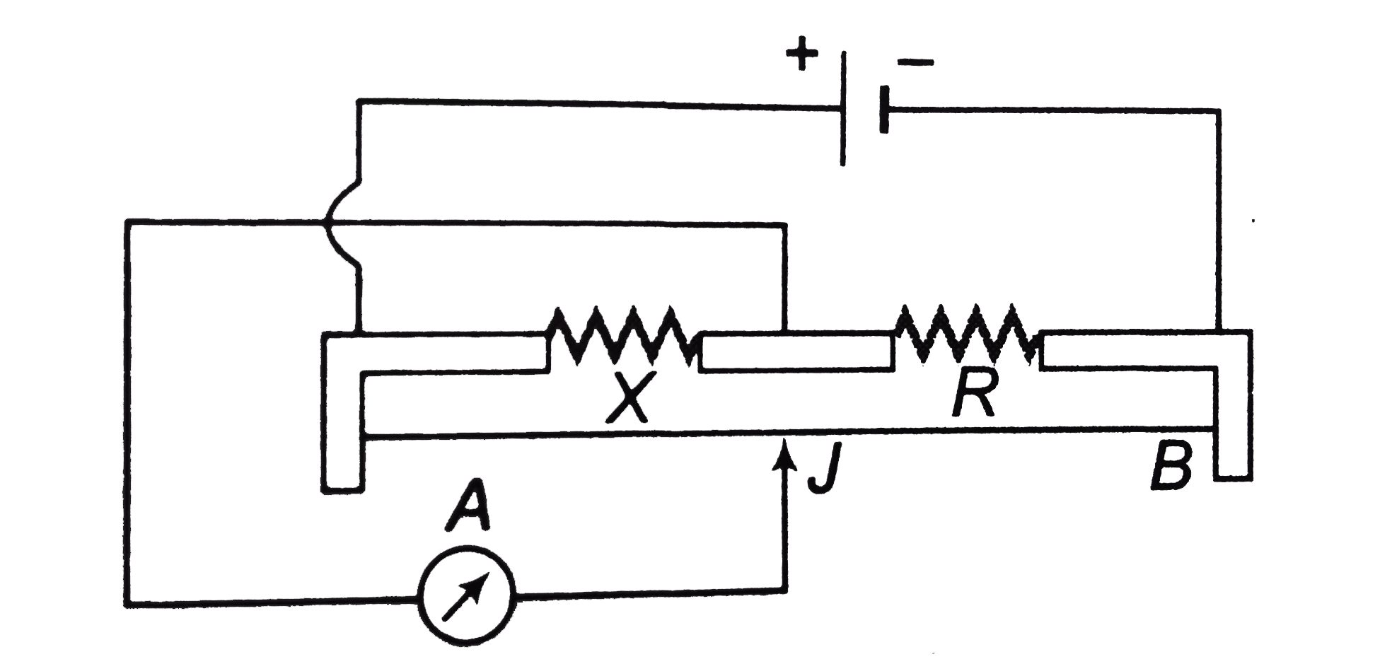
View SolutionIn the shows arrangement of a meter bridge, if `AC` corresponding to null deflection of galvanometer is x, what would be its value if the radius of the wire `AB` is doubled?
View SolutionThe length of a wire of a potentiometer is 100 cm, and the emf of its cell is E volt. It is employed to measure the emf of a battery whose internal resistance is `0.5Omega`. If the balance point is obtained at l = 30 cm from the positive end, the emf of the battery is
View SolutionIn a meter bridge experiment, null point is obtained at `20 cm` from one end of the wire when resistance `X` is balanced against another resistance `Y`. If `X lt Y`, then the new position of the null point from the same end, if one decides to balance a resistance of `4 X` against `Y` will be at.
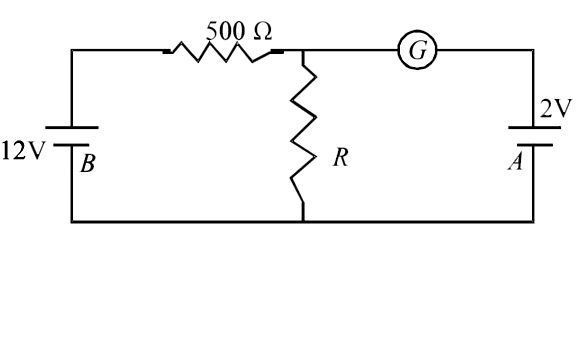
View SolutionIn the circuit, the galvanometer G shows zero deflection. If the batteries A and b have negligible internal resistance, the value of the resistor R will be -
View SolutionIn a potentiometer experiment, the balancing with a cell is at length 240 cm. On shunting the cell with a resistance of `2 Omega`, the balancing becomes 120 cm. The internal resistance of the cell is
View SolutionIf in the experiment of Wheatstone's bridge, the positions of cells and galvanometer are interchanged, then balance point will
View SolutionSensitivity of potentiometer can be increased by
View SolutionThe resistance of a galvanometer is `10 Omega`. It gives full-scale deflections when `1 mA` current is passed. The resistance connected in series for converting it into a voltmeter of `2.5 V` will be
View SolutionA milliammeter of range `10 mA` has a coli of resistance `1 Omega`. To use it as an ammeter of range `1 A`, the required shunt must have a resistance of
View SolutionTwo cells of emfs `E_(1)` and `E_(2)(E_(1)gtE_(2))` are connected as shown in figure.

When a potentiometer is connected between A and B, the balancing length of the potentiometer wire is 300 cm. On connection the same potentiometer between A and C, the balancing length is 100 cm. The ratio `(E_(1))/(E_(2))` is
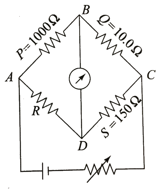
View SolutionFigure `6.46`, shows a wheatstone net, with `P = 1000 Omega`,`Q = 10.0 Omega`,`R`(unknows), `S` variable and near `150 Omeag` for balance. If the connections across `A,C` and `B,D` are interchanged, the error range in `R determination would
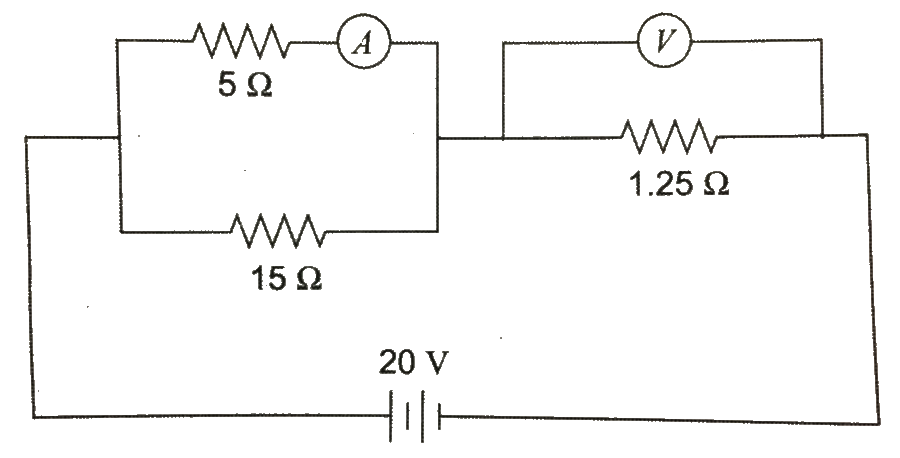
View SolutionAn ideal ammeter (zero resistance) and an ideal voltmeter (infinite resistance) are connect as shows in Fig. `6.47`. The ammeter and the voltmeter readings are
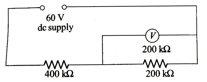
View SolutionA constant `60 V` dc supply is connected across two resistors of resistance `400 k Omega` and `200 k Omega`. What is the reading of the voltmeter, also of resistance `200 k Omega`, when connected across the second resistor as shows in Fig. `6.48`?
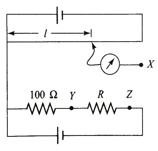
View SolutionFigure `6.49` shows a circuit that may be used to compare the resistance `R` of an unknown resistor with a `100 Omega` standard. The distance `l` from one end of the potentiometer slider wire to the balance point are `400 mm` and `588 mm` when `X` is connected to `Y` and `Z`, respectively. The length of the slide wire is `1.00 m`. What is the value of resistance `R`?
View SolutionIn the circuit shown in Fig. `6.50`, an idel ammeter and an ideal voltmeter are used. Whan the key is open, the voltmeter reads `1.53 V`. When the key is closed, the ammeter reads `1.0 A` and the voltmeter reads `1.03 V`. The resistance `R` is

View SolutionIn which of the follwing arrangements of resistors does the meter `M`, which has a resistance of `2 Omega`, give the largest reading when the same potential difference is appliced between points `P` and `Q`?
View SolutionFigure `6.51` shows a simple a potentiometer circuit for measuring a small emf produced by a thermocouple.
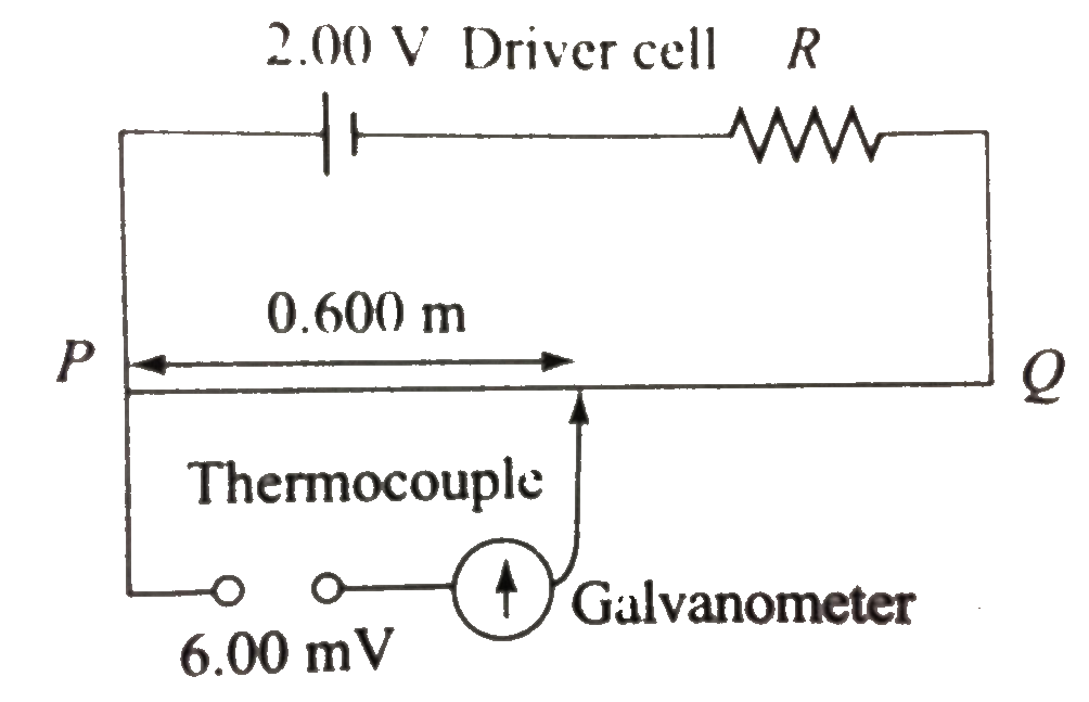
The meter wire `PQ` has a resistance of `5 Omega`, and the driver cell has an emf of `2.00 V`. If a balance point is obtained `0.600 m` along `PQ` when measuring an emf of `6.00 mV`,
what is the value of resistance `R`?
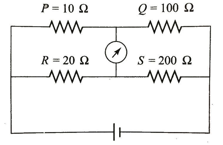
View SolutionFigure`6.52` shows a balanced wheatstone net. Now, it is disturbed by changing `P` to `11 Omega`. Which of the following steps will not bring the bridge to balance again?
View SolutionIn an experiment to measure the internal resistance of a cell by a potentiometer, it is found that the balance point is at a length of `2 m` when the cell is shunted by a `5 Omega` resistance and is at a length of `3 m` when the cell is shunted by a `10 Omega` resistance, the internal resistance of the cell is then
View SolutionWhen an ammeter of negligible internal resistance is inserted in series with circuit, it reads `1 A`. When a voltmeter of very large resistance is connected across `R_(1)`, it reads `3 V`. But when the points `A` and `B` are short-circuited by a conducting wire, then the voltmetre measures `10.5 V` across the battery. The internal resistance of the battery is equal to
View SolutionAn `80 Omega` galvanometer deflects full-scale for a potential of `20 mV`. A voltmeter deflcting full-scale of `5 V` is to be made using this galvanometer. We must connect
View SolutionA voltmeter having a resistance of `1800 Omega` employed to measure the potential difference across a `200 Omega` resistor which is connected to the terminals of a dc power supply having an emf of 50 V and an internal resistance of `20 Omega`. What is the percentage decrease in the potential difference across the `200 Omega` resistor as a result of connecting the voltmeter across it?
View SolutionIn the given circuit, the voltmeter and the electric cell are ideal. Find the reading of the voltmetre

View SolutionThe emf of the driver cell of a potentiometer is `2 V`, and its internal resistance is negligible. The length of the potentiometer wire is `100 cm`, and resistance is `5 ohm`. How much resistance is to be connected in series with the potentiometer wire to have a potential gradient of `0.05 m V cm^(-1)`?
View SolutionIn the above question, if the balancing length for a cell of emf `E` is `60 cm`, the value of `E` will be
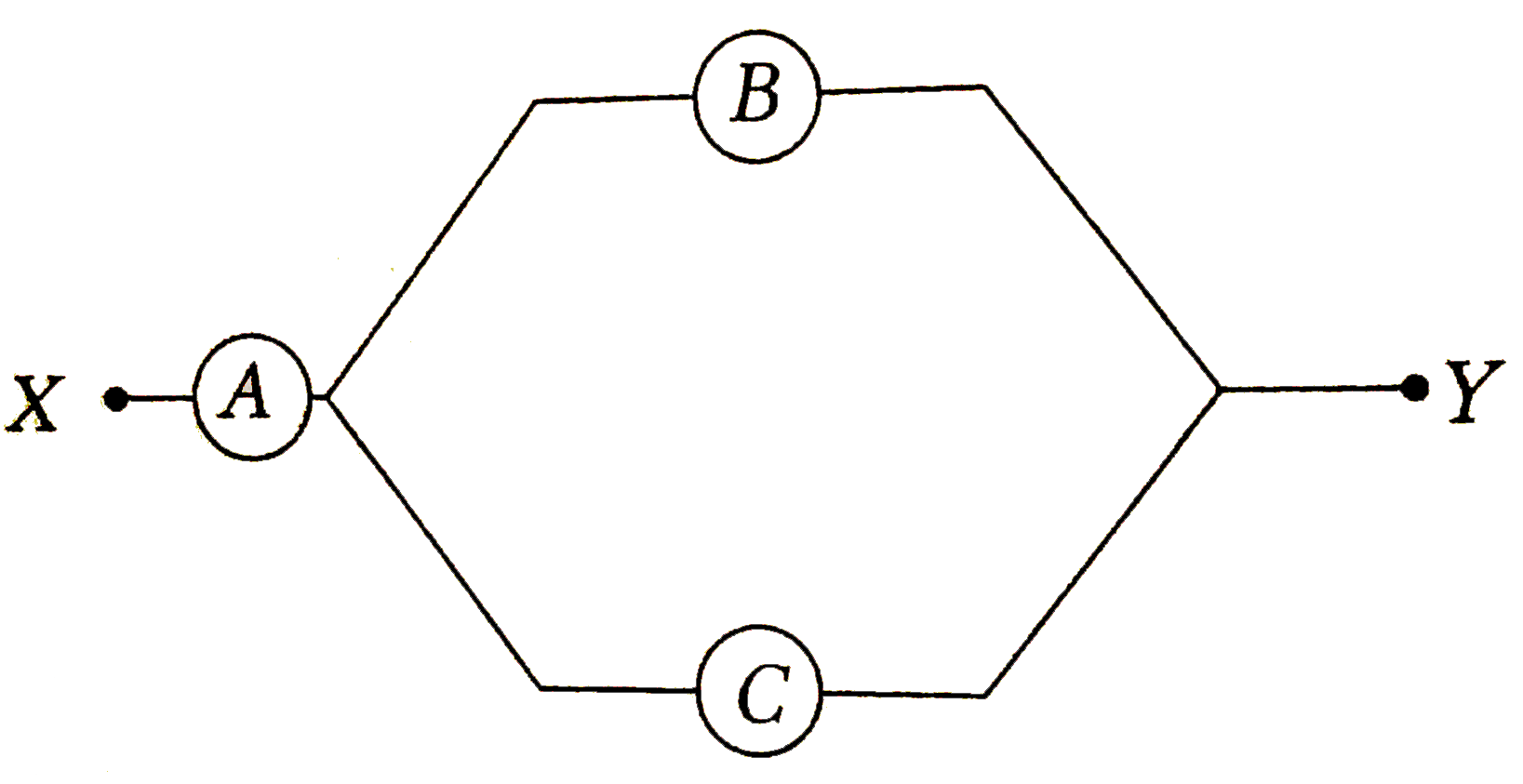
View SolutionThree voltmeters A, B and C having resistances R, `1.5R` and 3R respectively, are used in a circuit as shown. When a potential difference is applied between X and Y, the readings of the voltmeters are `V_(1), V_(2)` and `V_(3)` respectively. Then,
View SolutionA milliammeter of range `10 mA` and resistance `9 Omega` is joned in a circuit as shown. The meter gives full scale deflection for current `I `when A and B are used as its terminals,i.e.,current enters at A and leaves at B (C is left isolated). The value of I is
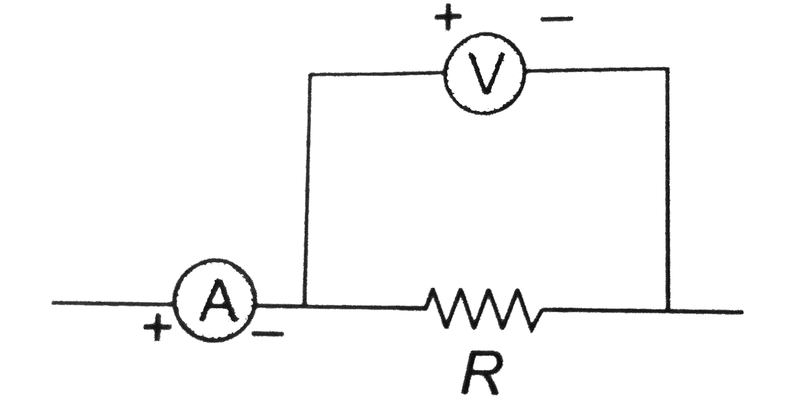
View SolutionA candidate connects a moving coil voltmeter `V`, a moving coil ammeter `A` and a resistance `R` as shown in figure. If the voltmeter reads `24 V` and the ammeter reads `4 A`, R is
View SolutionIf a shunt `1//10` of the coil resistance is applied to a moving coil galvanometer, its sensitivity becomes
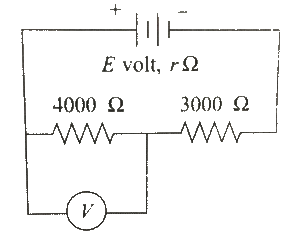
View SolutionIn Fig.`6.59`, when an ideal voltmetre is connected across `4000 Omega` resistance, it reads `30 V`. If the voltmeter is connected across `3000 Omega` resistance, it will read
View SolutionA voltmeter has a resistance `G` and range `V`. Calculate the resistance to be used in series with it to extend its range to `nV`.
View SolutionA galvanometer has a resistance of `3663Omega`. A shunt `S` is connected across it such that (`1//34`) of the total current passes through the galvanometer. Then the value of the shunt is
View SolutionIn `Q.36`, the combined resistance of the shunt and the galvanometer is
View SolutionIn `Q.36`, the external resistance that must be connected is series with the main circuit so that the total current in the main circuit remains unaltered even when the galvanometer is shunted is
View SolutionTwo moving coil galvanometers `1` and `2` are with identical field magnets and suspension torque constants, but with coil of different number of turns `N_(1)` and `N_(2)`, area per turn `A_(1)` and `A_(2)`, and resistance `R_(1)` and `R_(2)`. When they are connected in series in the same circuit, they show deflections `theta_(1)` and `theta_(2)`. then `theta_(1)//theta_(2)` is
View SolutionAn ammetre is obtained by shunting a `30 Omega` galvanometer with a `30 Omega` resistance. What additional shunt should be connected across it to double the range ?
View SolutionThree voltmeters are connected as shown.

A potential difference has been applied between `A` and `B`. On closing the swich `S`, readings of voltmeters?
View SolutionA constant potential difference is applied across a resistance. Consider variation of resistance with temperature. Which graph represents best the variation of power produced in resistance versus resistance?
View SolutionIn Fig.`6.61` the voltmetre and ammeter shows are ideal. Then voltmeter and ammeter readings, respectively, are
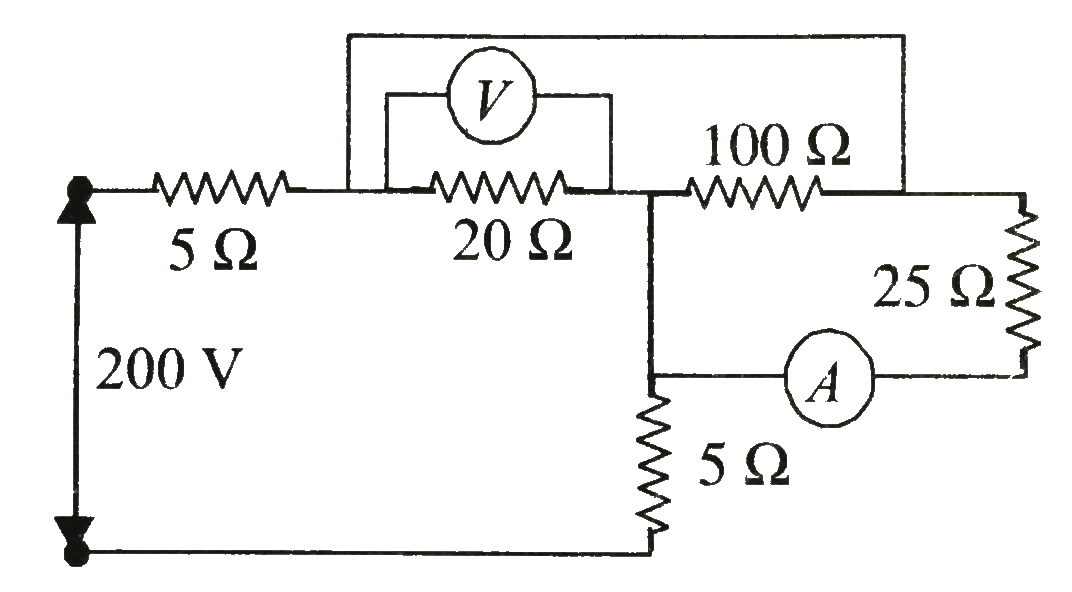
View SolutionA potentiometer arrangement is shows in Fig. `6.62`. The driver cell has emf `e` and internal resistance `r`. The resistance of potentiometer wire `AB` is `R.F` is the cell of emf `e//3` and internal resistance `r//3`. Balance point `(J)` can be obtained for all finite value of
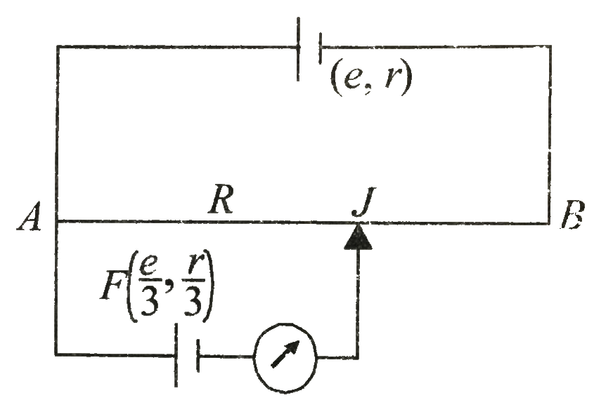
View Solution`50 Omega` and `100 Omega` resistors are connected in series. This connection is connected with a battery of 2.4 volts. When a voltmeter of `100 Omega` resistance is connected across `100 Omega` resistor, then the reading of the voltmeter will be
View SolutionAn ammeter gives full scale deflection when current of 1.0 A is passed in it. To convert it into 10 A range ammeter, the ratio of its resistance and the shunt resistance will be
View Solution100mA current gives a full scale deflection in a galvanometer of `2Omega` resistance. The resistance connected with the galvanometer to convert it into a voltmeter to measure 5V is
View SolutionWhen a `12 Omega` resistor is connected with a moving coil galvanometer, then its deflection reduces form 50 divisions to 10 divisions. The ressitance of the galvanometer is
View SolutionThe resistance of a galvanometer is 90 ohm s. If only 10 percent of the main current may flow through the galvanometer, in which way and of what value, a resistor is to be used
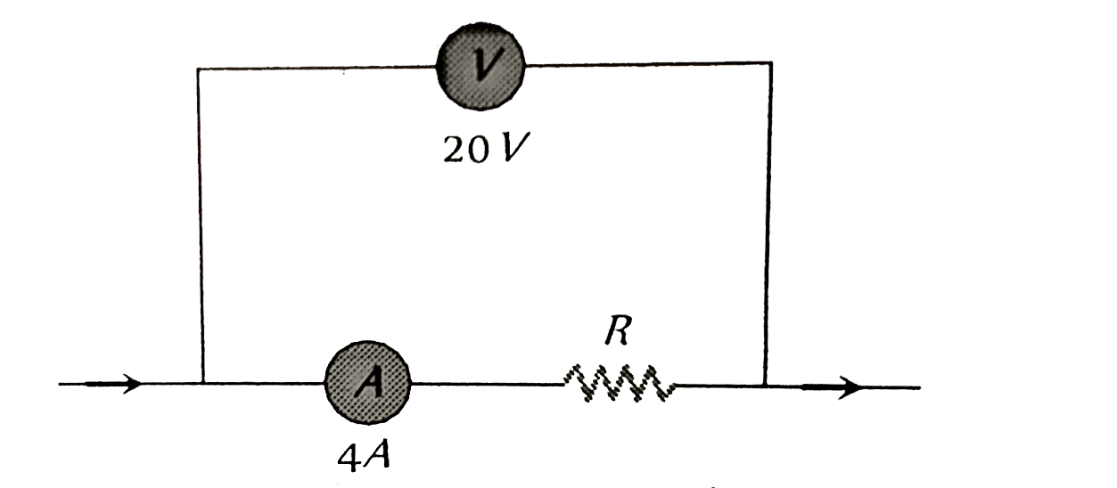
View SolutionIn the diagram shown, the reading of voltmeter is 20 V and that of ammeter is 4 A . The value of R should be (Consider given ammeter and voltmeter are not ideal)
View SolutionA voltmeter of resistance 998 `Omega` is connected across a cell of emf 2 V and internal resistance `2Omega`. The potential difference across the voltmeter is
View SolutionA 100 V voltmeter of internal resistance 20 `kOmega` in series with a high resistance R is connected to a 110 V line. The voltmeter reads 5 V, the value of R is
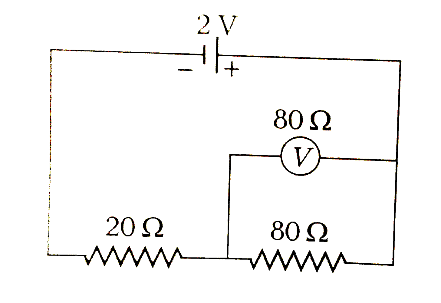
View SolutionIn the following circuit, the emf of the cell is 2 V and the internal resistance is negligible. The resistance of the voltmeter is `80Omega`. The reading of the voltmeter will be
View SolutionA galvanometer has 30 divisions and a sensitivity `16 mu A //"div"`. It can be converted into a voltmeter to read `3 V` by connecting
View SolutionVoltmeters `V_(1)` and `V_(2)` are connected in series across a `D.C.` line `V_(1)` reads 80 volts and has a per volt resistance of `200 ohms`, `V_(2)` has a total resistance of 32 kilo ohms.
The line voltage is
View SolutionA voltmeter has a range `O - V` with a series resistance `R`. With a series resistance `2R`, the range is `O - V'`. The correct relation between `V` and `V'`is
View SolutionA moving coil galvanometer is converted inot an ammeter reading upto `0.03`A by connecting a shunt of resistance 4r across it and into an ammeter reading upto `0.06` A when a shunt of resistance r is connected across it. What is the maximum current which can be sent through this galvanometer, if no shunt is used?
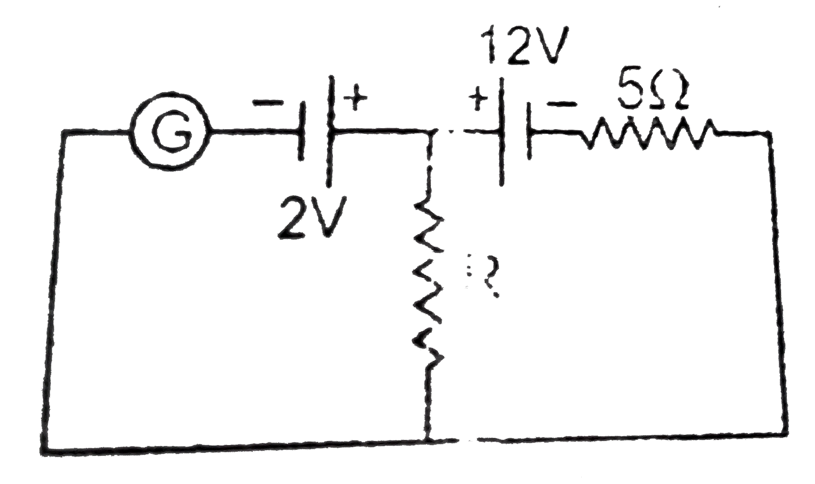
View SolutionIn the circuit shown, the galvanometer shows zero current. The value of resistance R is :
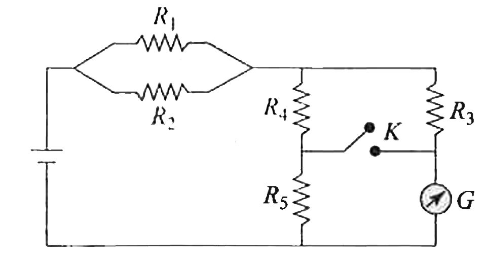
View SolutionWhether the switch K is open or closed, the reading of galvanometer is the same. If I denotes the current then :
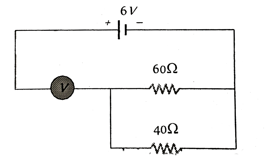
View SolutionThe measurement of voltmeter in the following circuit is
View SolutionAn ammeter and a voltmeter of resistance `R` connected in seires to an electric cell of negligible internal resistance. Their readings are `A` and `V` respecitvely. If another resistance `R` is connected in parallel with the voltmeter
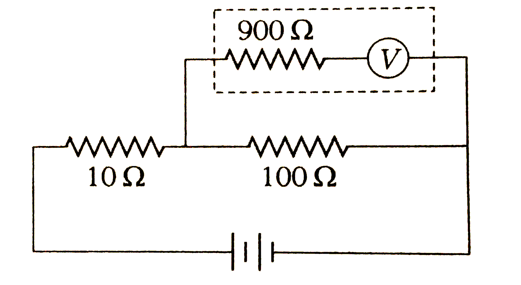
View SolutionThe potential difference across the `100Omega` resistance in the circuit is measured by a voltmeter of `900Omega` resistance. The percentage error made in reading the potential difference is
View SolutionTwo resistance of `400 Omega` and `800 Omega` are connected in series with 6 volt battery of negligible internal resistance. A voltmeter of resistance `10,000 Omega` is used to measure the potential difference across `400 Omega`. The error in measurement of potential difference in volts approximatley is
View SolutionA galvanometer having a resistance of `50 Omega`, gives a full scale deflection for a current of 0.05 A. The length (in metres) of a resistance wire of area of cross section `3 xx 10^(-2) cm?` that can be used to convert the galvanometer into an ammeter which can read a maximum of 5 A current is `("Specific resistance of the wirep "= 5 xx 10^(-7)Omega m) `
View SolutionWhat is the reading of voltmeter in the figure?

View SolutionA voltmeter of resistance 998 `Omega` is connected across a cell of emf 2 V and internal resistance `2Omega`. The potential difference across the voltmeter is
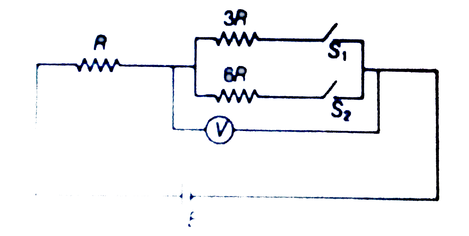
View SolutionIn the circuit shown in figure reading of voltmeter is `V_(1)` when only `S_(1)` is closed, reading of voltmeter is `V_(2)` when only `S_(2)` is closed and reading of voltmeter is `V_(3)` when both `S_(1)` and `S_(2)` are closed. Then
View SolutionA moving coil galvanometer has 150 equal divisions. Its current sensitivity is 10 divisions per milliampere and vlotage sensitivity is 2 divisions per millivolt. In order that each division reads 1 V the resistance in ohm needed to be connected in series with the coil will be
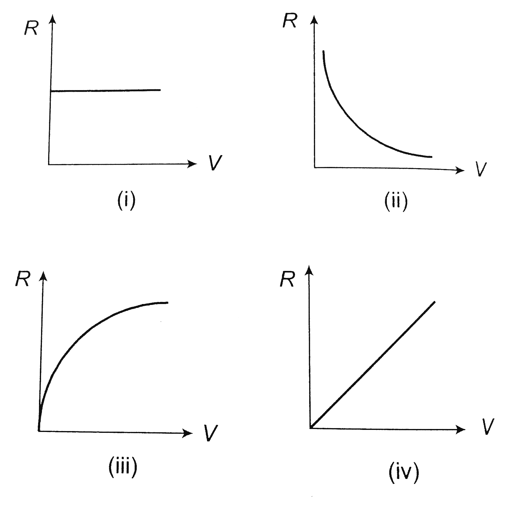
View SolutionThe graph which represents the relation between the total resistance `R` of a multi range moving coil voltmeter and its full scale deflection
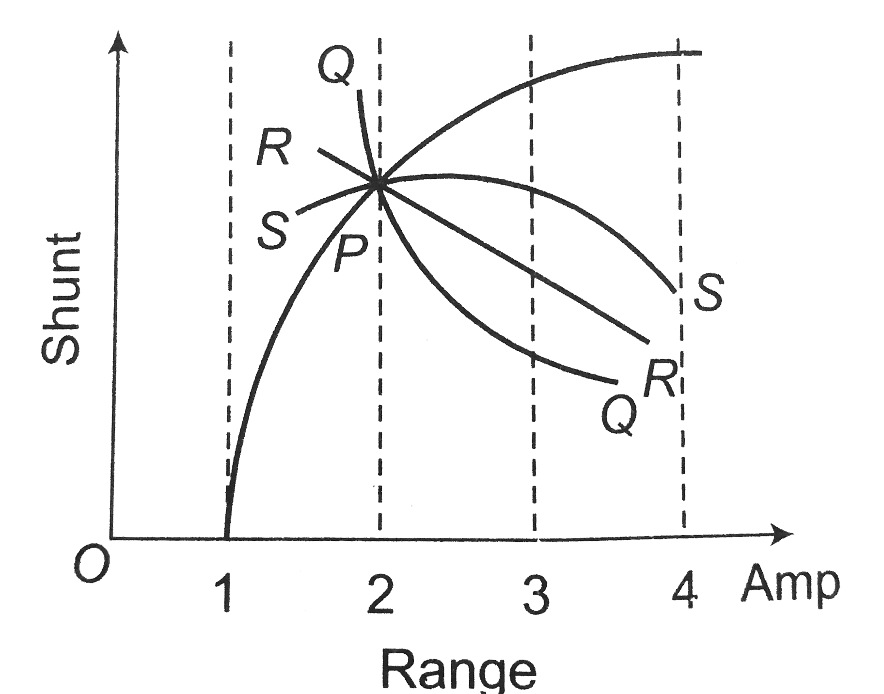
View SolutionThe ammeter has range 1 ampere without shunt. The range can be varied by using different shunt resistance. The graph between shunt resistance and range will have the nature
View SolutionIn the circuit shown here, the readings of the ammeter and voltmeter are

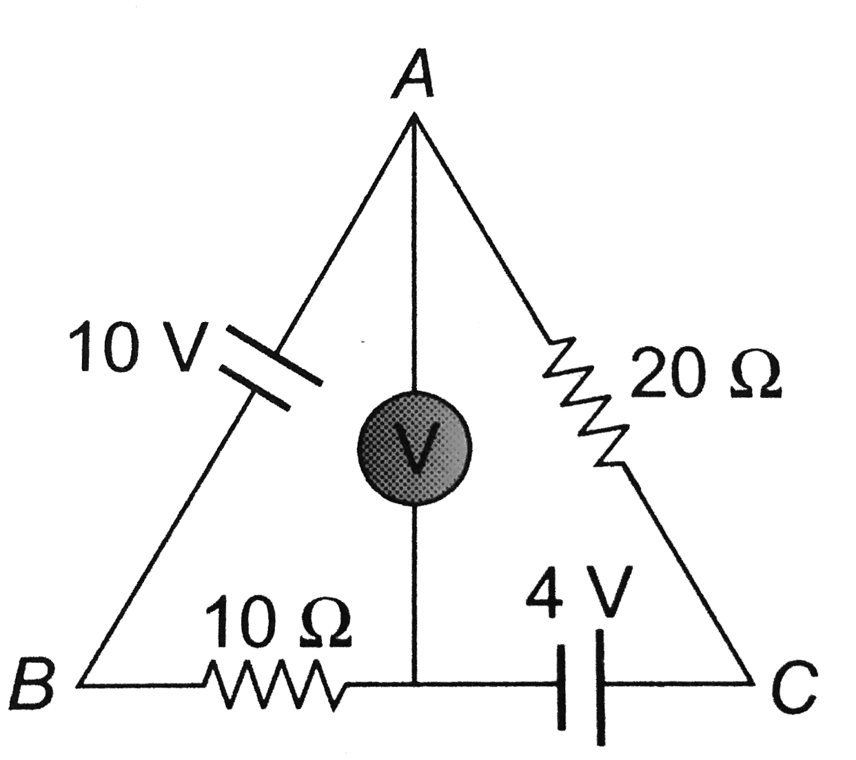
View SolutionThe reading of the ideal voltmeter in the adjoining diagram will be
View SolutionA moving coil galvanometer has 150 equal divisions. Its current sensitivity is 10 divisions per milliampere and vlotage sensitivity is 2 divisions per millivolt. In order that each division reads 1 V the resistance in ohm needed to be connected in series with the coil will be
View SolutionThe potentiometer is best for measuring voltage as:
View SolutionA cell of itnernal resitance `1.5 Omega` and of e.m.f. `1.5` volt balances `500 cm` on a potentiomter wire. If a wirr of 15 `Omega` is connected between the balance point and the cell, then tha balance point will shift
View SolutionFor comparing the e.m.f.'s of two cells with a potentiometer, a standard cell is used to develop a potential gradient along the wires. Which of the following possibilities would make the experiment unsuccessful gt
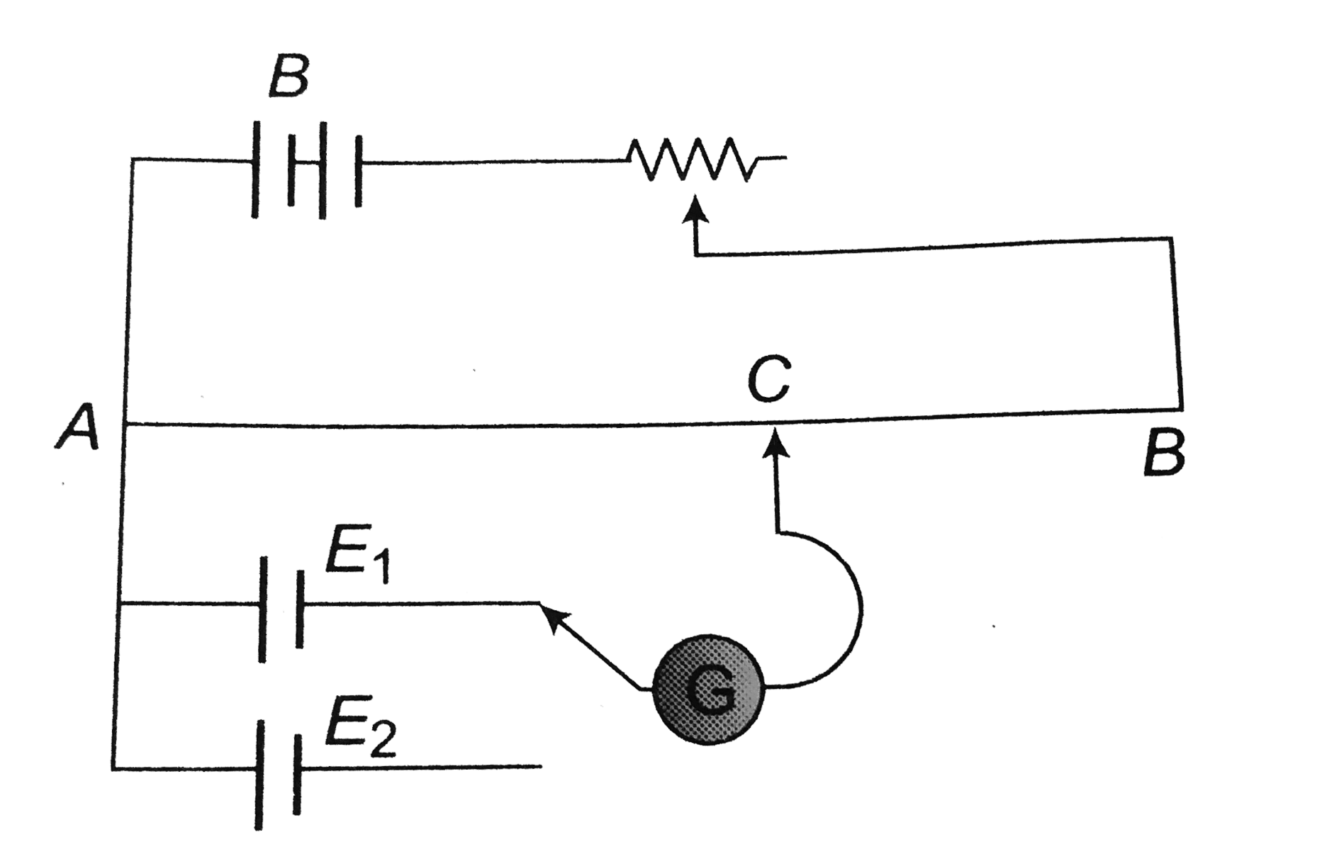
View SolutionThe circuit shown here is used to compare the e.m.f. of the two cells `E_(2) (E)_(1) gt E_(2)`. The null point is at `C` when the galvanometer is connected to `E_(1)`. When the galvanometer is connected to `E_(2)`, the null point will be
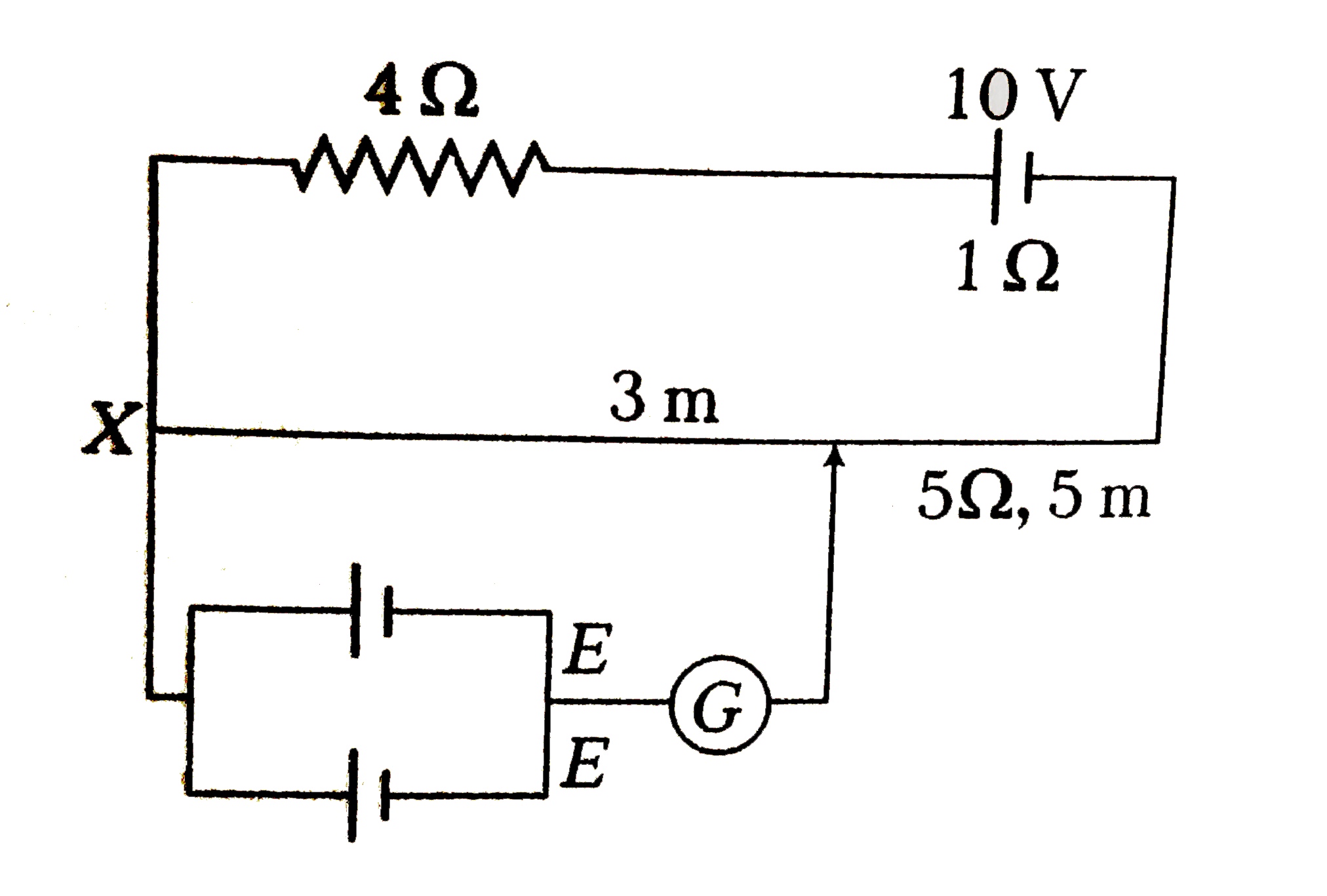
View SolutionA resistance of `4Omega` and a wire of length 5 m and resistance `5Omega` are joined in series and connected to a cell of emf 10 V and internal resistance `1Omega`. A parallel combination of two identical cells is balanced across 3 m of the wire. The emf E of each cell is ltBrgt
View SolutionThe length of a wire of a potentiometer is 100 cm, and the emf of its cell is E volt. It is employed to measure the emf of a battery whose internal resistance is `0.5Omega`. If the balance point is obtained at l = 30 cm from the positive end, the emf of the battery is
View SolutionPotentiometer wire of length `1 m` is connected in series with `490 Omega` resistance and `2 V` battery. If `0.2 mV/cm` is the potential gradient, then resistance of the potentiameter wire is approximately
View SolutionFigure `6.51` shows a simple a potentiometer circuit for measuring a small emf produced by a thermocouple.

The meter wire `PQ` has a resistance of `5 Omega`, and the driver cell has an emf of `2.00 V`. If a balance point is obtained `0.600 m` along `PQ` when measuring an emf of `6.00 mV`,
what is the value of resistance `R`?
View SolutionTwo cells of emfs approximately `5V and 10V` are to be accurately compared using a potentiometer of length 400cm
View SolutionIn meter brigde of Wheatstone bridge for measurment of resistance, the known and the unknown resistance are interchanged. The error so removed is
View SolutionIn Wheatstone's bridge `P = 9 ohm`, Q = 11 ohm`, R = 4 ohm` and `S = 6 ohm`. How much resistance must be put in parallel to the resistance `S` to balance the bridge
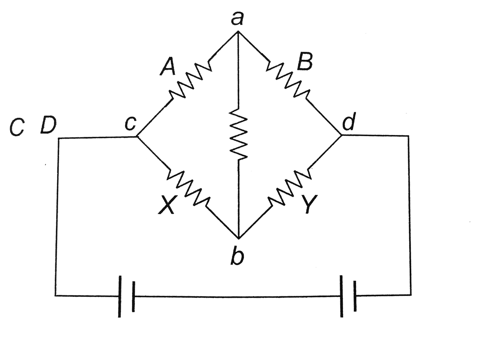
View SolutionIn the Wheatstone's bridge (shown in figure) `X = Y` and `A gt B`. The direction of the current between `ab` will be
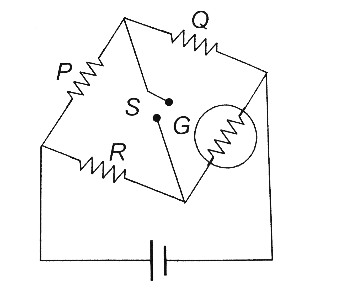
View SolutionThe firgure shows a circuit diagram of a 'Wheatstone Bridge' to measure the resistance `G` of the galvanometer The relation `(P)/(Q) = (R )/(G)` will be satisfied only when
View SolutionIn the circuit shown, a meter bridge is in its balanced state. The meter bridge wire has a resistance `.1 ohm//cm`. The value of unknown resistance `X` and the current drawn from the battery of negligible resistance is
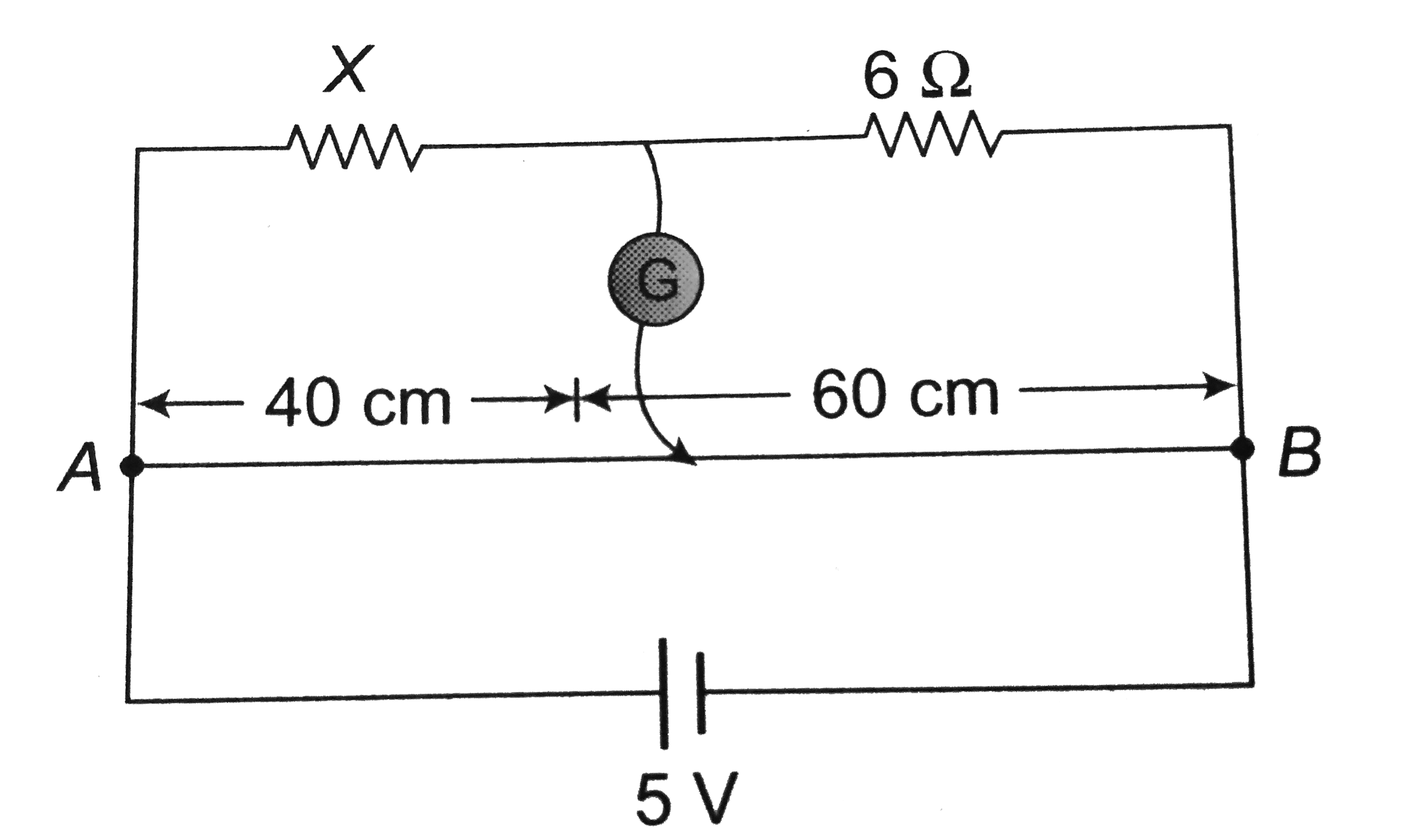
View SolutionIn a metre bridge experiemnt, null point is obtained at `20cm` from one end of the wire when resistance `X` is balanced against another resistnace `Y`. If `XltY`, then the new position of the null point from the same end,if one decides to balance a resistance of `4X`s against `Y` will be at
View SolutionTwo resistance are connected in two gaps of metre bridge. The balance point is 20 cm from the zero end. A resistance of `15 Omega` is connected in series with the smaller of the two. The null point shifts to 40 cm. The value of the smaller resistance in ohm is
View SolutionIn a practical wheat stone bridge circuit as shown, when one more resistance of `100 Omega` is connected in parallel with unknown resistance 'x', then ratio `l_1//l_2` become '2'`l_1` is balance length , AB is a uniform wire. Then value of 'x' must be :
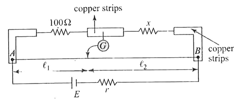
View SolutionA resistance R is to be measured using a meter bridge. Student chooses the standard resistance S to be `100Omega`. He finds the null point at `l_(1) = 2.9cm`. He is told to attempt to improve the accuracy. Which of the following is a useful way?
View Solution`R_1, R_2, R_3` are different values of `R, A, B` and `C` are the null points obtained corresponding to `R_1, R_2` and `R_3` respectively. For which resistor, the value of X will be the most accurate and why?
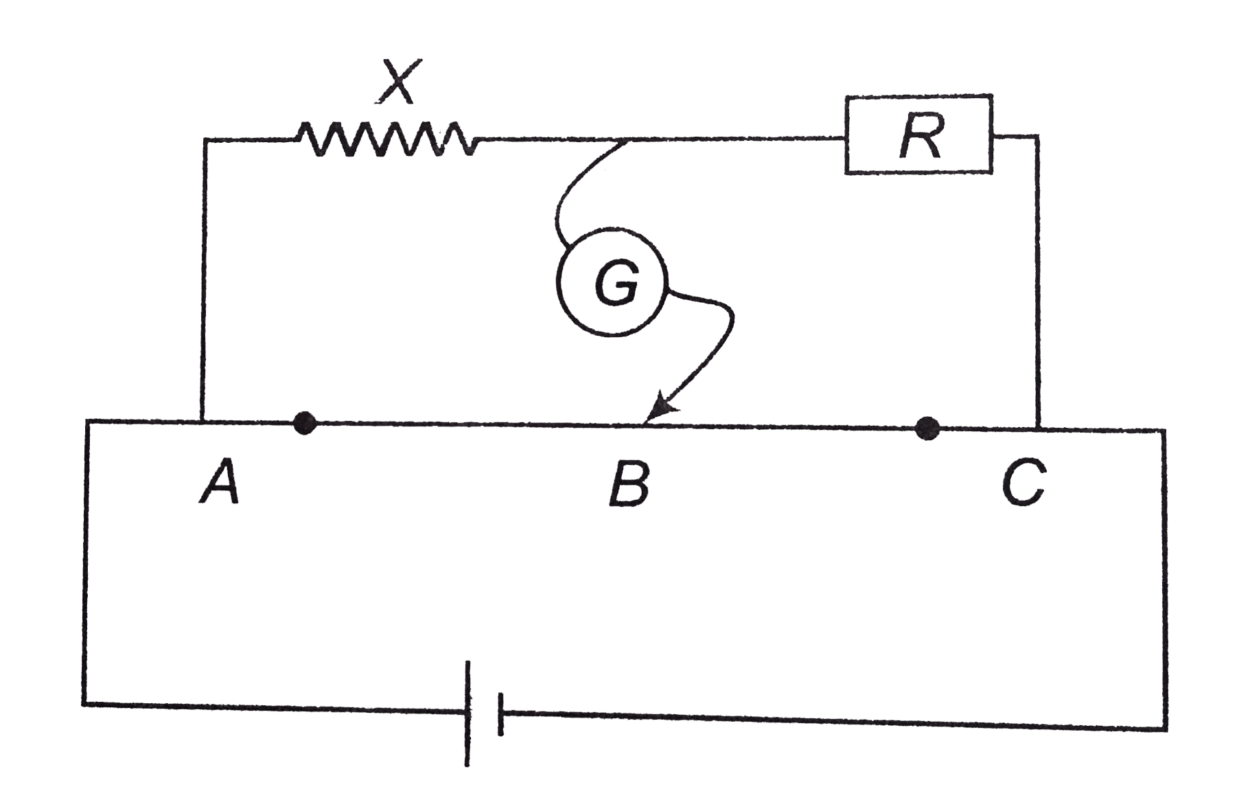
View SolutionIn the shows arrangement of a meter bridge, if `AC` corresponding to null deflection of galvanometer is x, what would be its value if the radius of the wire `AB` is doubled?

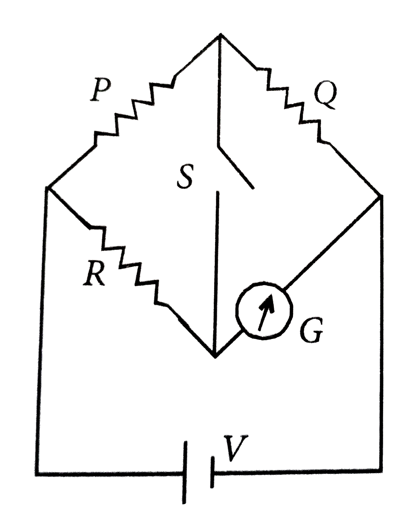
View SolutionIn the circuit `PneR`, the reading of the galvanometer is same with switch S open or closed. Then
View Solution
Single Correct questions and complete solutions for chapter ELECTRICAL MEASURING INSTRUMENTS of CENGAGE PHYSICS (ENGLISH) of Class 12