Complete Solutions to Exercise 3.1 of chapter ELECTROMAGNETIC INDUCTION of Class 12 book with complete answers and questions
| Class 12 | PHYSICS |
| Chapter | ELECTROMAGNETIC INDUCTION |
| CENGAGE PHYSICS | Exercise 3.1 |
| Number Of Questions | 15 |
| Academic Year | 2023-24 |
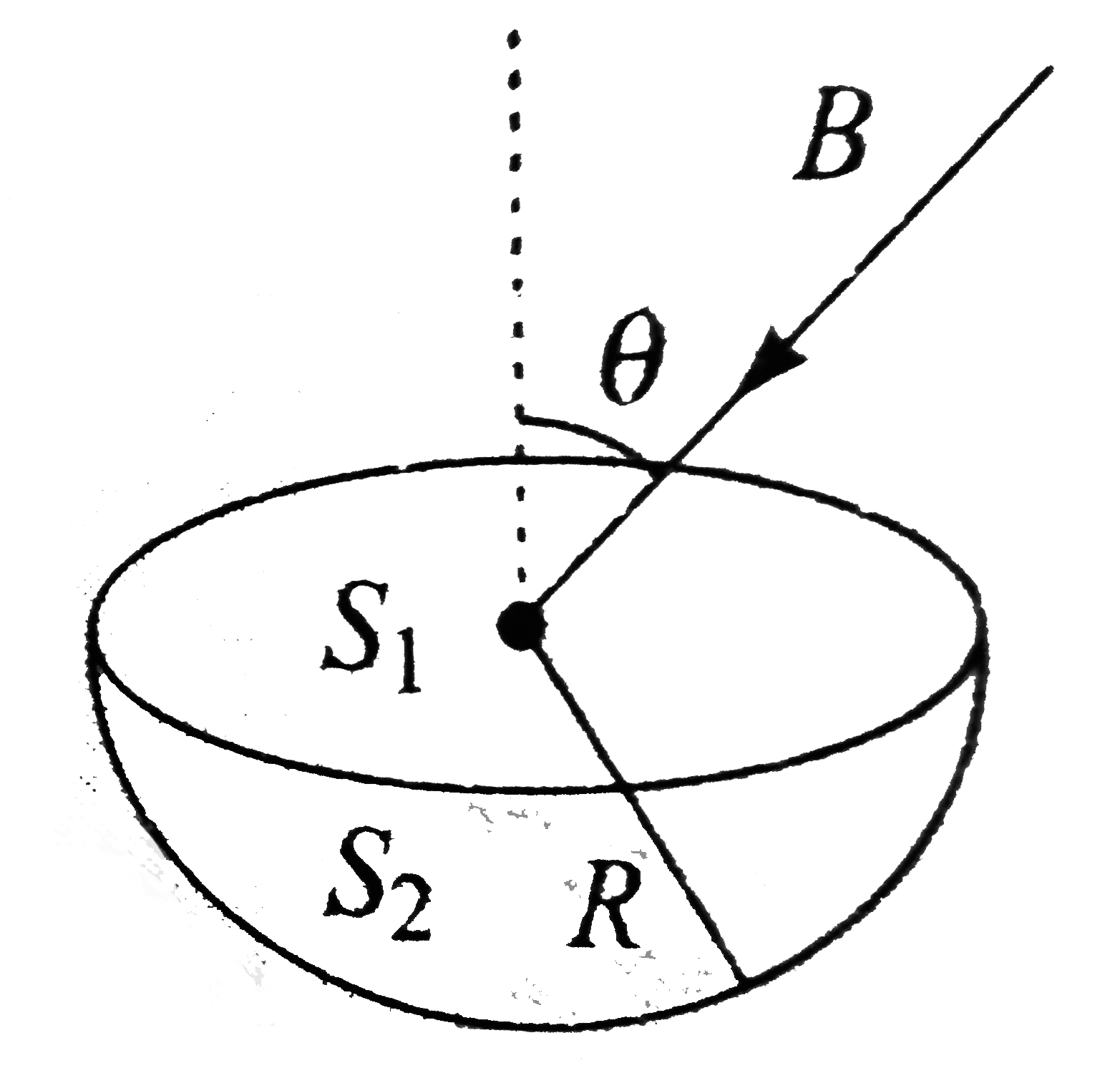
Consider the hemispherical closed surface as shown in Fig. 3.19. if the hemisphere is a uniform magnetic field that makes an angle `theta` with the vertical, calculate the magnetic flux
(a) through the flat surface `S_(1)`.
(b) through the hemisphere surface `S_(2)`.
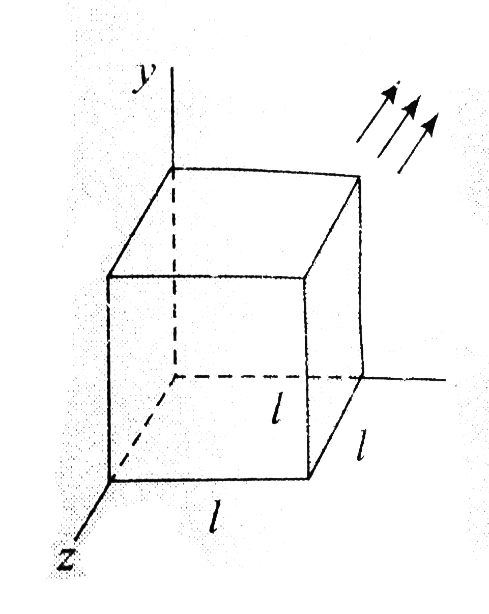
View SolutionA cube of edge length `l = 2.50 cm` is positioned as shown in Fig. 3.20. A uniform magnetic field given by `vec(B) = (5.00 hat(i) + 4.00hat(j) + 3.00hat(k)) T` exists throughout the region.
(a) Calculate the flux through the shaded face.
(b) What is the total flux through the six faces ?
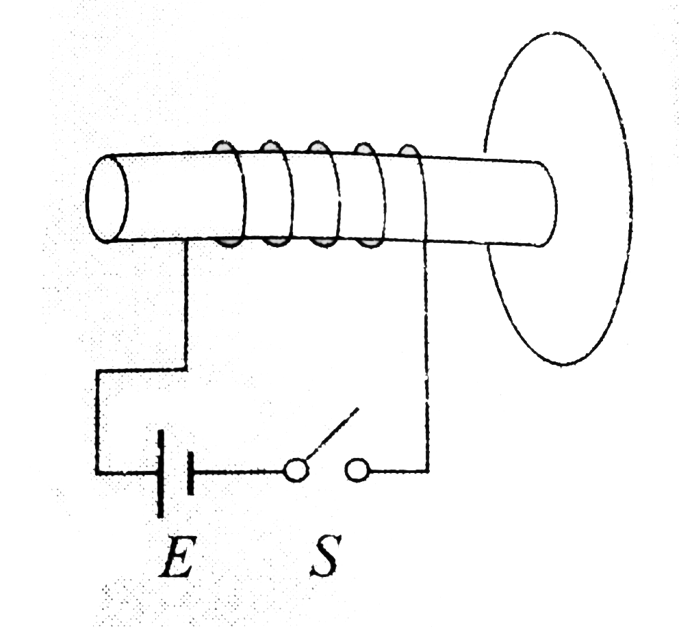
View SolutionA conducting ring is placed near a solenoid as shown in Fig.3.21. Find the direction of the induced current in the ring.
(a) At the instant the switch in the circuit containing the solenoid is closed.
(b) After the switch has been closed for a long time.
(c) At the instant the switch is opened.
View SolutionIdentify the direction of induced current as seen from the above in the following cases.
(a)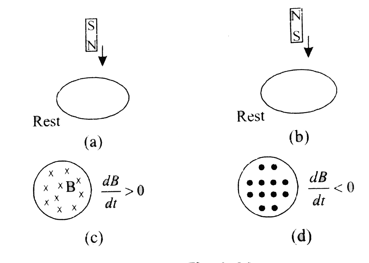
View SolutionUsing Lenz's law, determine the direction of the current in resistor `ab` in Fig. 3.23 when
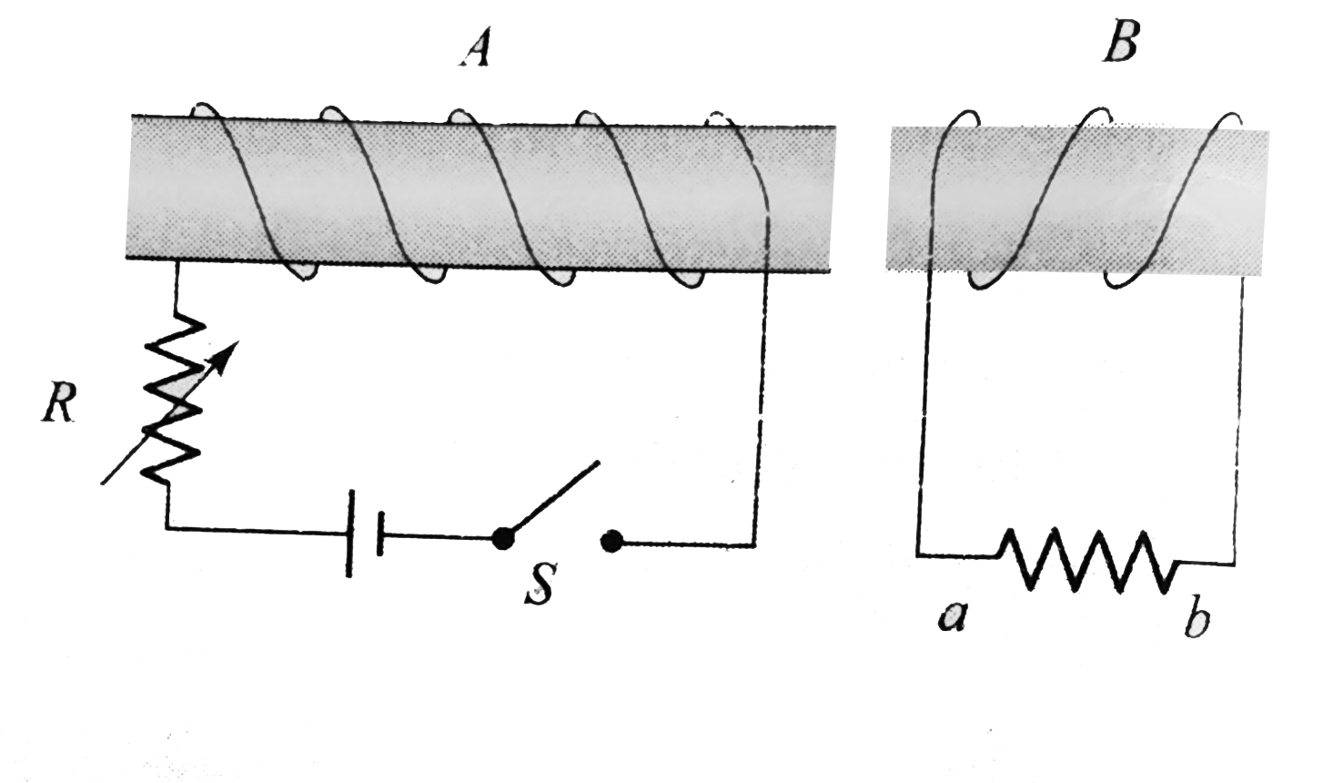
(a) switch `S` is opended after having been closed for several minutes.
(b) coil `B` is brought closer to coil `A` with the swich closed. ltbr. ( c) the resistance of `R` is decreased while the switch remains closed.
View SolutionA carboard tube is wrapped with two winding of insulated wire wound in opposite directions as shown in Fig. 3.24. Terminal `a and b` of winding `A` may be connected to a battery through a reversing switch. State whether the induced current in the resistor `R` from left to right or from right to left in the following cicumstances.
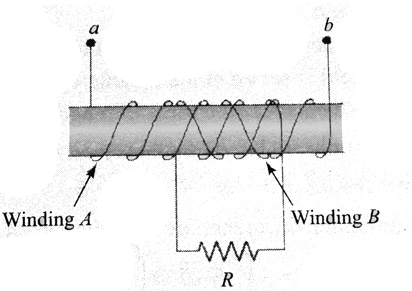
(a) The current in winding `A` is from `a to b` and is increasing.
(b) The current in winding `A` is from `b to a` and is decreasing.
( c) The current in winding `A` is from `b to a` and is increasing.
View SolutionA small, circular ring is inside a larger loop that is connected to a battery and a switch as shown in Fig. 3.25. Use Lenz's law to find the direction of the current induced in the small ring
(a) just after switch `S` is closed,
(b) after `S`has been closed for a long time,
( c) just after `S` has been reopened after being closed for a long time. ltbr.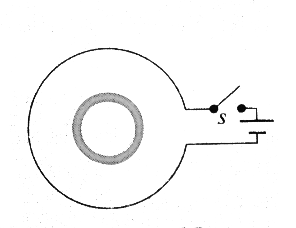
View Solution(a). Predict the polarity of capacitor `C` as shown in Fig. 3.26 when poles `S` and `N` of two identical magnets approach the coil from opposote sides with equal velocity. The plane of the loop containing the capacitor is perpendicualr to the plane of the paper.

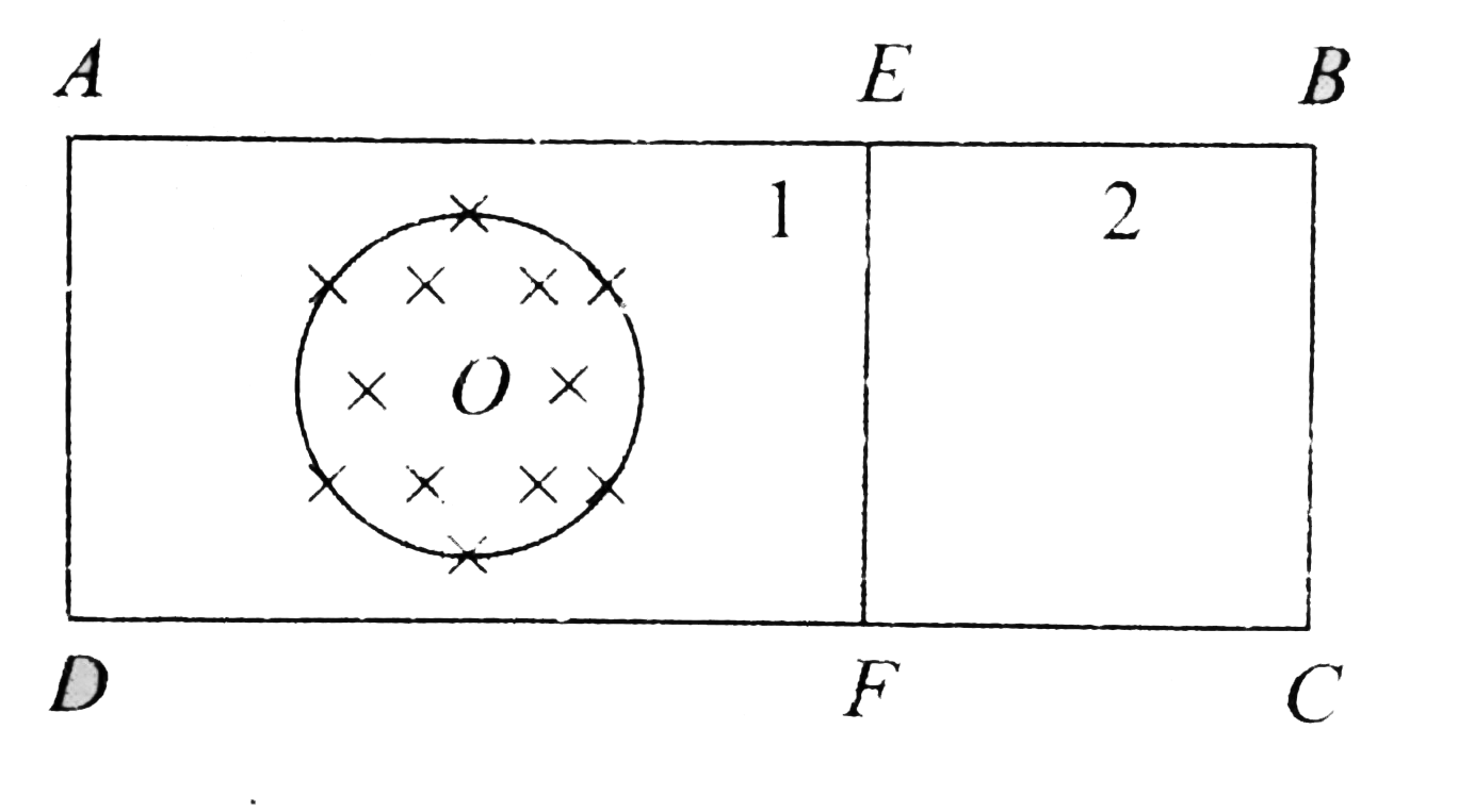
(b). A magnetic field perpendicular to the plane of a rectangular frame of wire is concentrated about `O`. If the field decreases, will there be any emf induced in loop `1`? What about loop `2`? Explain why.
View SolutionA coil is placed in a constant magnetic field. The magnetic field is parallel to the plane of the coil as shown in Fig. 3.28. Find the emf induced in the coil if `B` increasing.
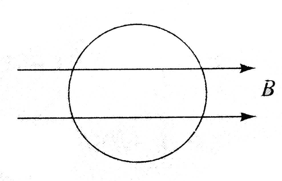
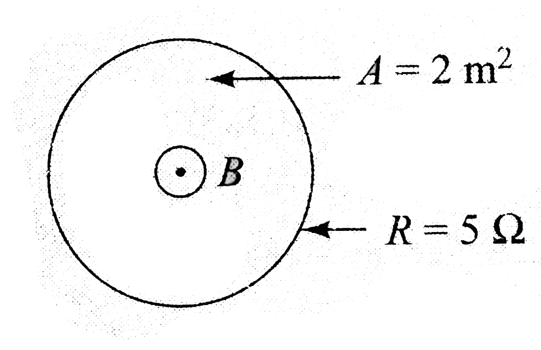
View SolutionShows a coil placed in a decreasing magnetic field applied perpendicular to the plane of the coil. The magnetic field is decreasing at a rate of `10 T s^(-1)`. Find out current in magnitude and direction of current.
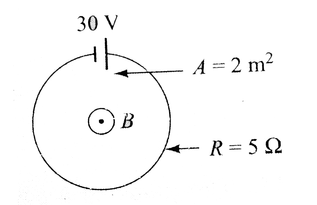
View SolutionShows a coil placed in a magnetic field decreasing at a rate of `10 T s^(-1)`. There is also a source of emf `30V` in the coil. Find the manitude and direction of the current in the coil.
View SolutionA square loop of wire with resistance `R` is moved at constant speed `v` across a uniform magnet field confined to a square region whose sides are twice the lengths of those of the square loop
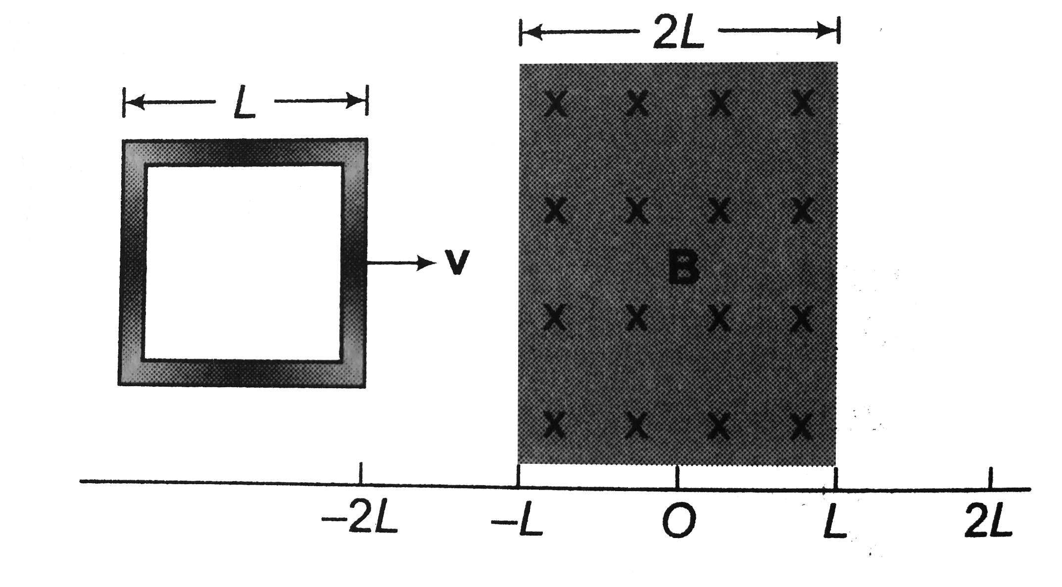
(a) Sketch a graph of the external forces `F` needed to move the loop at constant speed, as a function of to sketch a graph of the external force `F` need tho coordinate `x`, from`x=-2L` to `x=+2L`. (The coordinate `x` is measured from the centre of the oignetic field region to the centre of the loop. It is negative when the centre of the loop is to the left, of the centre of the magnetic field region. Take positive force to be to the right). (b) Sketch a graph of the induced current in the loop as a function of `x`. Take counterclockwise currents to be positive.
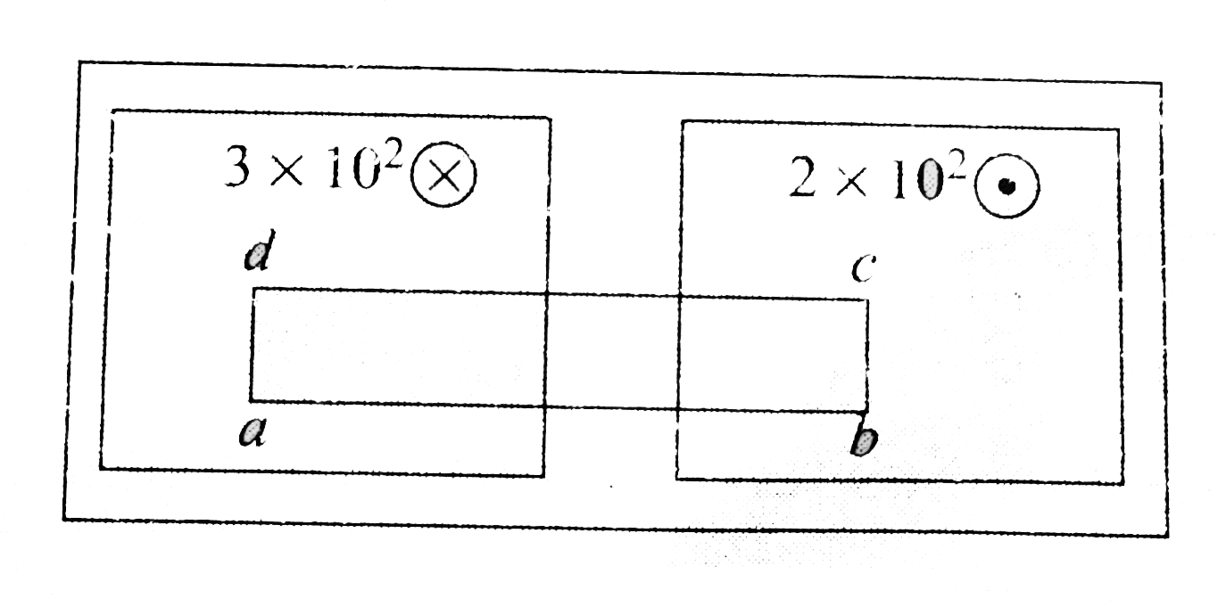
View SolutionTwo magnetic fields exits in the two regions as shown in . A loop abcd of `40 xx 10 cm` id placed in the field. The resistance per unit length of the loop is `r = 2Omegacm^(-1)`. All of a sudden, the loop is given a velocity `v_(0) = 20cm s^(-1)` towards roght. What is the potential difference `V_(c ) - V_(b)` ?
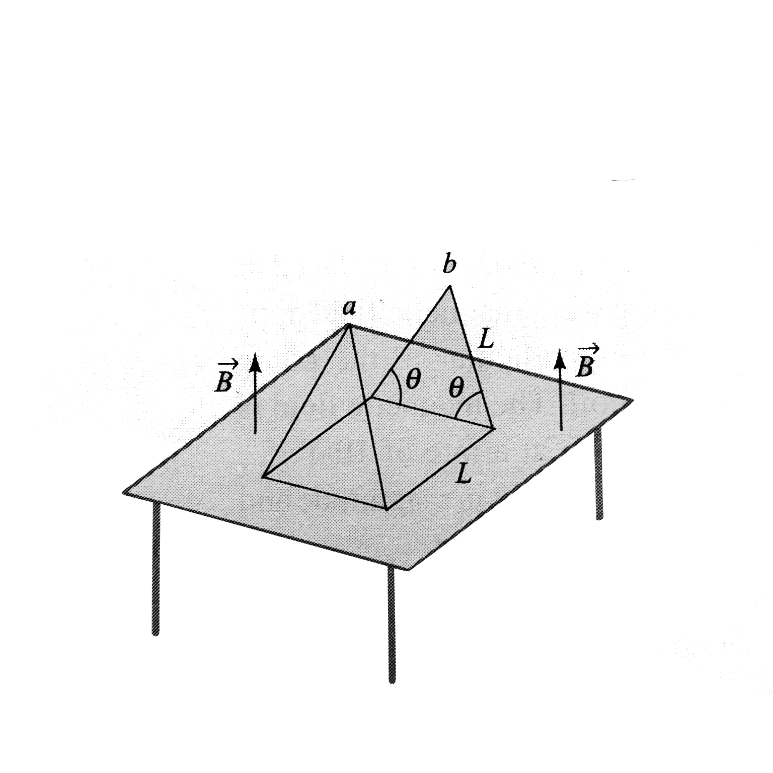
View SolutionThe wire shown in is bent in the shape of a tent, with `theta = 60.0^(@)` and `L = 1.50 m`, and placed in a uniform magnetic field of magnitude `0.300 T` perpendicular to the tabletop. The wire is rigid but hinged at points `a and b`. If the tent is flattened out on the table in `0.100 s`, what is the average induced emf in the wire during this time?
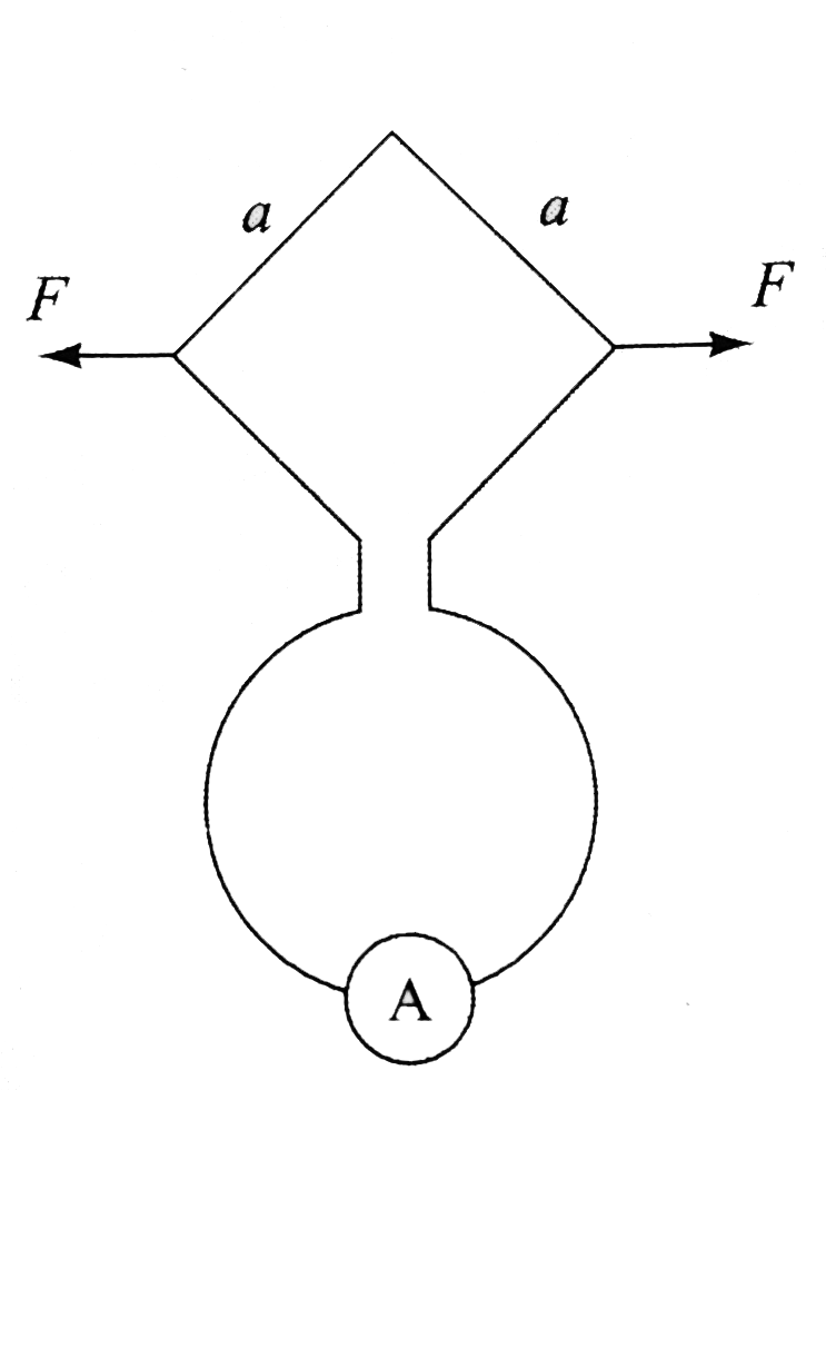
View SolutionThe plane of a square loop of wire edge length `a = 0.200 m` is perpendicualr to the Earth's magnetic field at a point where `B = 15.0 muT`, as shown in . The total resistance of the loop and the wires connecting it to a sensitive ammeter is `0.50 Omega`. If the loop is suddenly collapsed by horizontal forces as shown, what is the total charge passing through the ammeter?
View Solution
Exercise 3.1 questions and complete solutions for chapter ELECTROMAGNETIC INDUCTION of CENGAGE PHYSICS (ENGLISH) of Class 12
All Exercises from CENGAGE PHYSICS Class 12 PHYSICS ELECTROMAGNETIC INDUCTION
- Archives Asserton - Reasoning
- Archives Fill In The Blanks
- Archives Multiple Correct
- Archives Single Correct
- comprehensive
- comprehensive type
- compression type
- Exercise 3.1
- Exercise 3.2
- Exercises Asserton - Reasoning
- Exercises Integer
- Exercises Linked Comprehension
- Exercises Multiple Correct
- Exercises Single Correct
- Exercises Subjective
- Illustration
- Multiple correct Answer Type
- single correct
- single correct
- single correct answer
- Single Correct Answer Type
- Solved Example