Complete Solutions to Exercises Single Correct of chapter ELECTROMAGNETIC INDUCTION of Class 12 book with complete answers and questions
| Class 12 | PHYSICS |
| Chapter | ELECTROMAGNETIC INDUCTION |
| CENGAGE PHYSICS | Exercises Single Correct |
| Number Of Questions | 79 |
| Academic Year | 2023-24 |
A horizontal straight conductor when placed along south-north direction falls under gravity, there is
View SolutionTwo circular, similar, coaxial loops carry equal currents in the same direction. If the loops are brought nearer, what will happen?
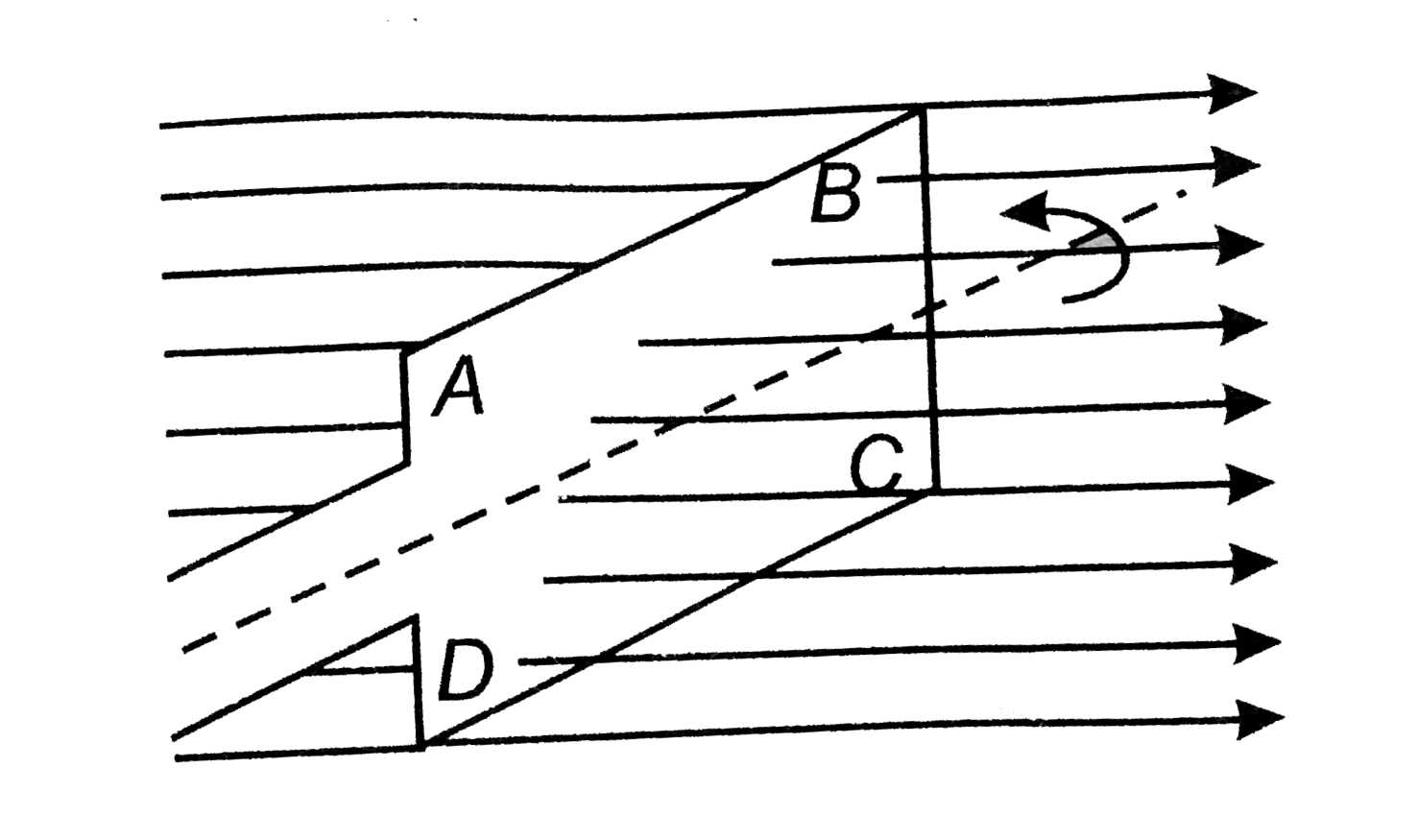
View SolutionA rectangular coil ABCD is rotated anticlockwise with a uniform angular velocity about the axis shown In the fig. the axis of rotation of the coil as well as the magnetic field `B` are horizontally.the induced emf in the coilwould be minimum when the plane of the coil
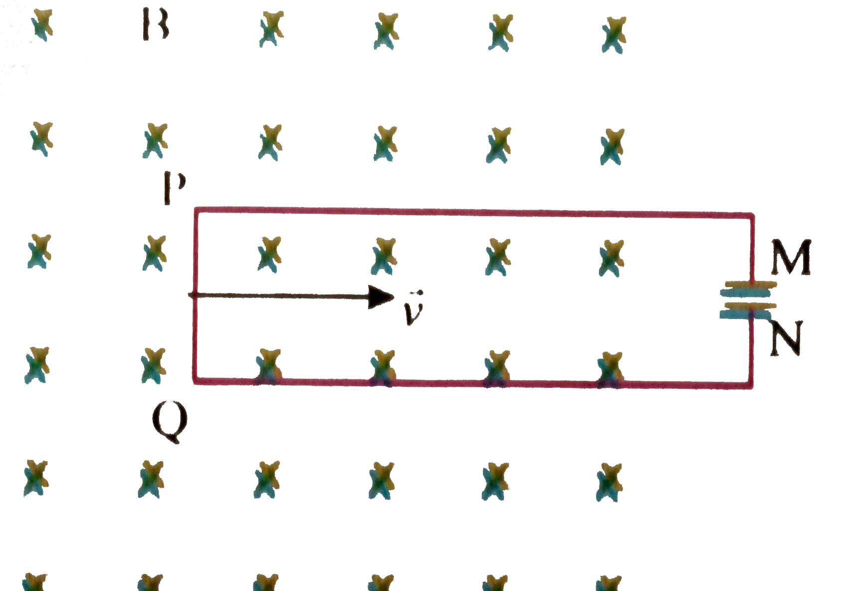
View SolutionA rod `PQ` is connected to the capacitor plates. The rod is placed in a magnetic field `(B)` directed downwards perpendicular to the plane of the paper. If the rod is pulled out of magnetic field with velocity `vec(v)` as shown in Figure.
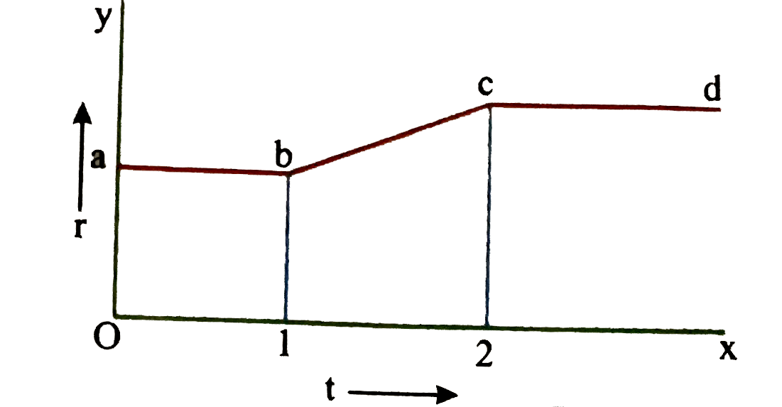
View SolutionA flexible wire bent in the form of a circle is place in a uniform magnetic field perpendicularly to the plane of the coil. The radius of the coil changes as shown in Figure. The graph of magnetude of induced emf in the coil is represented by
View SolutionA thin circular ring of area A is held perpendicular to a uniform magnetic field of induction B. A small cut is made in the ring and a galvanometer is connected across the ends such that the total resistance of the circuit is R. When the ring is suddenly squeezed to zero area, the charge flowing through the galvanometer is
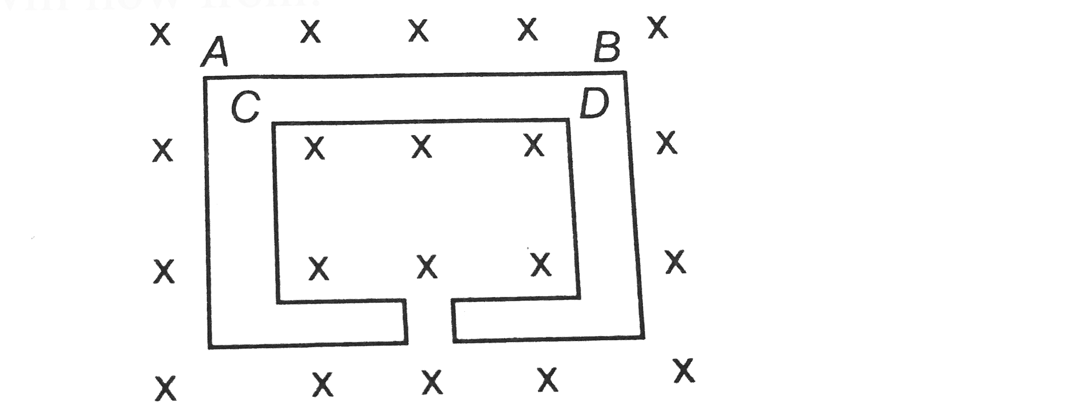
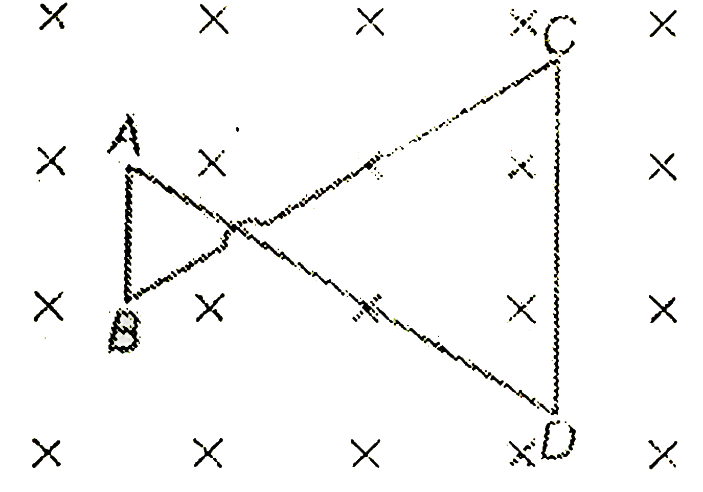
View SolutionA wire is bent to form the double loop shown in figure. There is a uniform magnetic field directed into the plane of the loop. If the magnitude of this field is decreasing current will flow from:
View SolutionA wire is sliding as shown in Figure. The angle between the acceleration and the velocity of the wire is
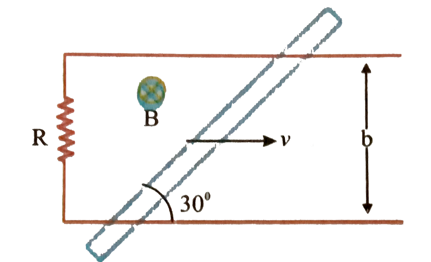
View SolutionA conducting ring of radius `'r'` is rolling without slipping with a constant angular velocity `omega` (figure). If the magnetic field strengh is `B` and is directed into the page the emf induced across `PQ` is
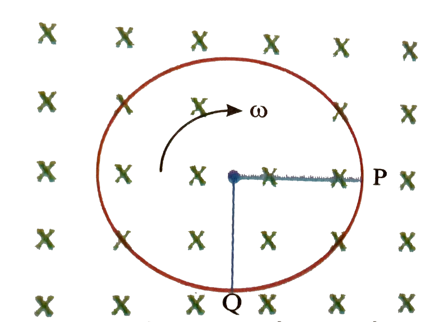
View SolutionA `0.1` m long coductor carrying a current of 50 A is held perpendicular to a magnetic field of `1.25` mT. The mechanical power required to move the conductor with a speed of `1 ms^(-1)` is
View SolutionA conducting wire `xy` of lentgh `l` and mass `m` is sliding without friction on vertical conduction rails `ab` and `cd` as shown in figure. A uniform magnetic field `B` exists perpendicular to the plane of the rails, `x` moves with a constant velocity of
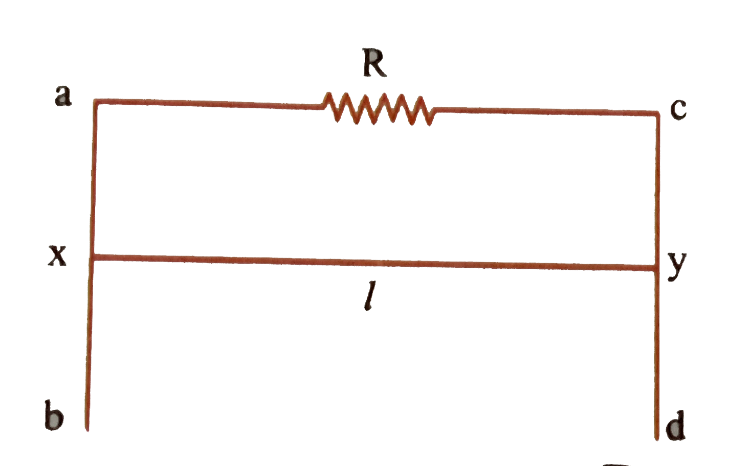
View SolutionThe linear loop has an area of `5 xx 10^(-4)m^(2)` and a resistance oof `2 Omega`. The larger circular loop is fixed and has a radius of `0.1m`. Both the loops are concentric and coplanner. The smaller loop is rotated with an angular velocity `omegarads^(-1)` about its dismeter. The magnetic flux with the smaller loop is
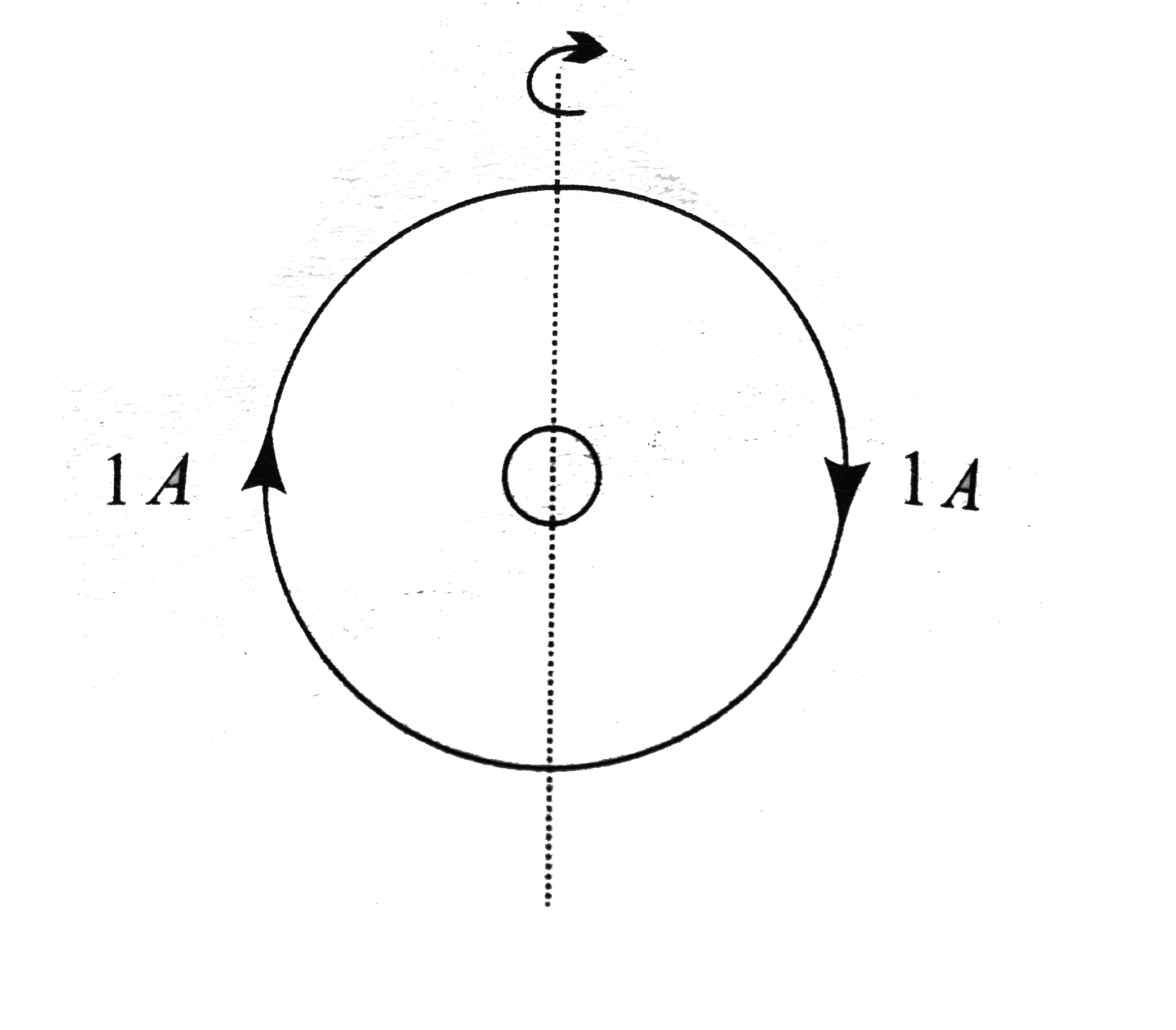
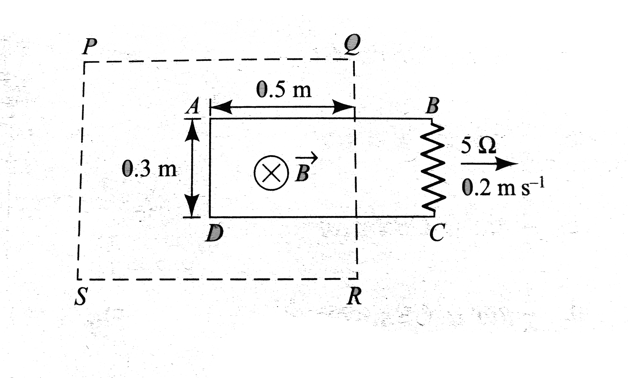
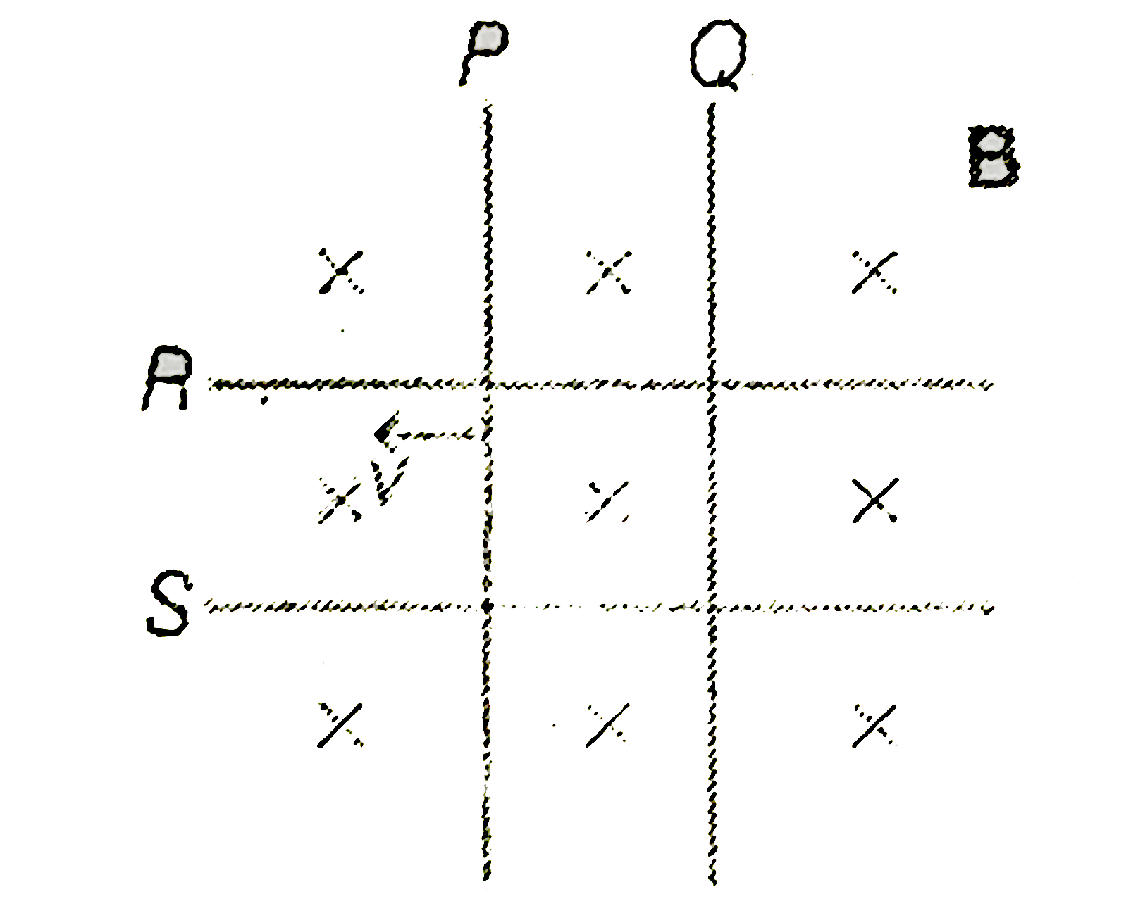
View SolutionA circuit `ABCD` is held perpendicular to the uinform magnetic field of `B = 5 xx 10^(-2)T` extending over the region `PQRS` and directed into the plane of the paper. The cicuit is moving out of the field at a uin form speed of `0.2 m s^(-1)` for `1.5 s`. During this time, the current in the `5 Omega` resistor is
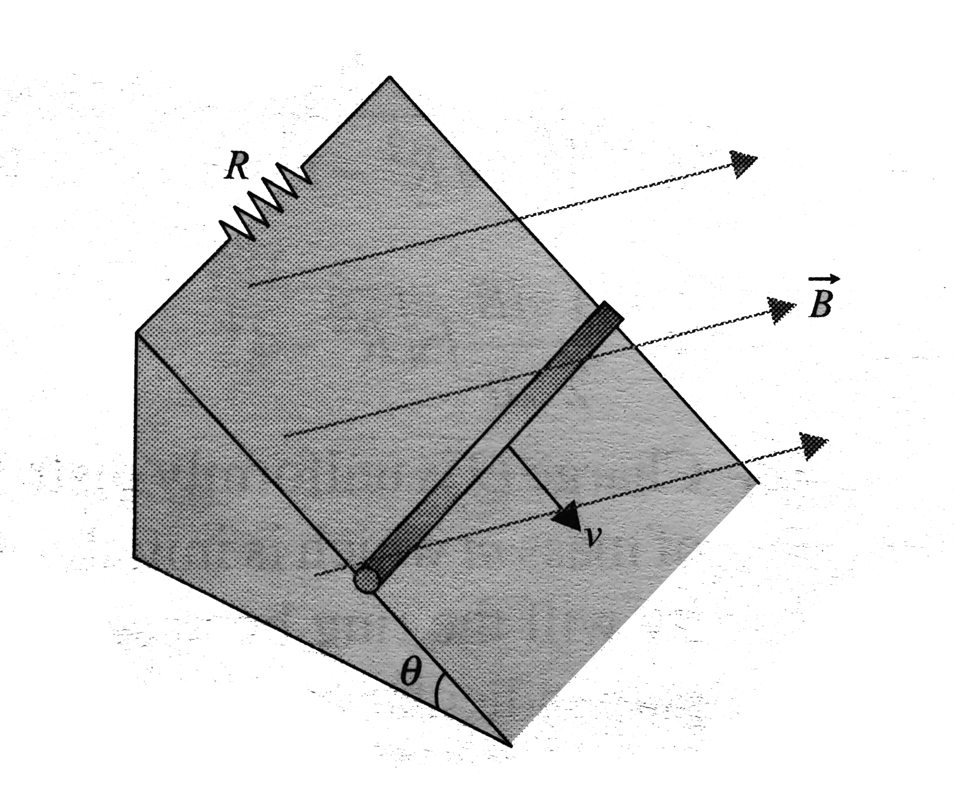
View Solutiona conducting wire os mass `m` slides down two smooth conducting bars, set at an angle `theta` to the horizontal as shown in . The separatin between the bars is `l`. The system is located in the magnetic field `B`, perpendicular to the plane of the sliding wire and bars. The constant velocity of the wire is
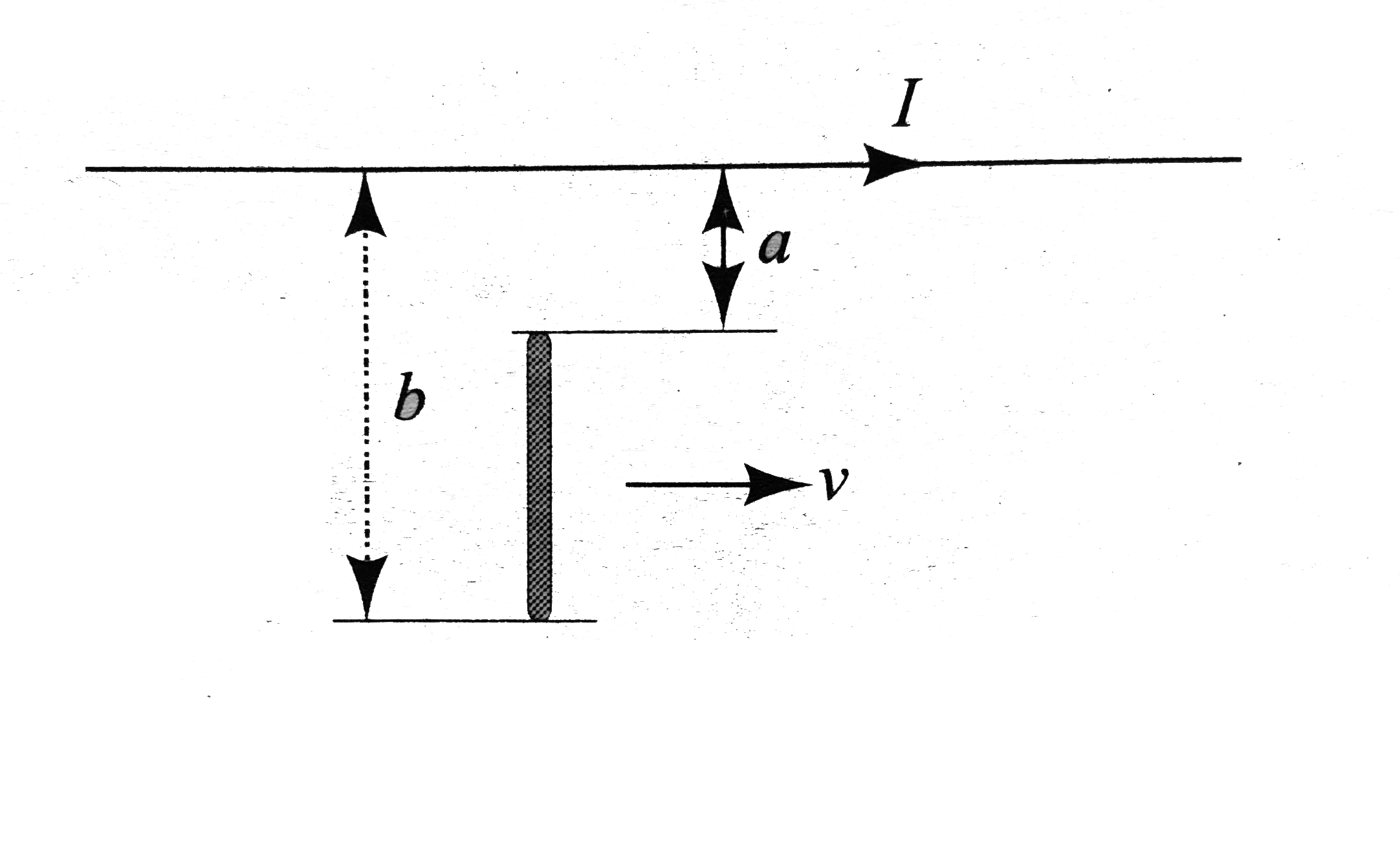
View SolutionShows a copper rod moving with velocity `v` parallel to a long straight wire carrying current `= 100 A`. Calculate the induced emf in the rod, where `v = 5 m S^(-1)`, `a = 1 cm` , `b = 100cm`.
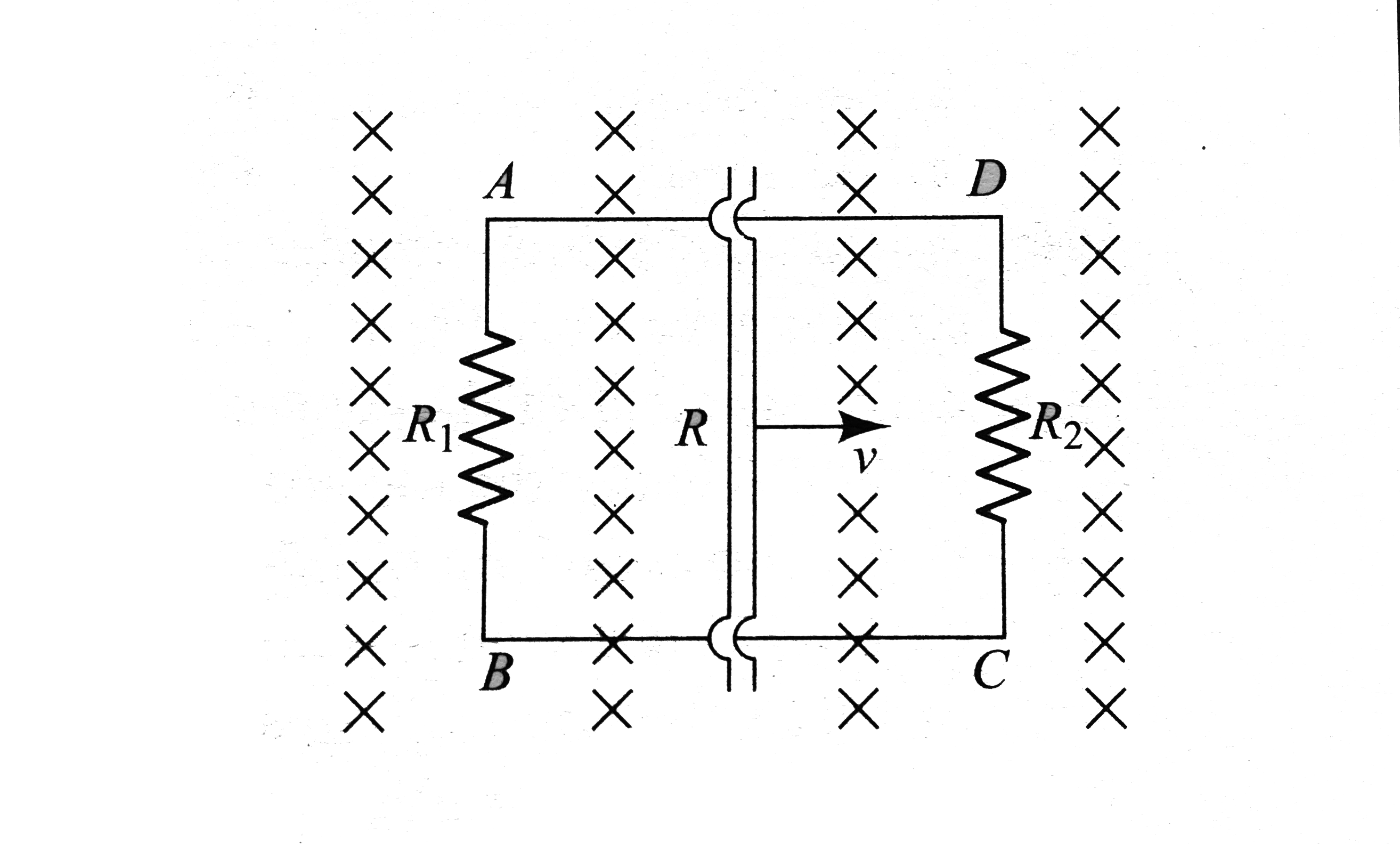
View SolutionA rectangular loop with a sliding conductor of length `l` is located in a uniform magnetic field perpendicular to the plane of the loop . The magnetic induction is `b`. The resistances `R_(1)` and `R_(2)`, respectively. Find the current through the conductor during its motion to the right with a constant velocity `v`.
View SolutionA wire ab of length l, mass m and resistance R slided on a smooth, thick pair of metallic rails joined at the bottom as shown in . The plane of the the rails makes an angle `theta` with the horizontal. A vertical magnetic field B exists in the ragion. if the wire slides on the rails at a constant speed v, show that `B = sqrt(mg R sin theta)/(vl^2 cos^theta)`.
(##HCV_VOL2_C38_E01_076_Q01##)
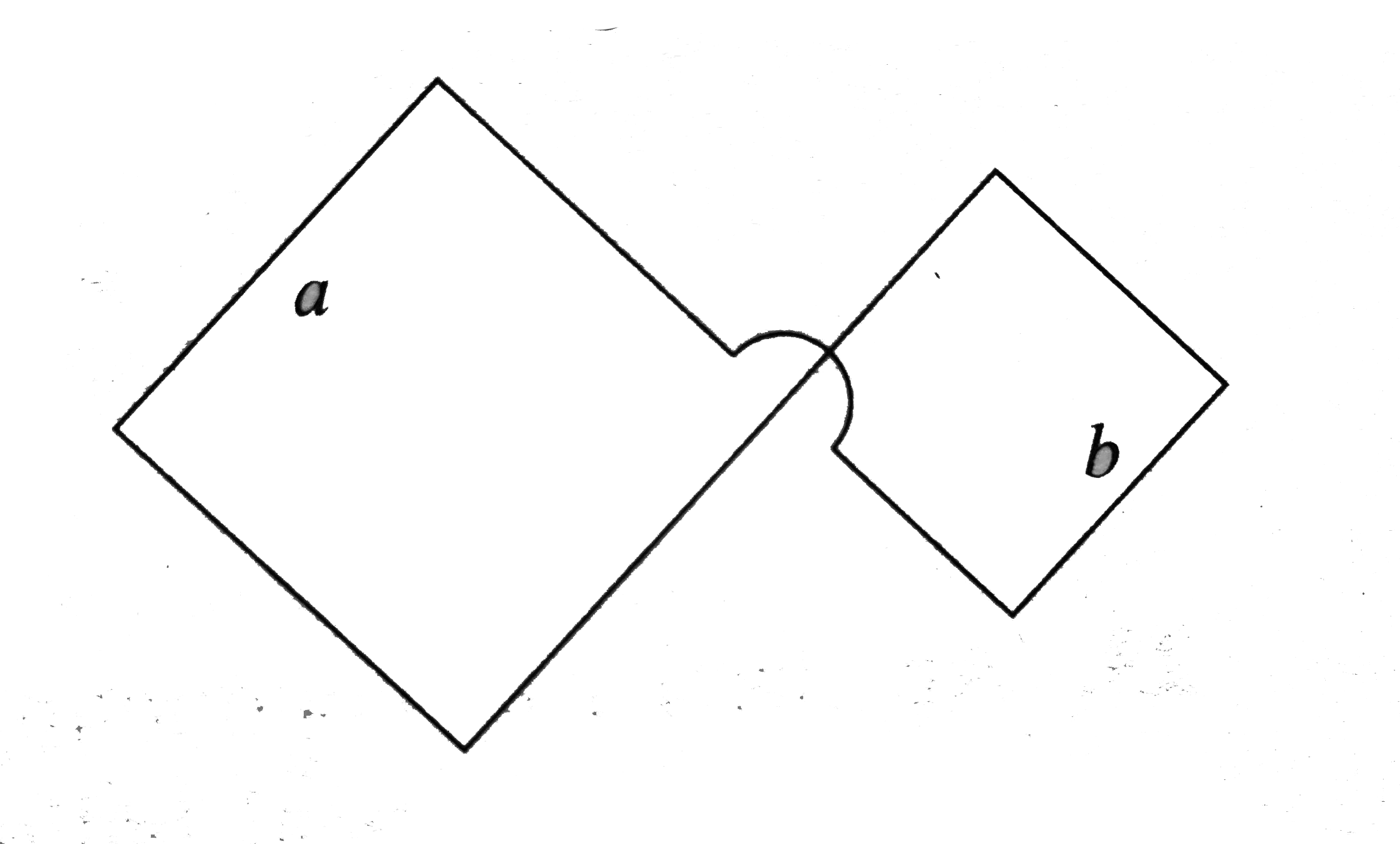
View SolutionA plane loop, shaped as two squares of sides `a = 1m` and `b = 0.4m` is introduced into a uniform magnetic field `_|_` to the plane of loop . The magnetic field varies as `B = 10(-3)sin(100t) T`. The qamplitude of the current induced in the loop if its resistance per unit length is `r = 5 mOmega m^(-1)` is
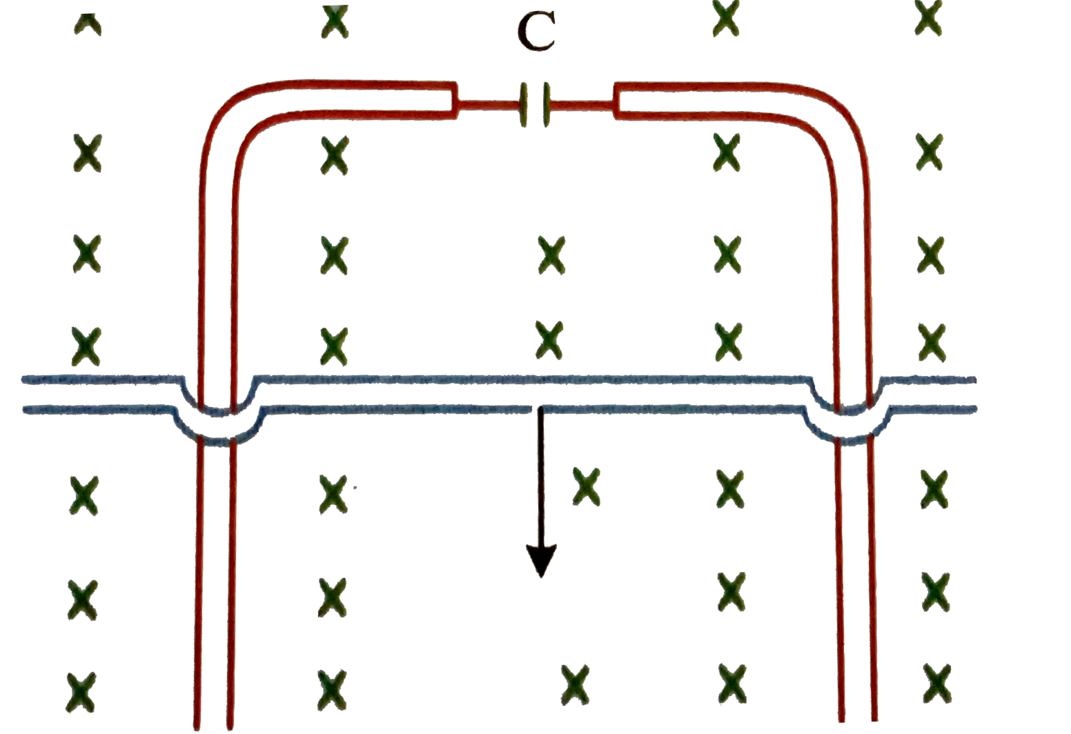
View SolutionA conductor of length `l` and mass `m` can slide without any friction along the two vertical conductors connected at the top through a capacitor. A uniform magnetic field `B` is set up `_|_` to the plane of paper. The acceleration of the conductor
View SolutionA rectangular loop of sides 10 cm and 5 cm with a cut is stationary between the pole pieces of an electromagnet.
The magnetic field of the magnet is normal to the loop. The current feeding the electromagnet is reduced, so that the field decreased from its initial value of 0.2 T at the rate of `0.02Omega`. If the cut is joined and the loop has a resistance of `2.0Omega`, then the power dissipated by the loop as heat is
View SolutionA magnetic flux through a stationary loop with a resistance `R` varies during the time interval `tau` as `phi=at(tau-t)`. Find the amount of heat the generated in the loop during that time
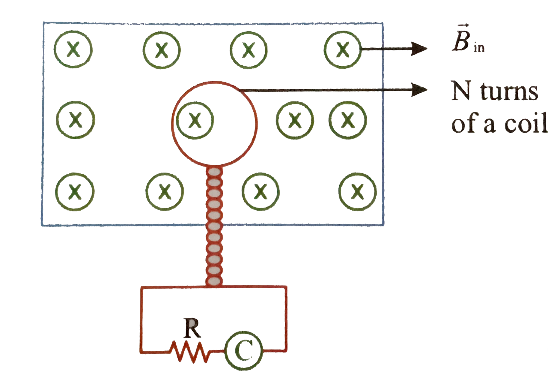
View SolutionA flip coil consits of `N` turns of circular coils which lie in a uniform magnetic field. Plane of the coils is perpendicular to the magnetic field as shown in figure. The coil is connected to a current integrator which measures the total charge passing through it. The coil is turned through `180^(@)` about the diameter. The charge passing through the coil is
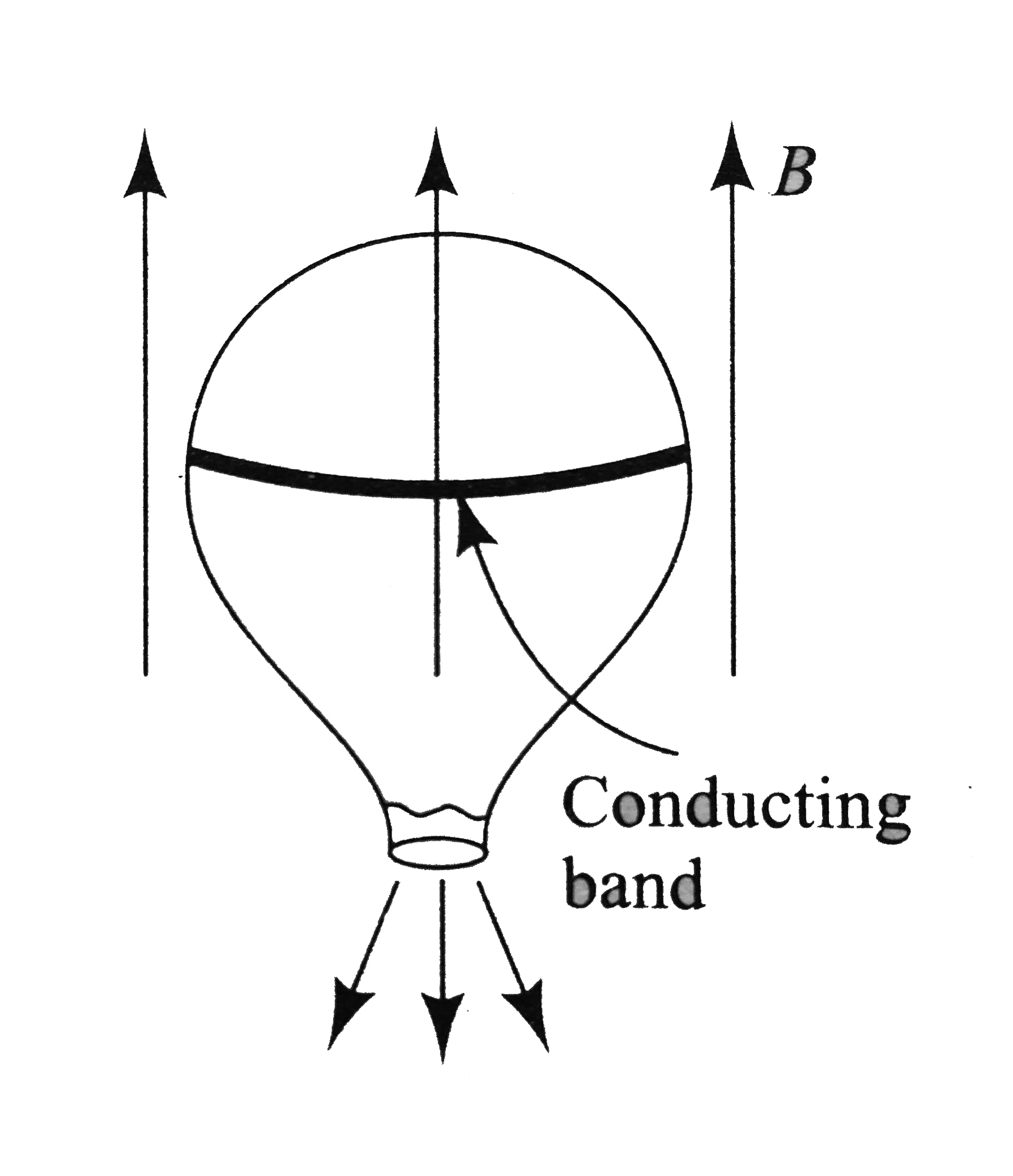
View SolutionAn elasticized conducting band is around a spherical ballon . Its plane through the center of the balloon. A uniform nmagnetic field of magnitude `0.04T` is directed perpendicular to the plane of the band. Air is let out of the balloon at `100 cm^(3) s^(-1)` at an instant when the radius of the balloon is `10 cm`. The induced emf in the band is
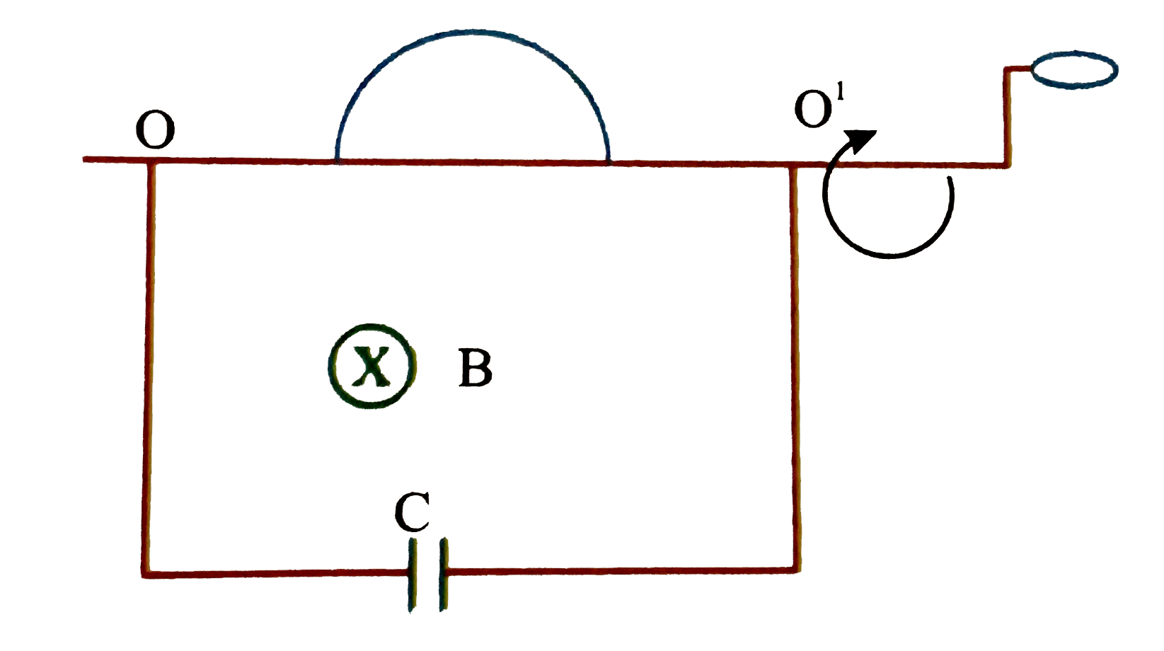
View SolutionA copper rod is bent inot a semi-circle of radius a and at ends straight parts are bent along diameter of the semi-circle and are passed through fixed, smooth and conducting ring `O` and `O'` as shown in figure. A capacitor having capacitance `C` is connected to the rings. The system is located in a uniform magnetic field of induction `B` such that axis of rotation `O O'` is perpendicular to the field direction. At initial moment of time `(t = 0)`, plane of semi-circle was normal to the field direction and the semi-circle is set in rotation with constant angular velocity `omega`. Neglect the resistance and inductance of the circuit. The current flowing through the circuit as function of time is
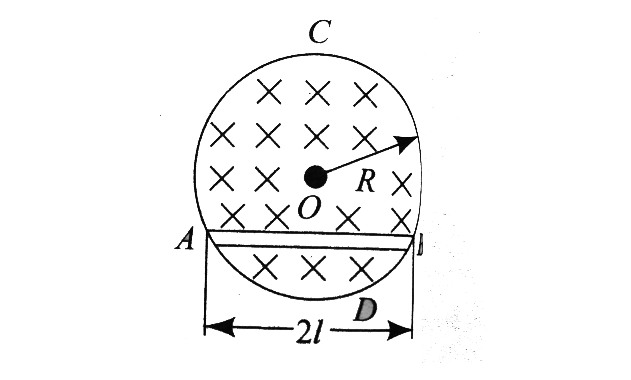
View Solutiona uniform magnetic field of induction `B` fills a cylindrical volume of radius `R`. A rod `AB` of length `2l` is placed as shown in . If `B` changing at the rate `dB//dt`, the emf that is produced by the changing magnetic field and that acts between the ends of the rod is
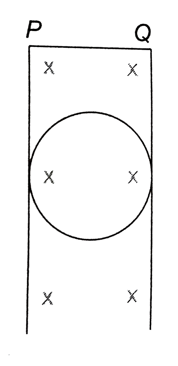
View SolutionCharge `Q` is uniformly distributed on a thin insulating ring of mass `m` which is initially at rest. To what angular velocity will the ring be accelerated when a magnetic field `B`, perpendicular to the plane of the ring, is switched on ?
View SolutionA vertical ring of radius `r` and resistance on `R` falls vertically. It is in contact with two vertical rails which are joined at the top. The rails are without friction and resistance. There is a horizontal uniform, magnetic field of magnitude `B` perpendicular to the plane of the ring and the rails. When the speed of the ring is `v` , the current in the section `PQ` is
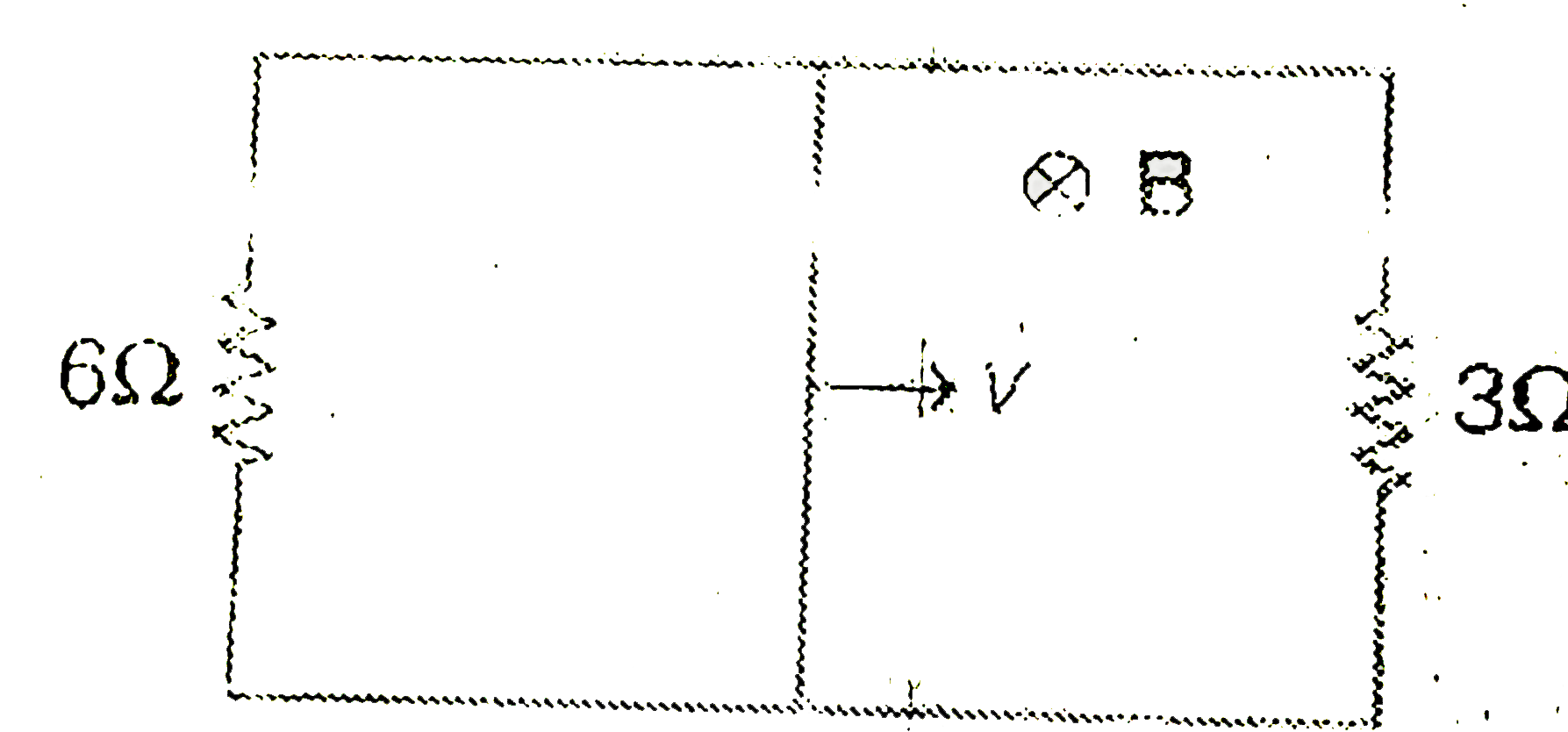
View SolutionA rectangular loop with a sliding connector of length l=10m` is the situated in a uniform magnetic for B=2T perpendicular to the plane of the loobs. Resistance of conductor is `r=2Omega`. Two resistances at a`6Omega and 3Omega` are connected as shown in the figure. The external force required to keep the conductor moving with a constant velocity v=2m/s
View SolutionA metal rod of resistance `20Omega` is fixed along diameter of a conducting ring of radius 0.1m and on x-y plane. There is a magnetic field B=(50t) . The ring roatates with an angular velocity `omega=20rad//s` about its axis. An external resistance resistance `10Omega` is connected cross the centre of the ring an rim. The current through external resistance is
View SolutionA metal disk of radius a rotates with a constant angular velocty `omega` about its axis. The potential difference between the centre and the rim of the disc is (m=mass of electron, e=charge on electron)
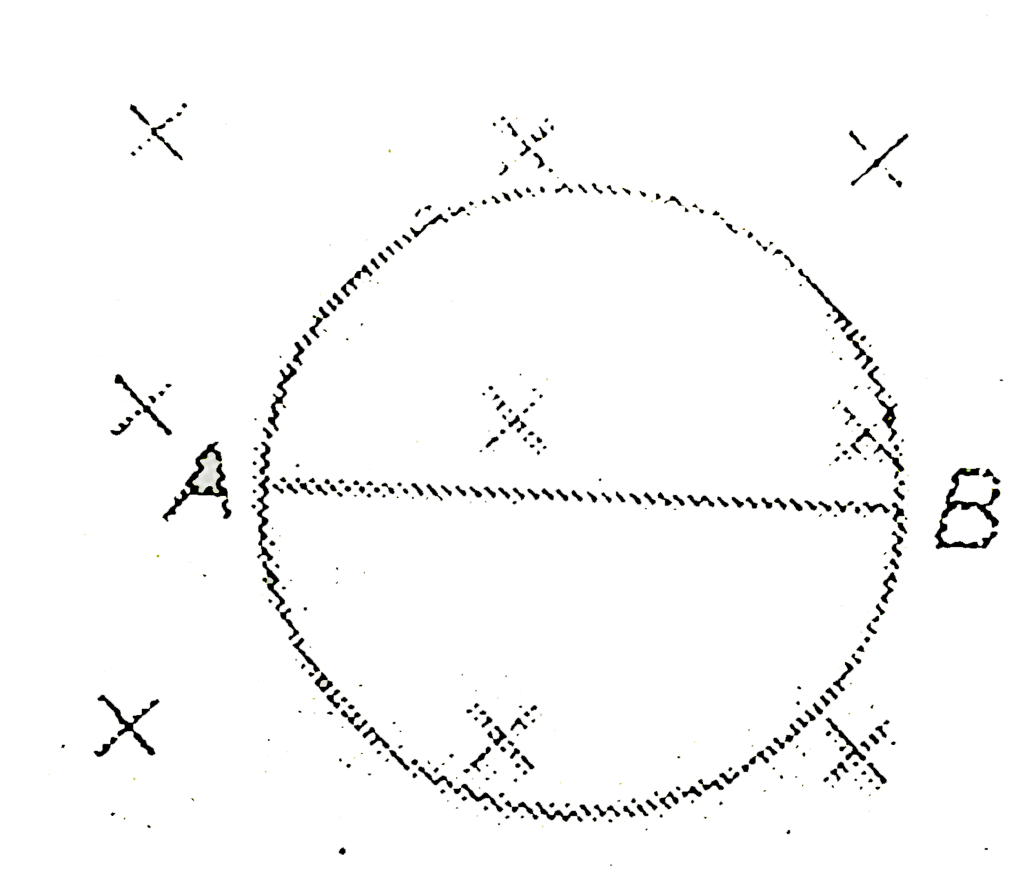
View SolutionThe radius of the circular conducting loo[ shown in the figure is R. Mangetic field is decreasing at a constant rate a. Resistance per init length of the loop is `rho`. Then current in wire AB is (AB is one of the diameters).
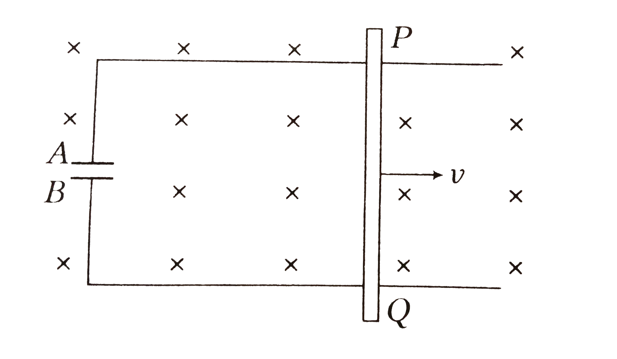
View SolutionA conducting rod PQ of length L = 1.0 m is moving with a uniform speed `v=2ms^(-1)` in a uniform magnetic field B = 4.0 T directed into the paper. A capacitor of capacity C = 10`muF` is connected as shown in figure. Then,
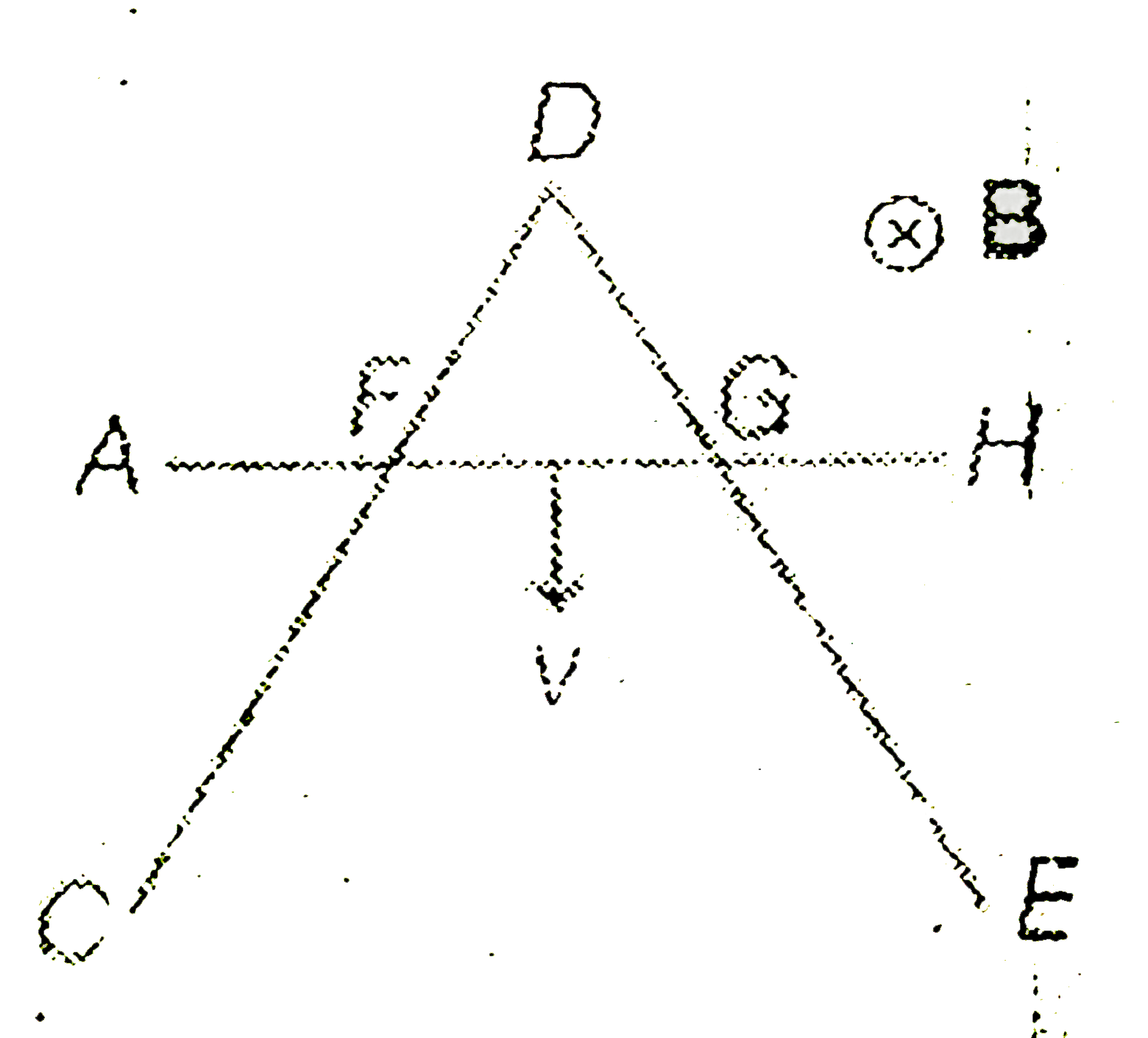
View SolutionA long conductin gwire AH is moved over a conducitn triangular wire CDE with a constant velocity v in a uniform magnetic field B directed into the paper. Resistance per unit length of each wire is `rho`. Then
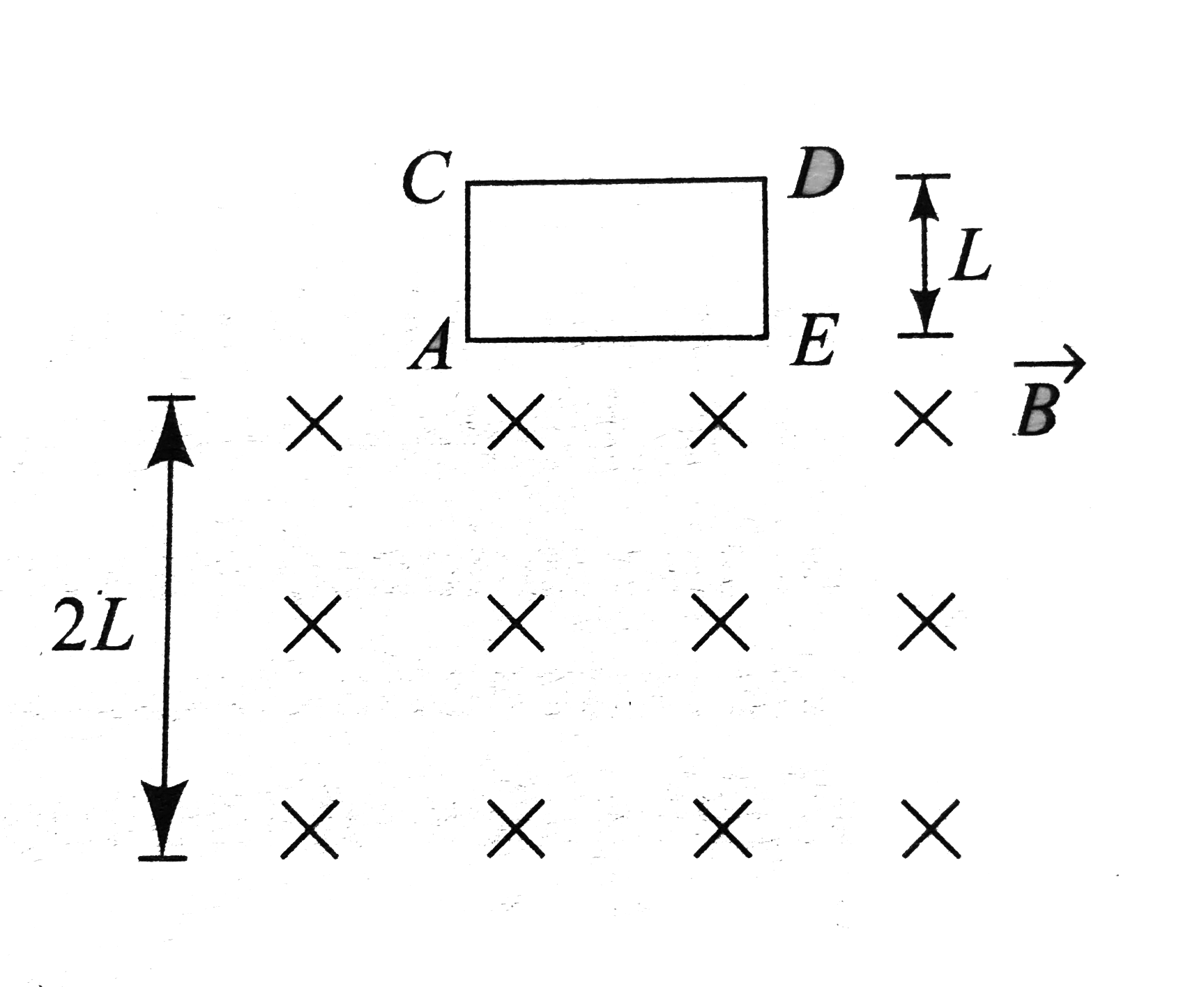
View SolutionA square coil `ACDE` with its plane vertically is released from rest in a horizontal uniform magnetic field `vec(B)` of length `2L` . The accelaration of the coilis
View SolutionA conducting wire frame is placed is placed in a magnetic field which is directed into the paper. The magnetic field is increasing at a costant rae. The directions of induced currents in wires AB and CD are
View SolutionAn equilateral triangular loop `ADC` having some resistance is pulled with a constant velocity `v` out of a uniform magnetic field directed in to the paper. At time `t = 0`, side `DC` of the loop at is at edge of the magnetic field.
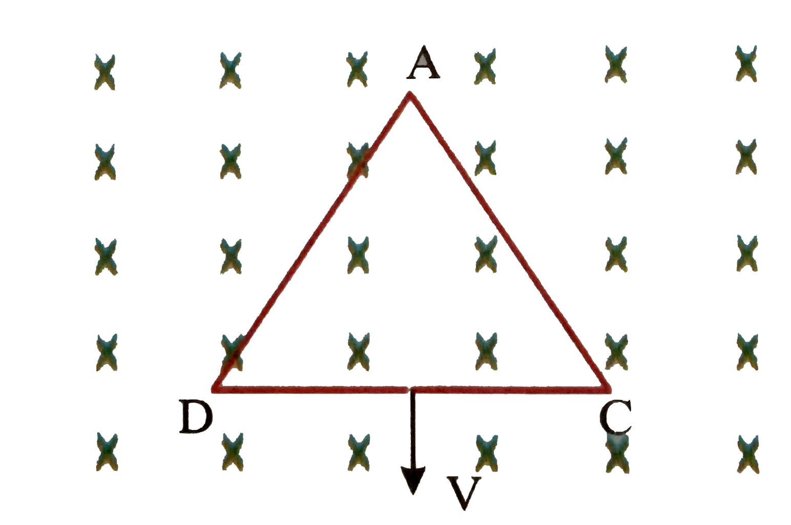
The induced current `(i)` versus time `(t)` graph will be as
View SolutionFigure show a square loop of side `0.5 m` and resistance `10Omega`. The magnetic field has a magnitude `B=1.0T`. The work done in pulling the loop out of the field slowly and uniformly in `2.0s` is
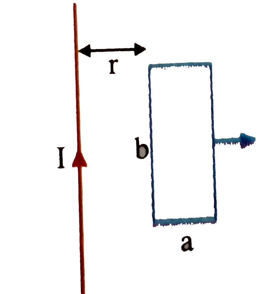
View SolutionA rectangular loop of wire with dimensions shown in figure is coplanar with a long wire carrying current `'I'`. The distance between the wire and the left side of the loop is `r`. The loop is pulled to the right as indicated. What are the directions of the induced current in the loop and the magnetic forces on the left and right sides of the loop when the loop is pulled ?
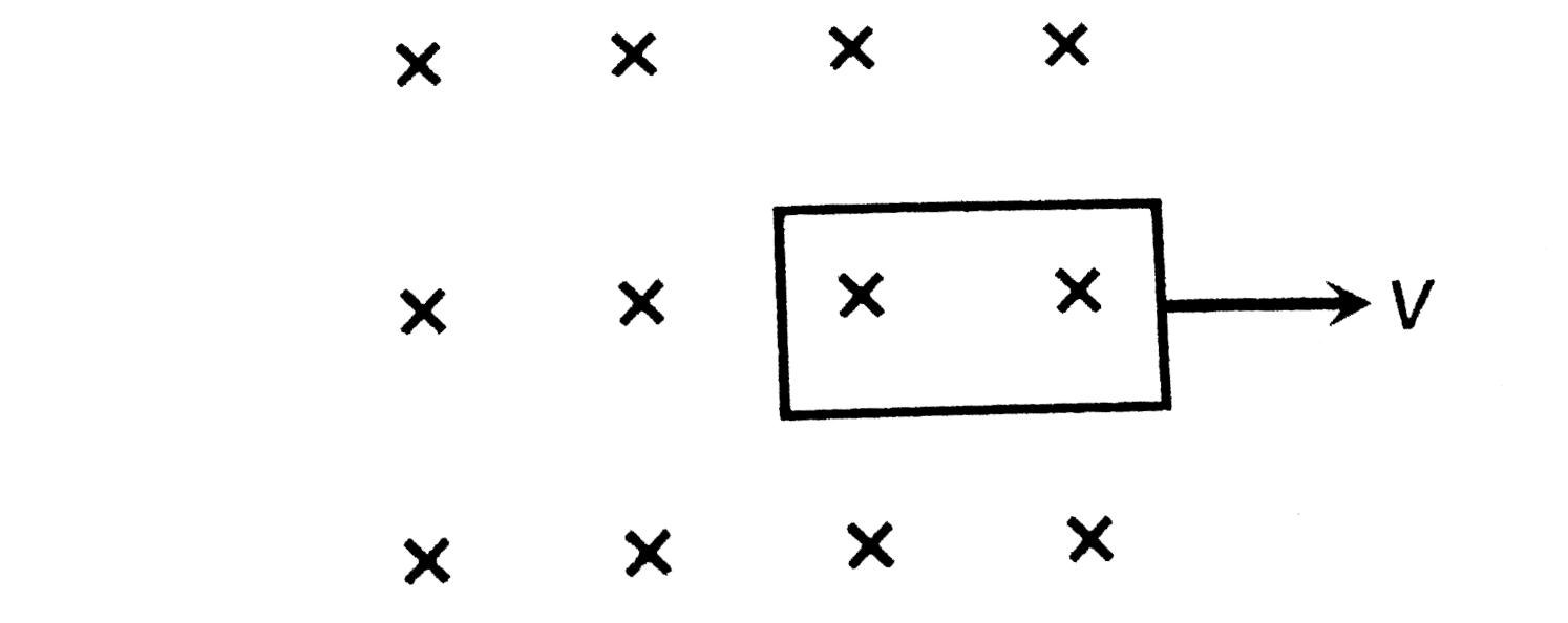
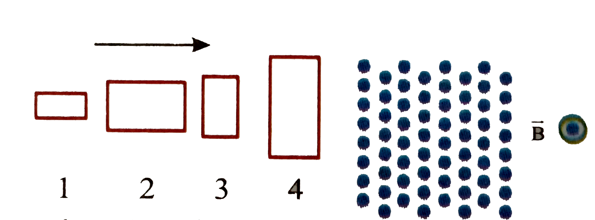
View SolutionThe four wire loops shown figure have vertical edge lengths of either `L, 2L` or `3L`. They will move with the same speed into a region of uniform magnetic field `vec(B)` directed out of the page. Rank them according to the maximum magnitude of the induced emf greatest to least.
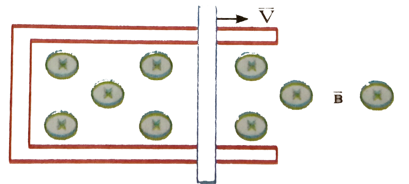
View SolutionA rod lies across frictionless rails in a uniform magnetic field `vec(B)` as shown in figure. The rod moves to the right with speed `V`. In order to make the induced emf in the circuit to be zero, the magnitude of the magnetic field should
View SolutionThe current through the coil in figure (i) varies as shown in figure (ii). Which graph best shows the ammeter `A` reading as a function of time?

View SolutionAn electron moves on a straight line path XY the path show . The abcd id coil adjacent in the path of electron . What will be the direction of current , if any induced in the coil ?

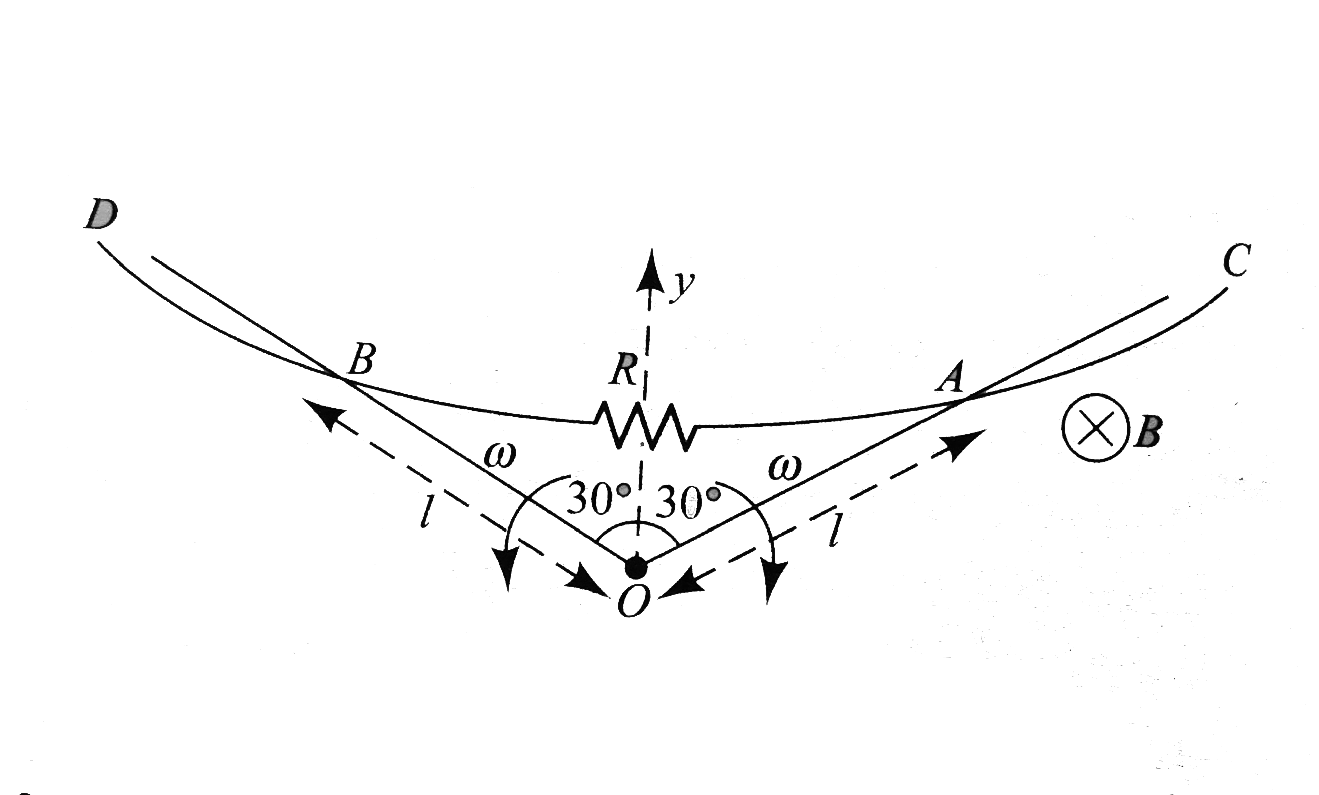
View SolutionIn fig. there exists a uniform magnetic field `B` into the plane of paper. Wire `CD` is in the shape of an arc and is fixed. `OA` and `OB` are the wires rotating with angular velocity `omega` as shown in the figure in the same plane as that of the arc about point `O`. If at some instant, `OA = OB = l` and each wire makes angle `theta = 30^(@)` with y-axis, then the current through resistance `R` is (wires `OA and OB` have no resistance)
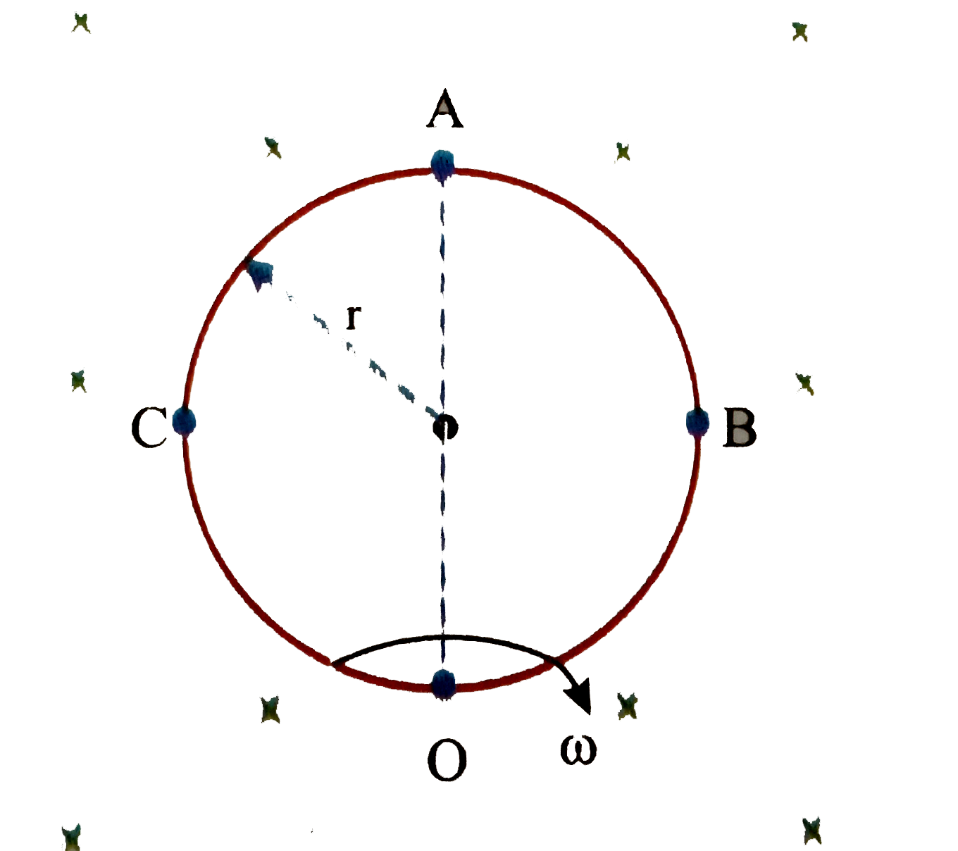
View SolutionIn figure, there is conducting ring having resistance `R` placed in the plane of paper in a uniform magnetic field `B_(0)`. If the rings is rotating in the plane of paper about an axis passing through point `O` and perpendicular to the plane of paper with constant angular speed `omega` in clockwise direction, then
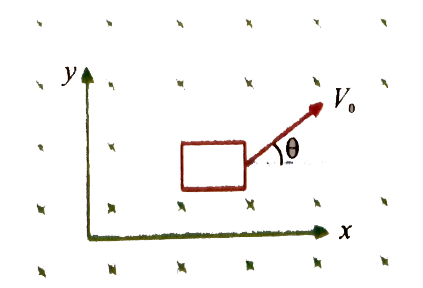
View SolutionIn the space shown a non-uniform magnetic field `vec(B) = B_(0)(1+x)(-hat(k))` tesla is present. A closed loop of small resistance, placed in the `x y` plane is given velocity `V_(0)`. The force due to magnetic field on the loop is
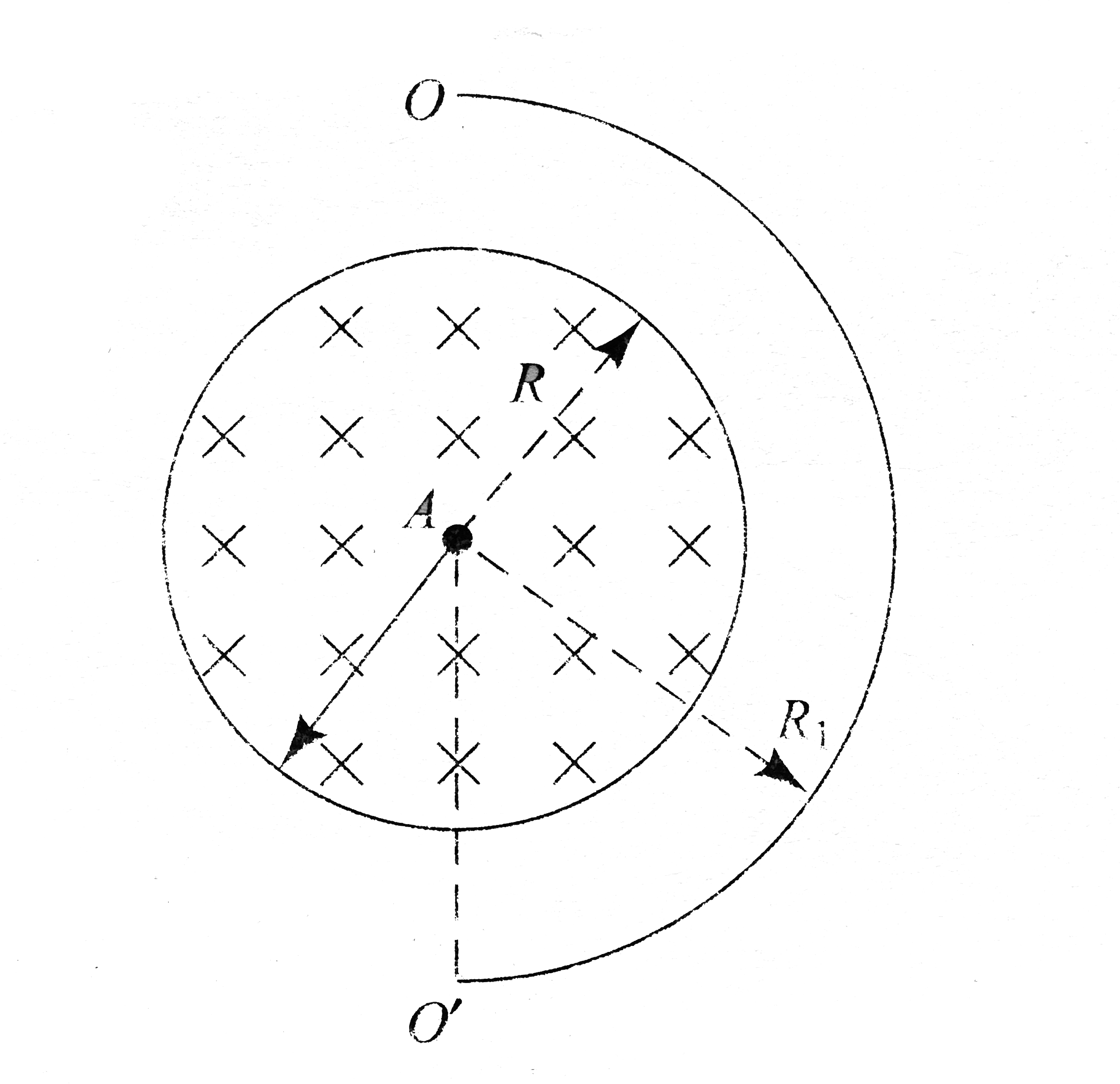
View SolutionThere is a uniform magnetic field `B` in a circular region of radius `R` as shown in Fig. 3.149 whose magnitude changes at the rate of `dB//dt`. The emf circular concentric conducting arc of radius `R_(1)` having an angle `theta` as shown `(-OAO' = theta)` is
View SolutionA gold rod of length `l` is accelerated in the horizontal direction with an accleration `a_(0)`. The rod is held between two perfactly insulating clamps. Calculate the electric field set up in the rod. Take the mass of electron as `m`.
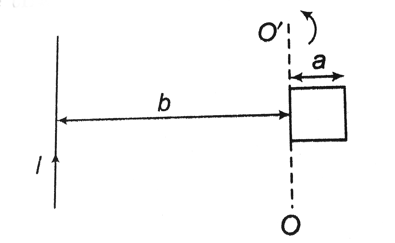
View SolutionA square loop of side as and a straight long wire are placed in the same plane as shown in figure. The loop has a resistance `R` and inductance `L`. The frame is turned through `180^@` about the axis `OO^'`. What is the electric charge that flows through the loop?
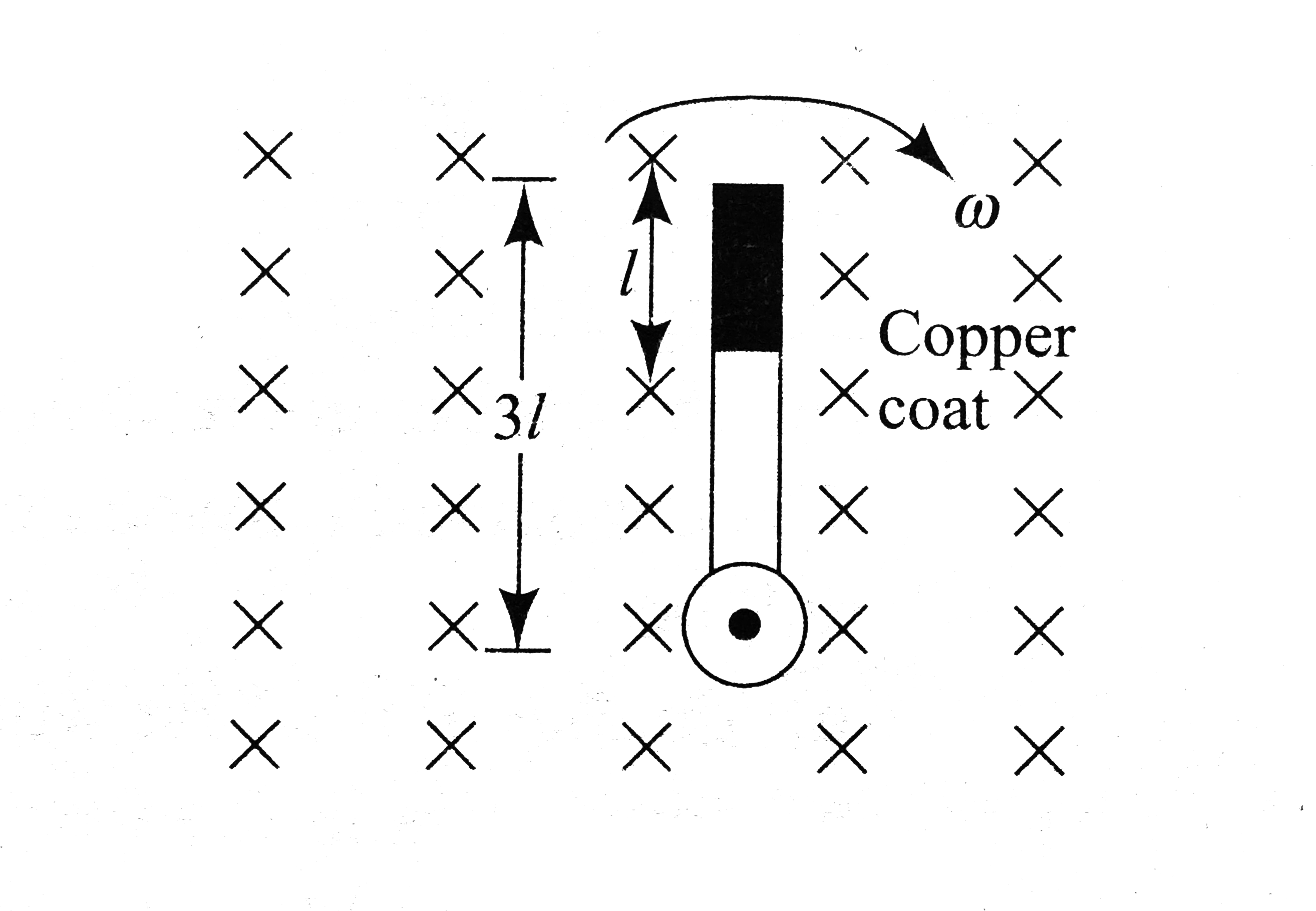
View SolutionA wooden stick of length `3l` is rotated about an end with constant angular velocity `omega` in a uniform magnetic field `B` perpendicular to the plane of motion. If the upper one-third of its length is coated with copper, the potential difference across the whole length of the stick is
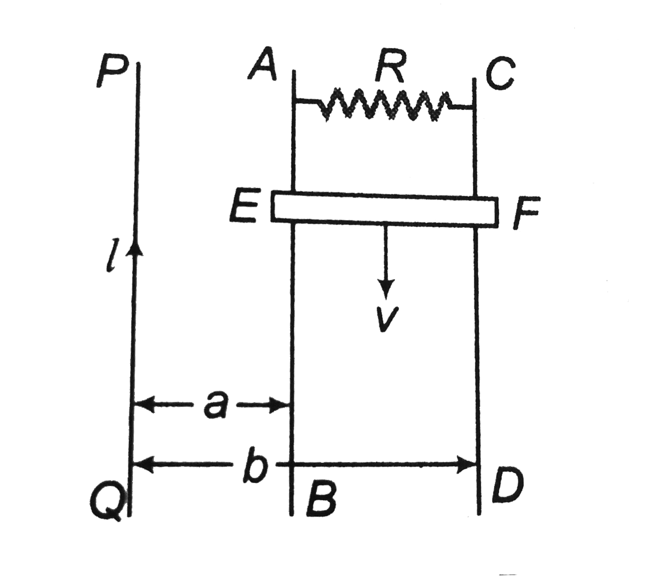
View Solution`PQ` is an infinite current carrying conductor. `AB` and `CD` are smooth conducting rods on which a conductor `EF` moves with constant velocity `v` as shown. The force needed to maintain constant speed of `EF` is
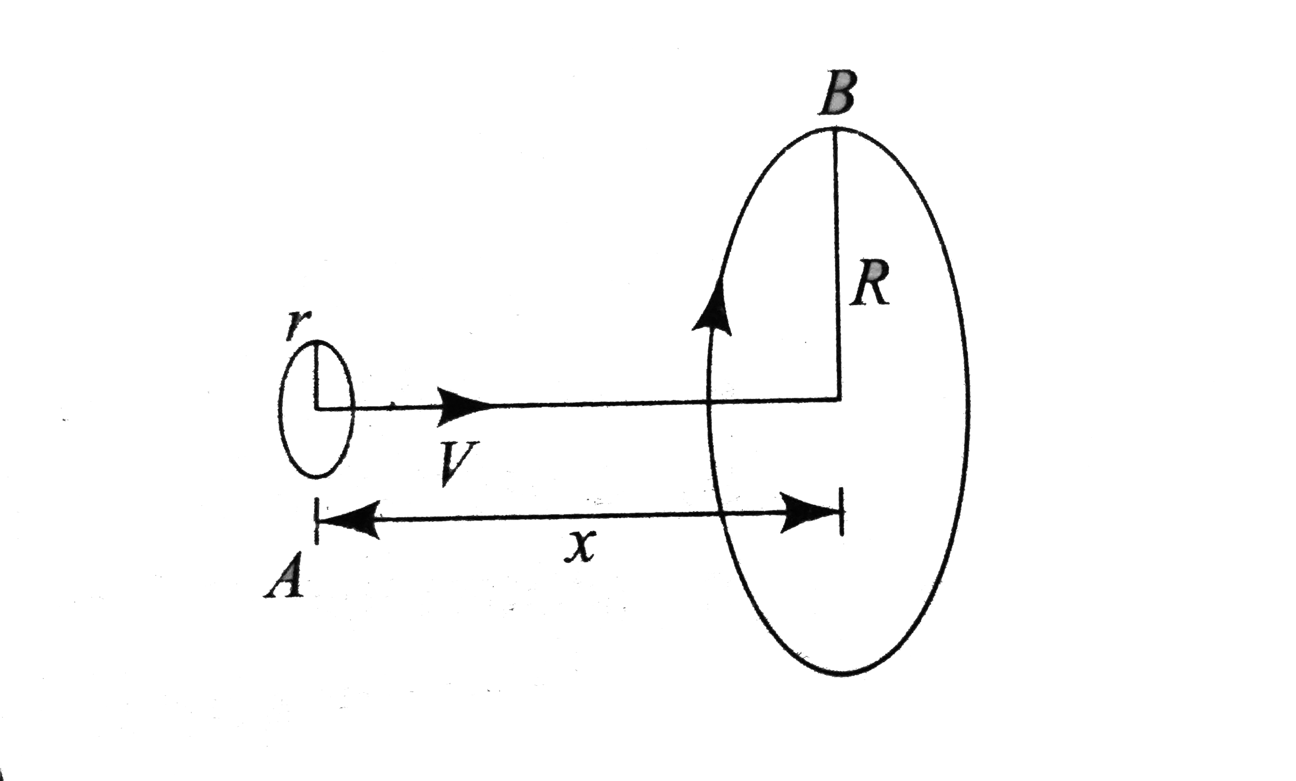
View SolutionLoop `A` of radius `rgtgtR` moves toward loop `B` with a constant velocity `V` such a way that their planes are always parallel. What is the distance between the two loops `(x)` when the induced emf in loop `A` is maximum?
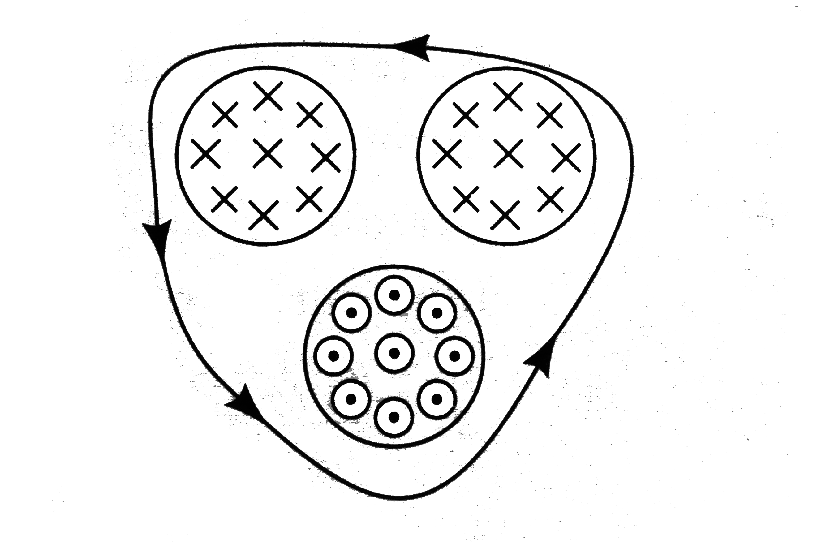
View SolutionFigure. shows three rigions of magnetic field each of area `A`, and in each rigion, magnitude of mqagnetic field decreases rate `alpha`. If `vec(E)` is the induced electric field, then the vlue of the line `ointvec(E).dvec(r )` along the given loop is equal to
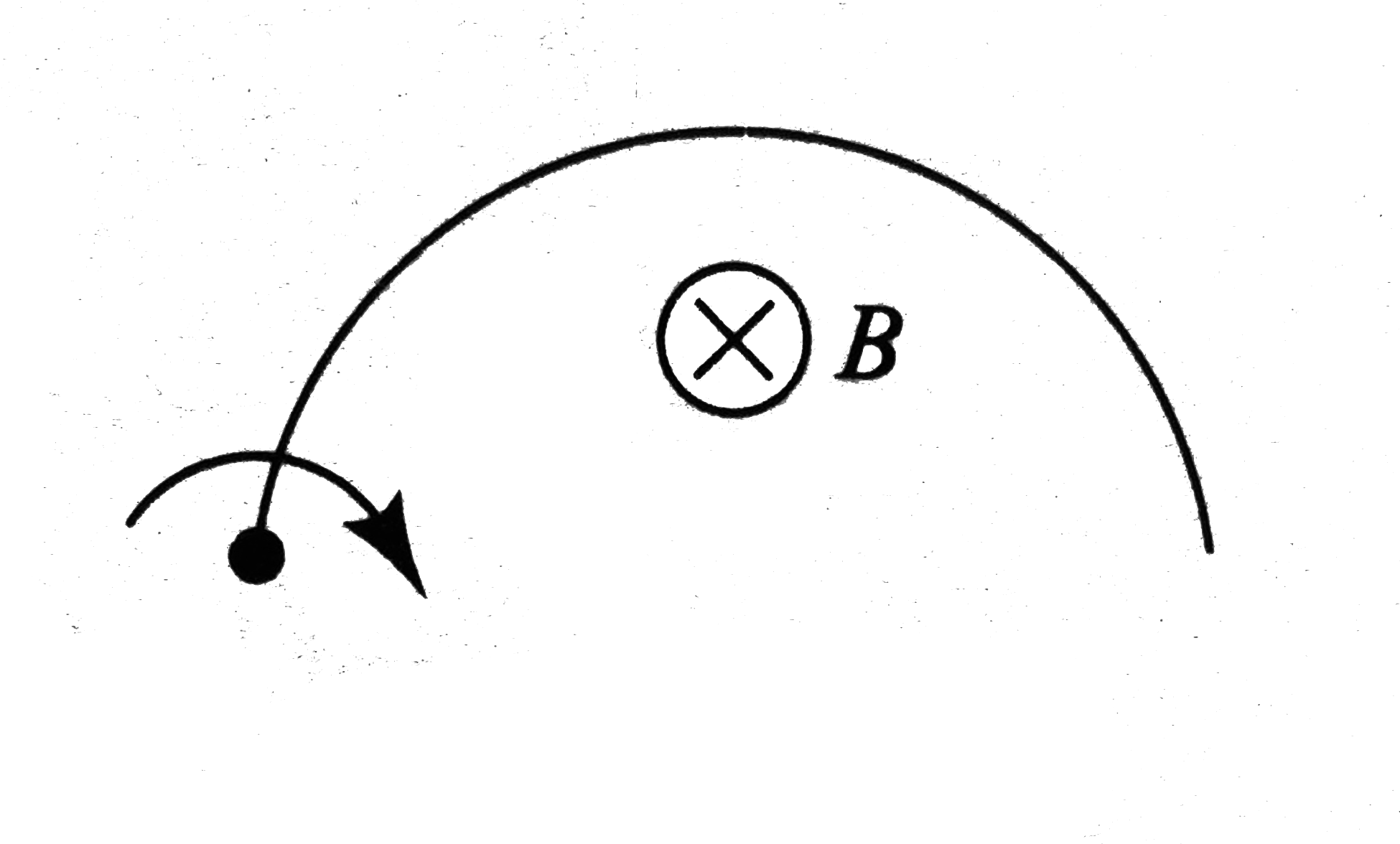
View Solutiona semicircle wire of radius `R` is rotated with constant angular velocity about an axis passing through one end and perpendicular to the plane of wire. There is a uniform magnetic field of strength `B`. The induced emf between the ends is
View SolutionTwo identical cycle wheels (geometrically have different number of spokes connected from center to rim. One if having `20` spokes and the other having only `10` (the rim and the spokes are resistance less). One resistance of value `R` is connected between centre and rim. The current in `R` will be
View SolutionA uniform magnetic field existsin region given by `vec(B) = 3 hat(i) + 4 hat(j)+5hat(k)`. A rod of length `5 m` is placed along `y`-axis is moved along `x`- axis with constant speed `1 m//sec`. Then the magnitude of induced `e.m.f` in the rod is :
View SolutionShows a square loop having 100 turns, an area of `2.5 X10^(-3) m^2` and a resistance of `100 Omega`. The magnetic field has a magnitude B =0.40 T. Find the work done in pulling the loop out of the field, slowly and uniformly is 1.0 s.
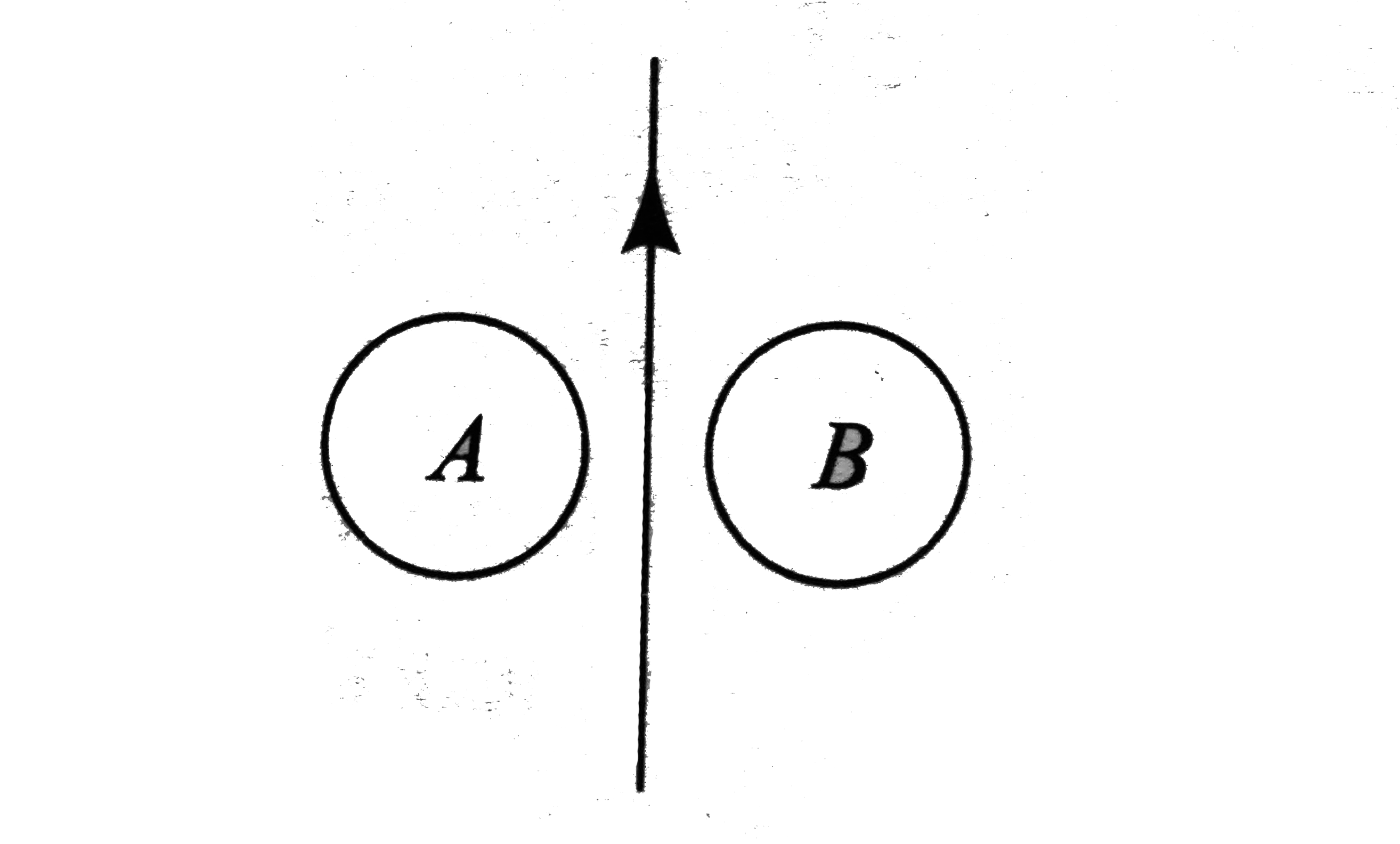
View Solution`A and B` two metallic rings pplaced at opposite sides of an infinitely long straight conducting wire as shown in Fig. 3.157. If current in the wire is slowly decreased, the direction of the induced current will be
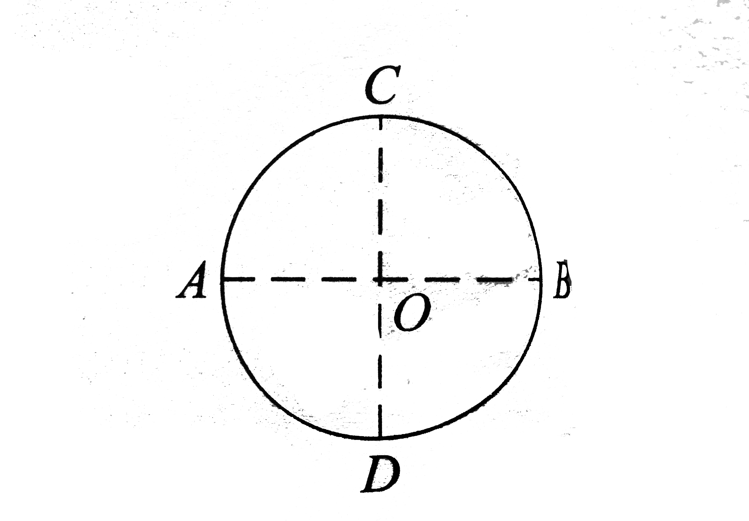
View SolutionA vertical conducting ring of radius `R` falls vertically with a speed `V` in a horizontal uniform magnetic field `B` which is perpendicular to the plane of the ring. Which of the following statements is correct?
View SolutionTwo identical conducting rings `A` and `B` of radius `R` are rolling over a horizontal conducting plane with same speed `v` but in opposite direction. A constant magnetic field `B` is present pointing into the plane of paper. Then the potential difference between the highest points of the two rings is

View SolutionAn inducatane L and a resistance R are connected in series with a battery of emf epsilon. Find the maximum rate at which the energy is stored in the magnetic field.
View SolutionA uniform magnetic field of induction B is confined to a cylindriacal region of radius R. The magnetic field is increasing at a constant rate of `(Db)/(dt)). Am electron of charge e, placed at the point P on the preriphery of the field experiences accceleration.
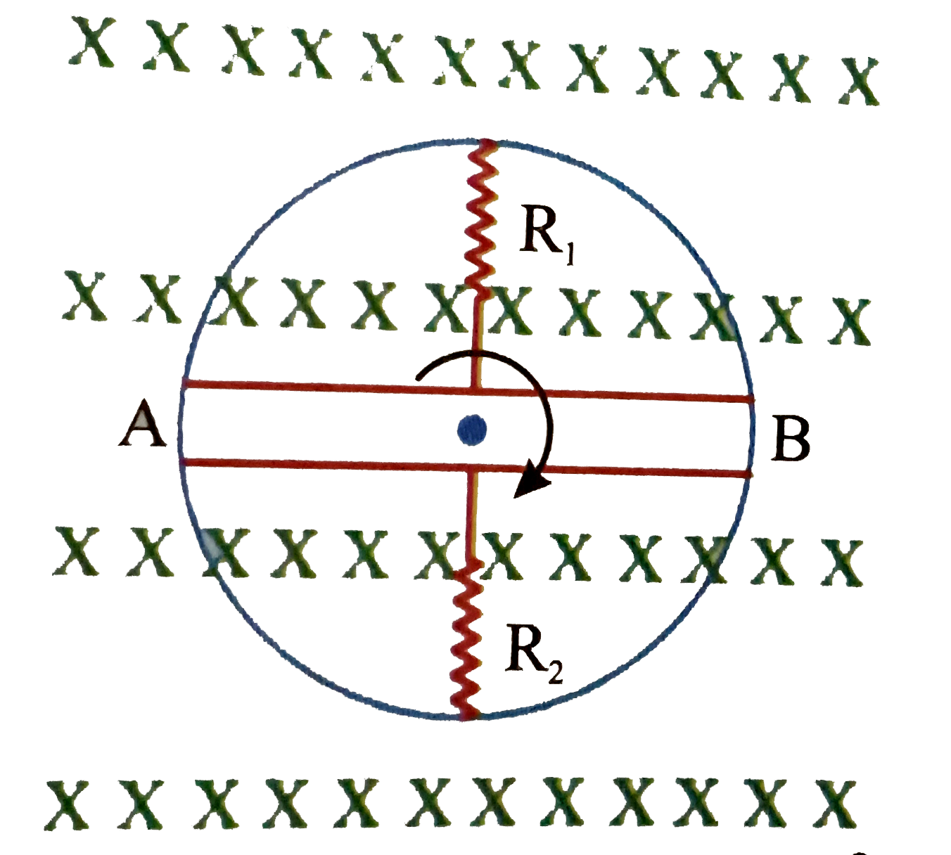
View Solution`AB` is a resistanceless conducting rod which forms a diameter of a conducting ring of radius `r` rotating in a uniform magnetic field `B` as shown in figure. The resistance `R_(1)` and `R_(2)` do not rotate. Then the current through the resistor `R_(1)` is
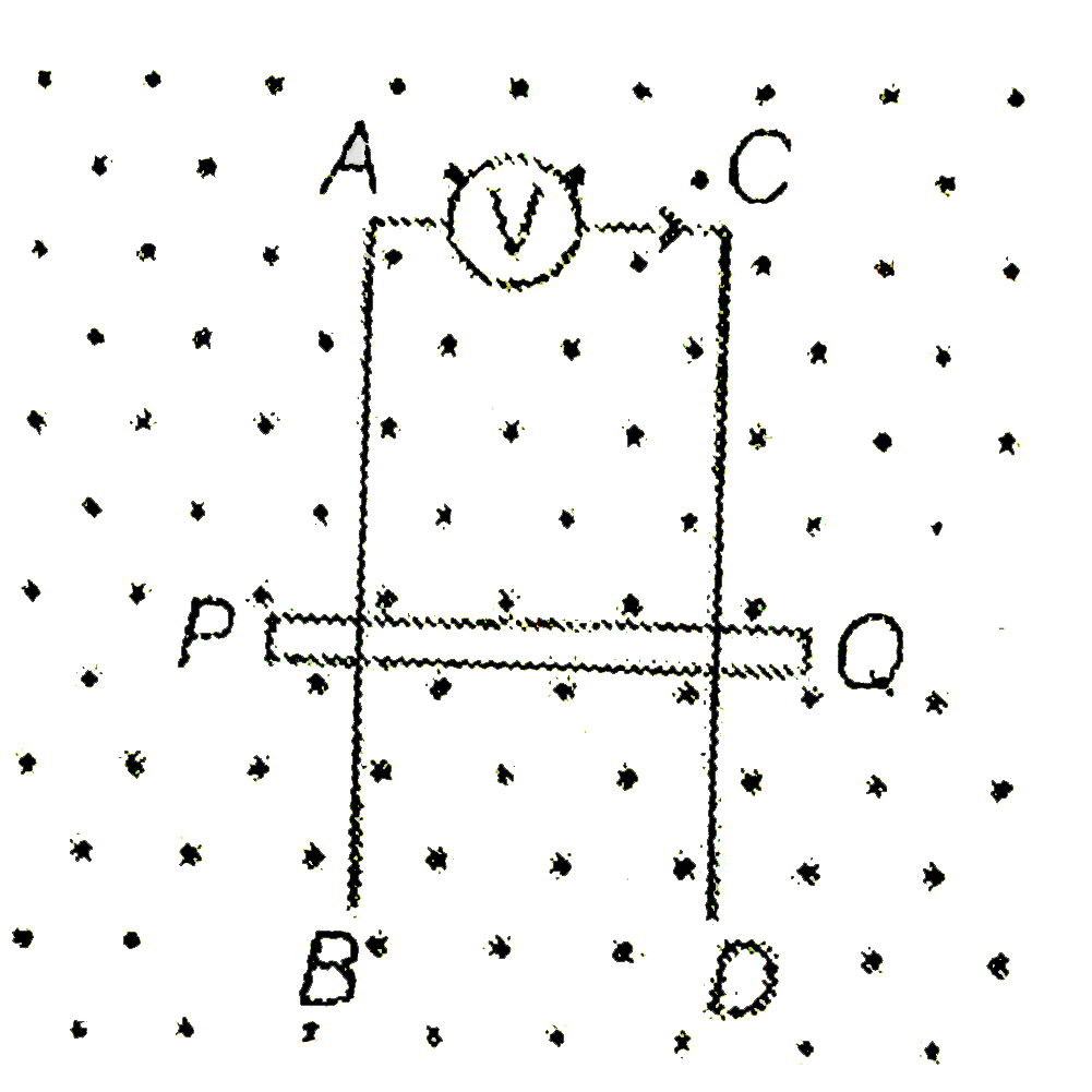
View SolutionAB and CD are fixed conducting smooth rails plaed in a vertical plane and joined by a constant current source at tits upper end PQ is a conducting rod which is freee to slide on the rails. A horizontal uniform magnetic field exiets in space as shown. If the rod PQ is released from rest then,
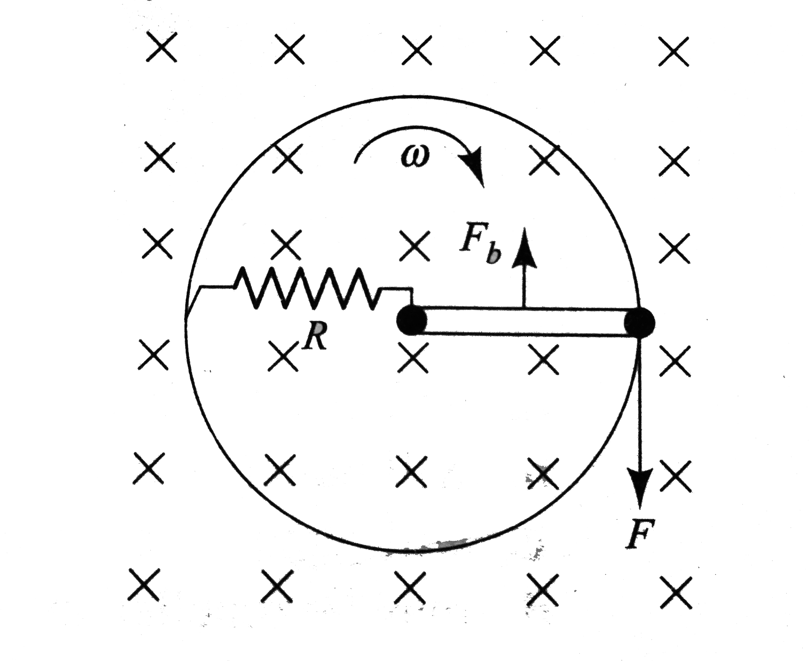
View SolutionA metallic ring of radius `r` with a uniform metallic spoke of negligible mass and length `r` is rotated about its axis with angular velocity `omega` in a perpendicular uniform magnetic field `B` as shown in Fig. 3.163. The central end of the spoke is connected to the rim of the wheel through a resistor `R` as shown. The resistor does not rotate, its one end is always at the center of the ring and the other end is always in as shown is needed to maintain constant angular velocity of the wheel. `F` is equal to (the ring and the spoke has zero resistance)
View SolutionThe current generator `i_g`, shown in , sends a constant current I through the circuit. The wire ab has a length l and mass m and can slide on the smooth, horizontal rails connected to `l_g`. The entire system lies in a vertical magnetic field B. Find velocity of the wire as a function of time.
(##HCV_VOL2_C38_E01_081_Q01##)
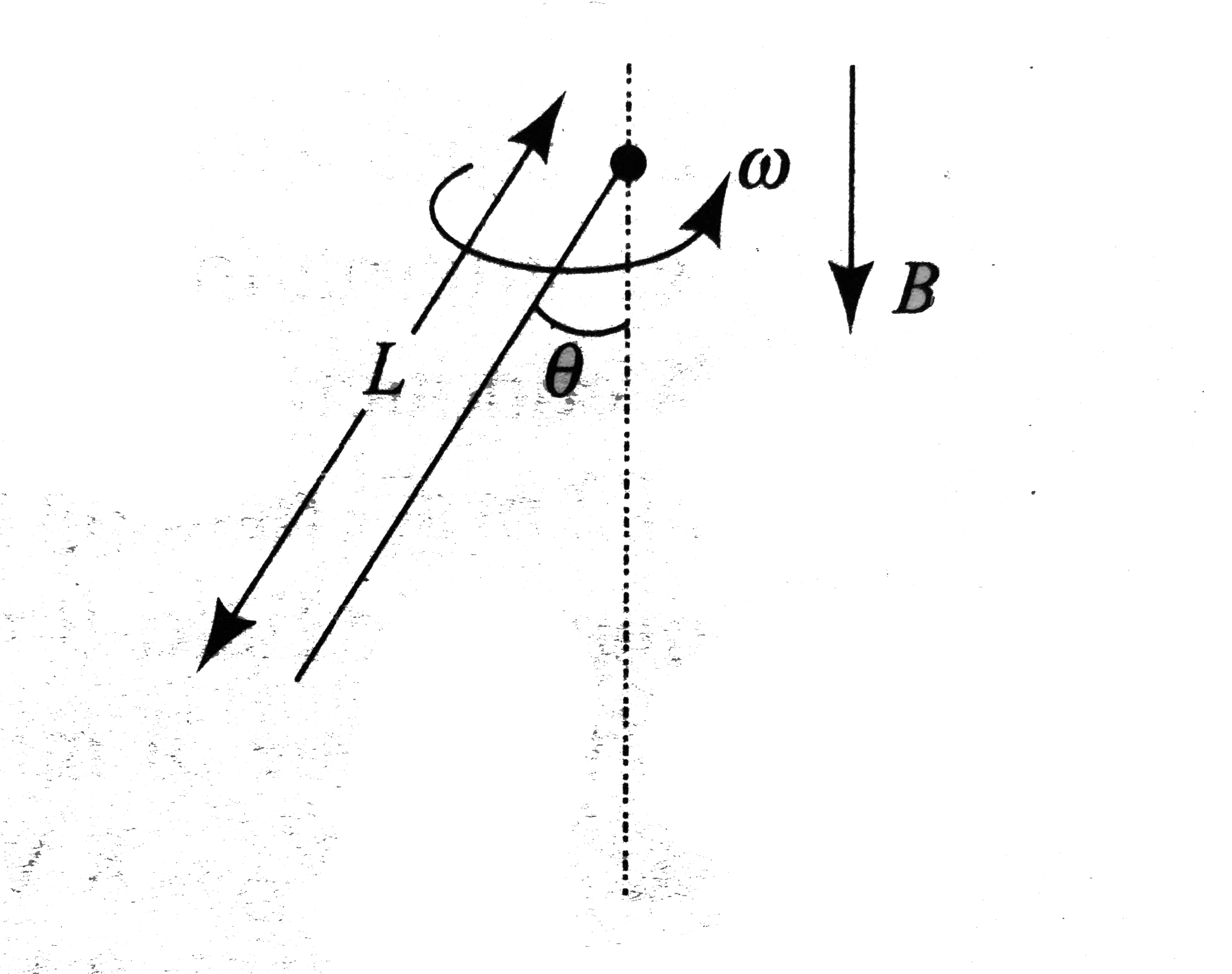
View SolutionA rod of length `L` rotates in the form of a conical pendulum with an Angular velocity `omega ` about its axis as shown in Fig. 3.165. The rod makes an angle `theta` with the axis. The magnitude of the motional emf developed across the two emf of the rod is
View SolutionA magnetic field induction is changing in magnitude in a region at a constant rate `dB//dt`. A given mass `m` of copper drawn into a wire and formed into a loop is placed perpendicular to the field. If the values of specific resistance and density of copper are `rho` and `sigma` respectively, then the current in the loop is given by :
View SolutionThe magnetic field existing in a region is given by `vecB =B_0(1+(x)/(l))vec k.` A square loop of edge l and carrying a current I, is placed with its edges parallel to the x-y axes. Find the magnitude of the net magnetic force experienced by the loop.
View SolutionA conductor `AB` of length `l` moves in `x y` plane with velocity `vec(v) = v_(0)(hat(i)-hat(j))`. A magnetic field `vec(B) = B_(0) (hat(i) + hat(j))` exists in the region. The induced emf is
View SolutionA line charge `lambda` per unit length is pasted uniformly on to the wire of a wheel of mass `m` and radius `R`. The wheel has light non-conducting spokes and is free to rotate about a vertical axis as shown in `Fig. 3.166`. A uniform magnetic field extends over a radial rigion of radius `r` given by `B = -B_(0)hat(k)(r le a, alt R) = 0` (otherwise). What is the angular velocity of the wheel this field is suddenly switched off?
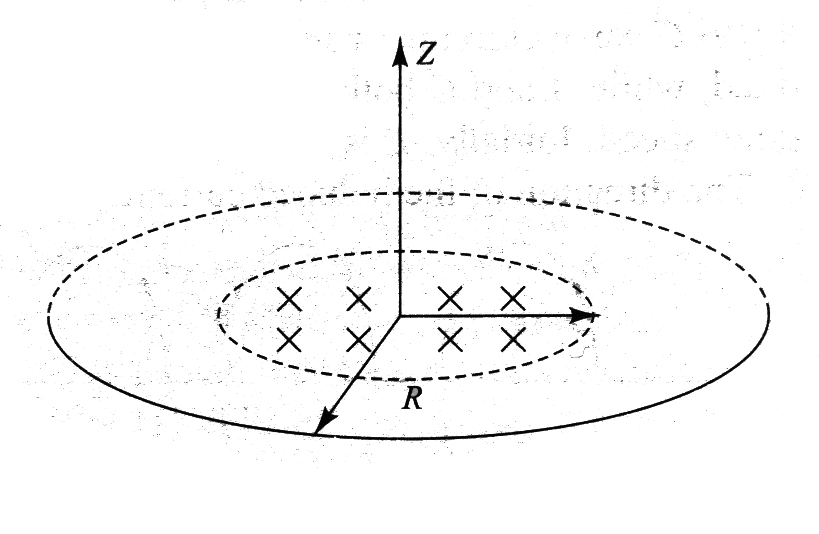
View SolutionA flexible wire loop in the shape of a circle has a radius that grows linearly with time. There is a magnetic field perpendicular to the plane of the loop that has a magnitude inversely proportional to the distance from the centre of the loop, `B(r ) prop (1)/(r )` How does the `emf` `E` vary with time?
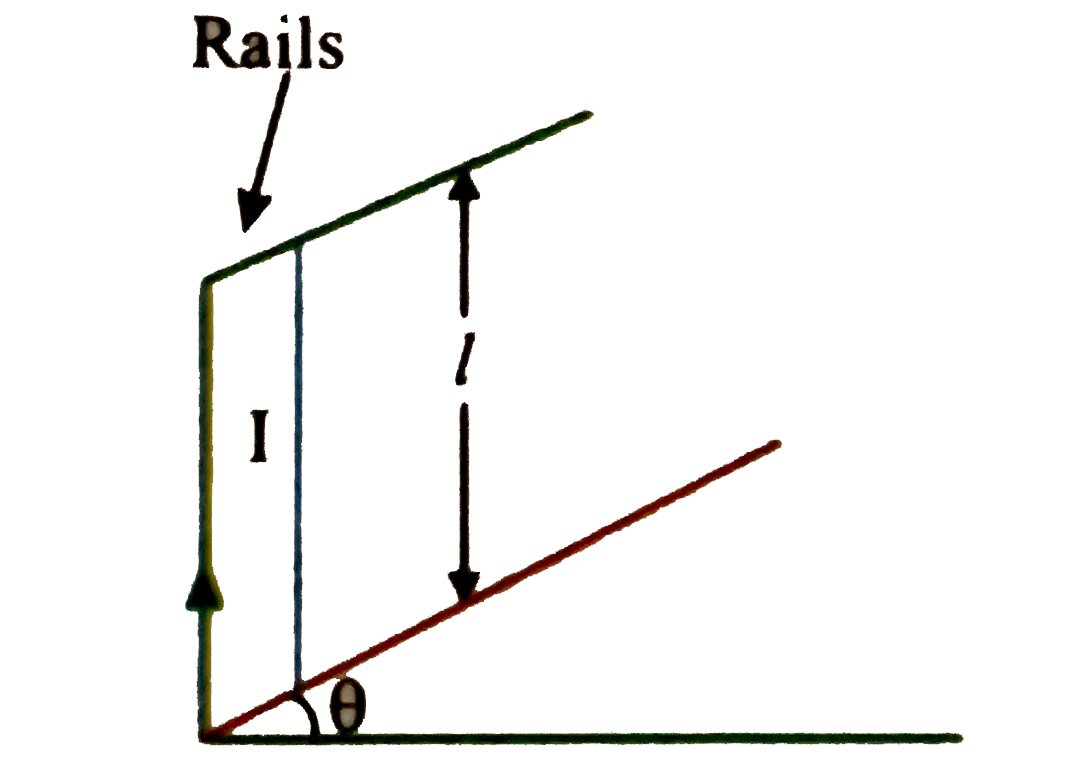
View SolutionA conducting wire of length `l` and mass `m` is placed on two inclined rails as shown in figure. A current `I` is flowig in the wire in the direction shown When no magnetic field is present in the region, the wire is just on the verge of sliding. When a vertically upward magnetic field is switched on, the wire starts moving up the incline. The distance travelled by the wire as a function of time `t` will be
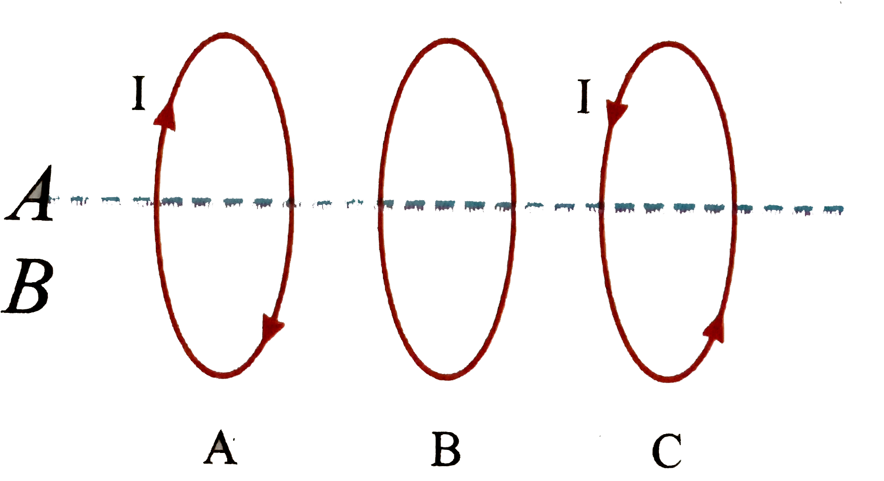
View SolutionThree identical coils `A,B` and `C` carrying currents are placed co-axially with their planes parallel to one another. `A` and `C` carry current as shown in figure `B` is kept fixed while `A` and `C` both are moved towards `B` with the same speed. Initially, `B` is equally separated from `A` and `C`. The direction of the induced current in the coil `B` is
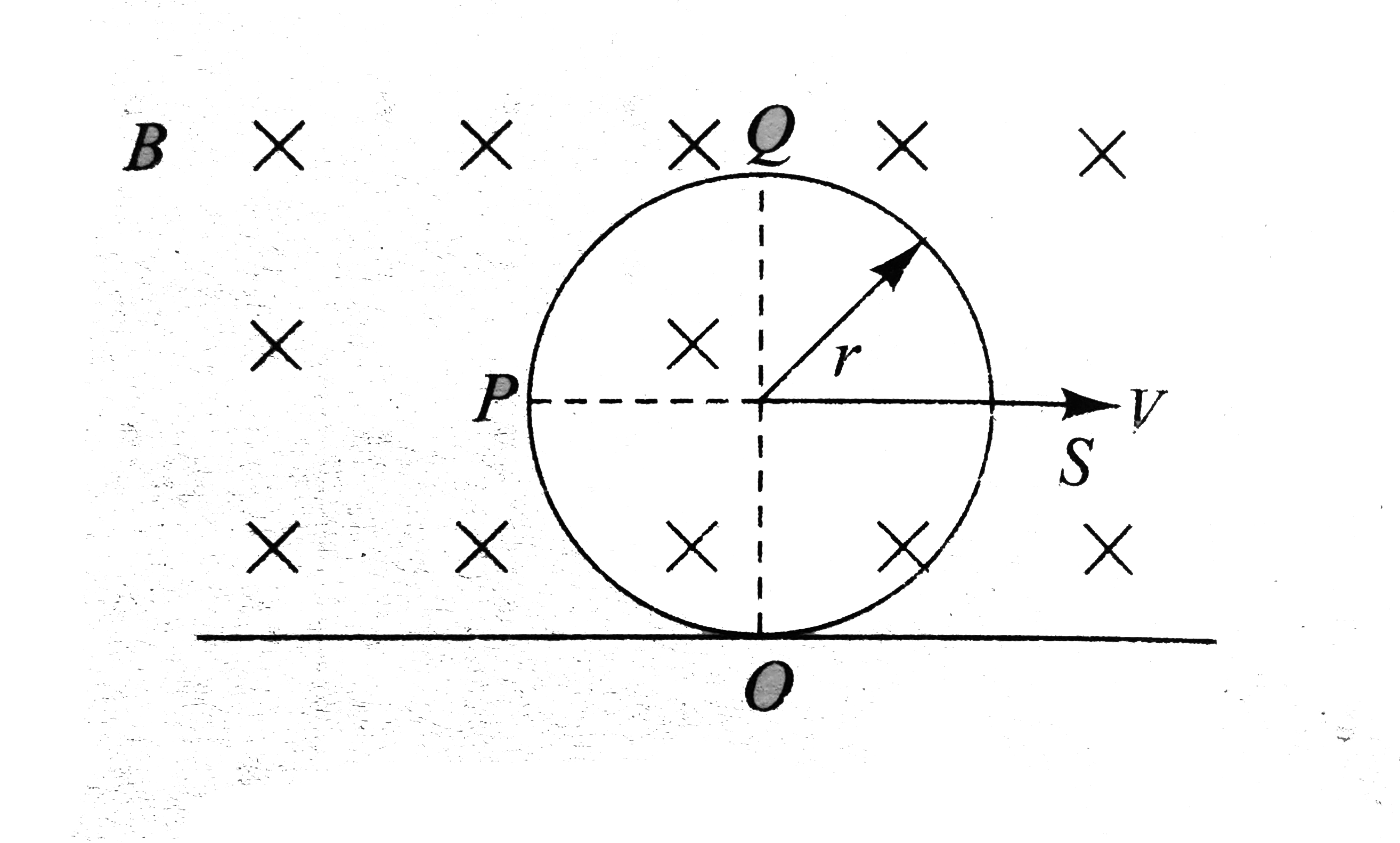
View SolutionA conducting ring of radius `r` and resistance `R` rolls on a horizintal surface with constant velocity `v`. The magnetic field `B` is uniform and is normal to the plane of the loop. Choose the correct option.
View SolutionTwo identical conductors P and Q are placed on two frictionless rails R and S in a uniform magnetic field directed into the plane. If P is moved in the direction shown in figure with a constant speed then rod Q
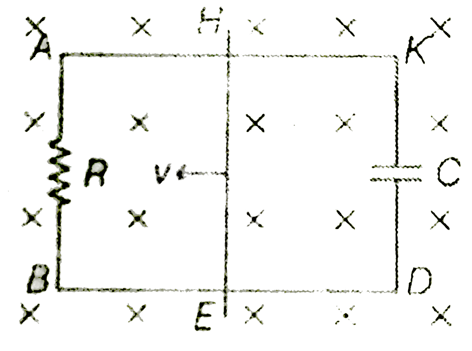
View SolutionIn the circuit shown in figure, a conducing wire HE is moved with a constant sped v towards left. The complete circuit is placed in a uniform magnetic field B perpendicular to the plane of circuit inwards. The current in HKDE is
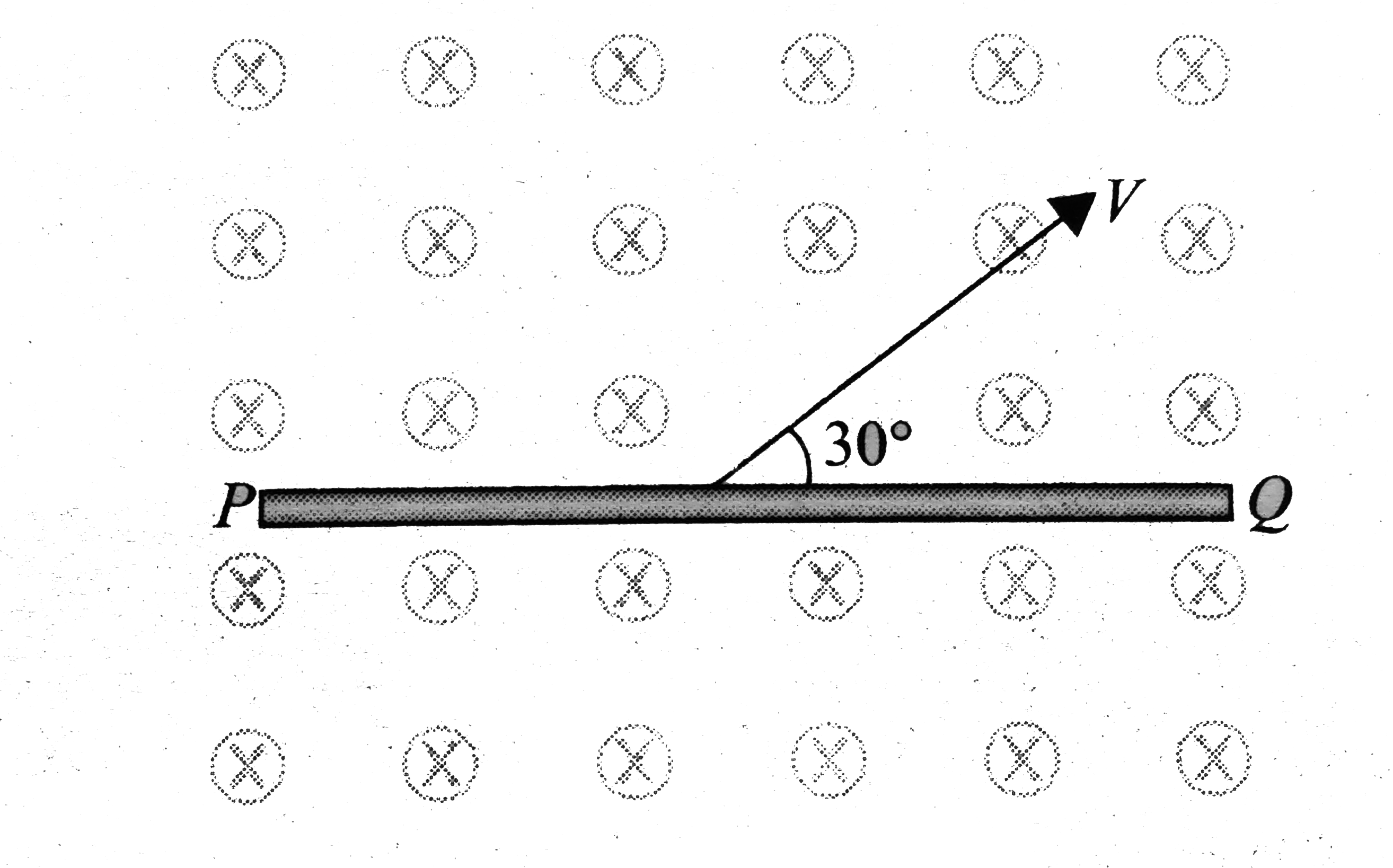
View SolutionA conducting rod `PQ` of length `l = 2m` is moving at a speed of `2m s^(-1)` making an angle of `30^(@)` with its length. A uniform magnetic field `B = 2T` exists in a direction perpendicular to the plane of motin. Then
View SolutionA mentallic wire is folded to from a square loop of a . It crries a cureent i and is kept perpendicular to unifrom magnetic field . If the shape of the loop changed from squre to a circle without changing length of the wire and current, the amount of wire done in doing so is
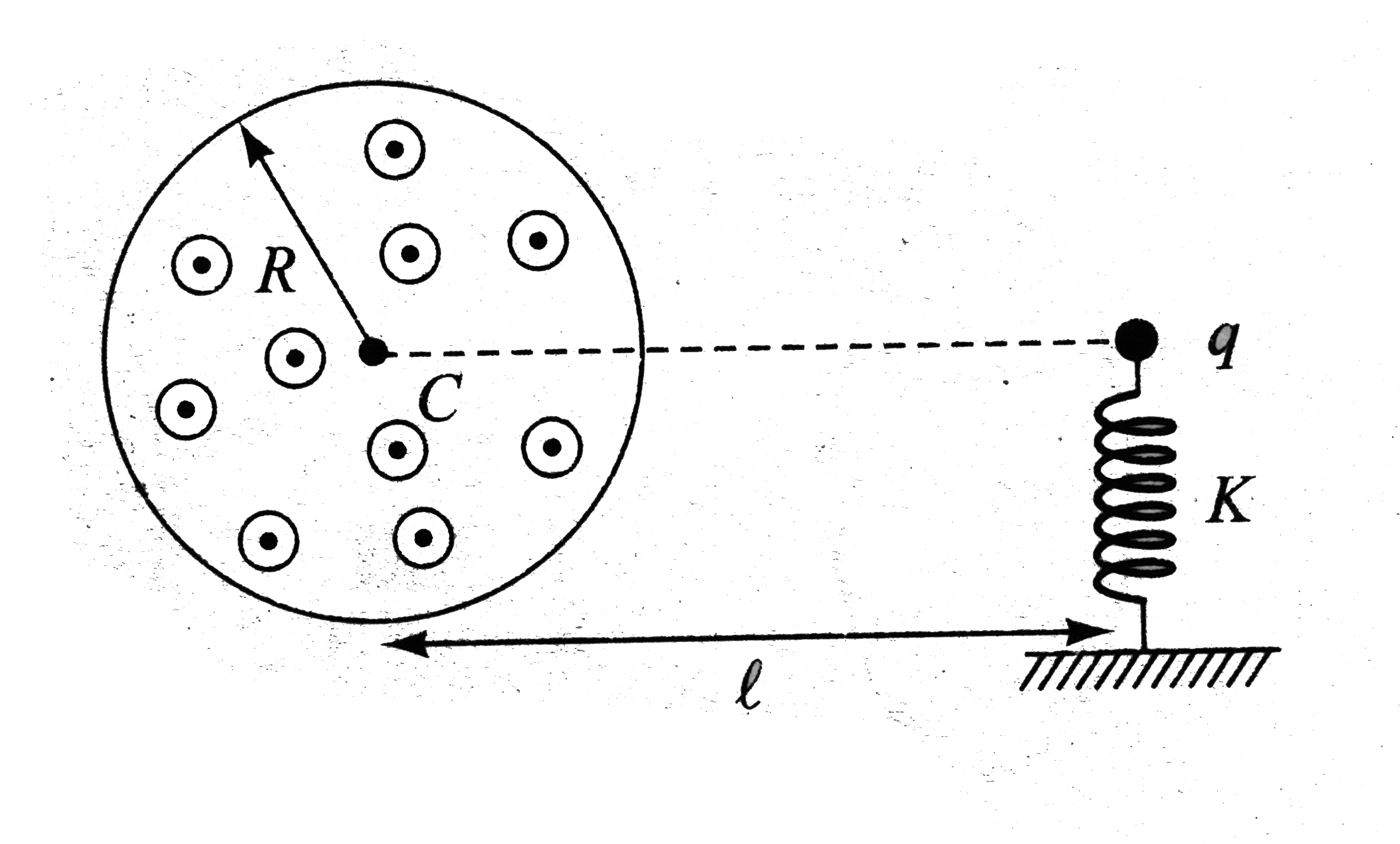
View SolutionThere is a horizontal cylindrical uniform but time-varying nagnetic field increasing at a constant rate `dB//dt` as shown in Fig. 3.173. A charged particle having charge `q` and mass `m` is kept in euilibrium, at the top of a spring of spring constant `K`, in such a way that it is on the horizontal line passing through the center of the magnetic field as shown in the figure. The compression in the spring will be
View Solution
Exercises Single Correct questions and complete solutions for chapter ELECTROMAGNETIC INDUCTION of CENGAGE PHYSICS (ENGLISH) of Class 12
All Exercises from CENGAGE PHYSICS Class 12 PHYSICS ELECTROMAGNETIC INDUCTION
- Archives Asserton - Reasoning
- Archives Fill In The Blanks
- Archives Multiple Correct
- Archives Single Correct
- comprehensive
- comprehensive type
- compression type
- Exercise 3.1
- Exercise 3.2
- Exercises Asserton - Reasoning
- Exercises Integer
- Exercises Linked Comprehension
- Exercises Multiple Correct
- Exercises Single Correct
- Exercises Subjective
- Illustration
- Multiple correct Answer Type
- single correct
- single correct
- single correct answer
- Single Correct Answer Type
- Solved Example