Complete Solutions to Exercise 4.2 of chapter CAPACITOR AND CAPACITANCE of Class 12 book with complete answers and questions
| Class 12 | PHYSICS |
| Chapter | CAPACITOR AND CAPACITANCE |
| CENGAGE PHYSICS | Exercise 4.2 |
| Number Of Questions | 32 |
| Academic Year | 2023-24 |
A conductor is an extreme case of a dielectric, because if an electric field is applied to a conductor, charges are free to move within the conductor to set up ''induced charges''. What is the dielectric constant of a perfect conductor? Is it `K=0,Krarroo`, or something in between ? Explain your reasoning.
View SolutionA capacitor of capacitance `C` is charged to a potential differece `V_(0)`. The terminals of the charged capacitor are then connected to those of an uncharged capacitor of capacitance `C//2`.
a. Compute the original charge of the system.
b. Find the final potential differce across each capacitor.
c. Find the final energy of the system.
d. Calculate the decrease in energy when the capacitors are connected.
e. Where did the ''lost'' energy go?
View SolutionA parallel plate vacuum capacitor eith plate area A and separation x has charges`+Q` and `-Q` on its plates. The capacitor is disconnected from the source of charge, so the charge on each plate remains fixed.
a. What is the total energy stored in the capacitor?
b. The plates are pulled apart an additional distance each case.
c. If F is the force with which the plates attract each other, the change in the stored energy must equal the work `dW =F dx` done in pulling the plates apart. Find an expression for F
d. Energy storage in a capacitor can be limited by the maximum electric field between the plates. What is the ratio of the electric field for the series for parallel combinations?
View SolutionYou have two identical capacitors and an extermal potential source.
a. Compare the total energy stored in capaciton when they are connected to the applied potential in series and in parallel.
b. Compare the maximum amount of charge stored in each case.
c. Energy storage in a capacitor can be limited by the maximum electric field between the plates. What is the ratio of the electric field for the series for parallel combinations?
View SolutionA circuit has section AB as shown in The emf of the cell is `10 V`, and the capacitors have capacitances `C_(1)=1 muF` and `C_(2)=2 muF`.
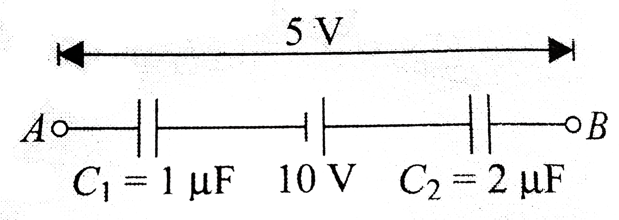 .
.
View SolutionWhile a capacitor remains connected to a battery a dielectric slab is slipped between the plates. Describe qualitatively what happens to the charge, the capacitance, the stored energy. Is work required to insert the slab?
View SolutionIf you have several `2.0 muF` capacitrors, each capable of withstanding `200 V` without breakdown, how would you assemble a combination that has an equivalent capacitance of
a. `0.4muF`
b. `1.2 muF` each with standing `1000V`?
View Solution`n` identical capacitors are connected in parallel to a potential difference `V`. These capacitors are then reconnected in sereis, their charges being left undisturbed. The potential difference obtained is
View SolutionIn the arrangement shwn in Fig.4.96, plate (B) given a charge equal to `60`
`muC`, The ratio `d_(1)//d_(2)` is 2. Then
`q_(1)="___"`
`q_(2)="_____"`
`q_(3)="_____"`
`q_(4)="______"`
`q_(5)="_______"`
`q_(6)="_______"`
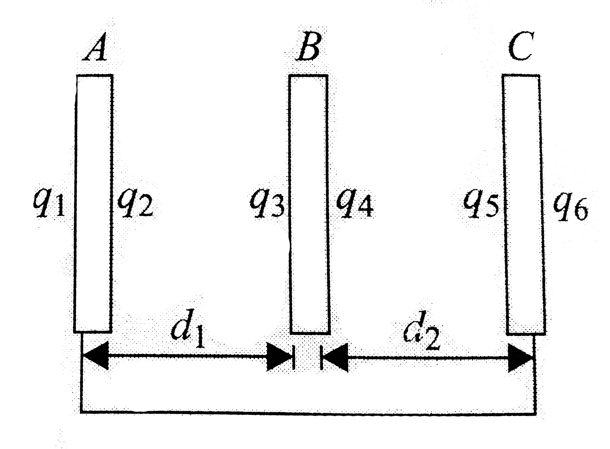 .
.
View SolutionIn plate `A` has `100 muC`
charge, while plate B has `60 muC` charge.
a. When both switches are open, then
`q_(1)="_____"`
`q_(2)="______"`
`q_(3)="______"`
`q_(4)="_______"`
b. When switch `S_(1)` is closed,
the
`q_(1)="_____"` , `q_(2)="______"`
`q_(3)="_______"` , `q_(4)="_____"`
c. When switch `S_(1)` is also closed, then
`q_(1)="______"`
`q_(2)="______"`
`q_(3)="______"` ltbrlt `q_(4)="_______"` .
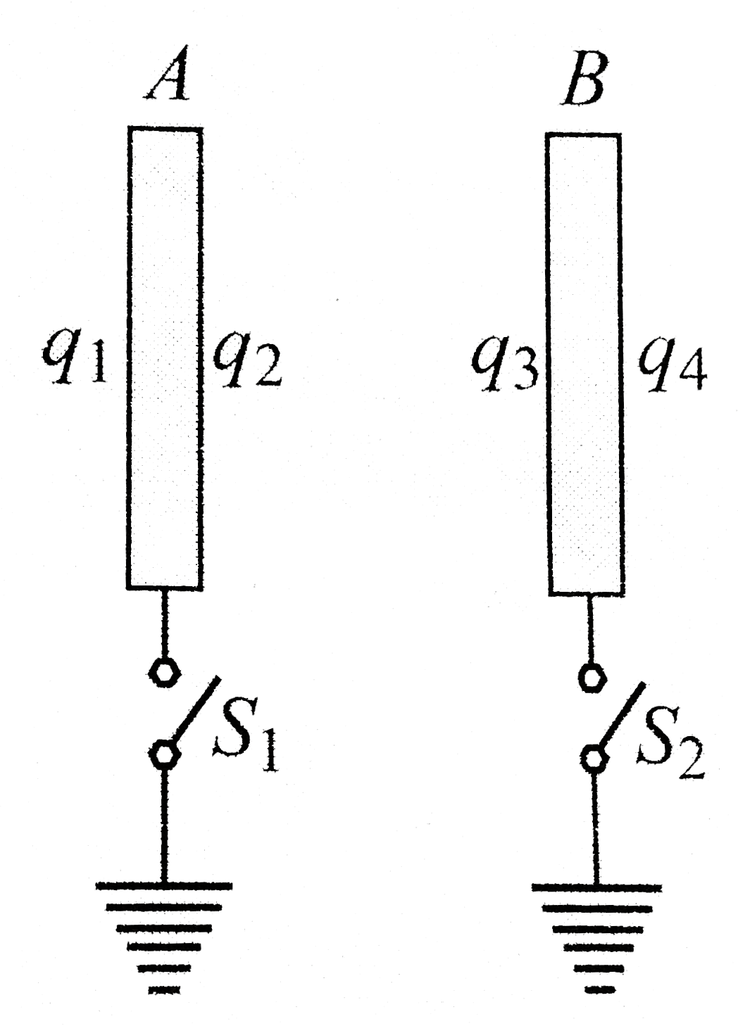 .
.
View SolutionFor the network of capacirors as shown in.
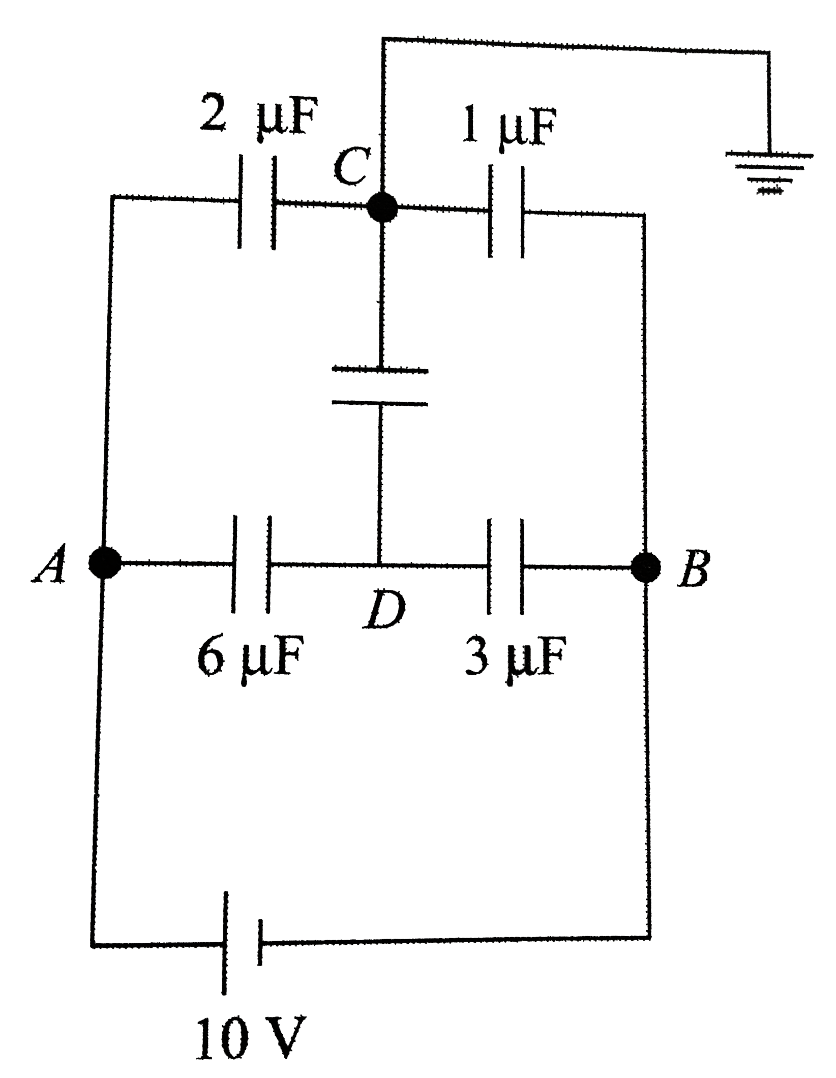 .
.
a. Find the potential of junction `D`.
b. Find the potential of function D,
c. Find the charge on `2 muF` capacitor.
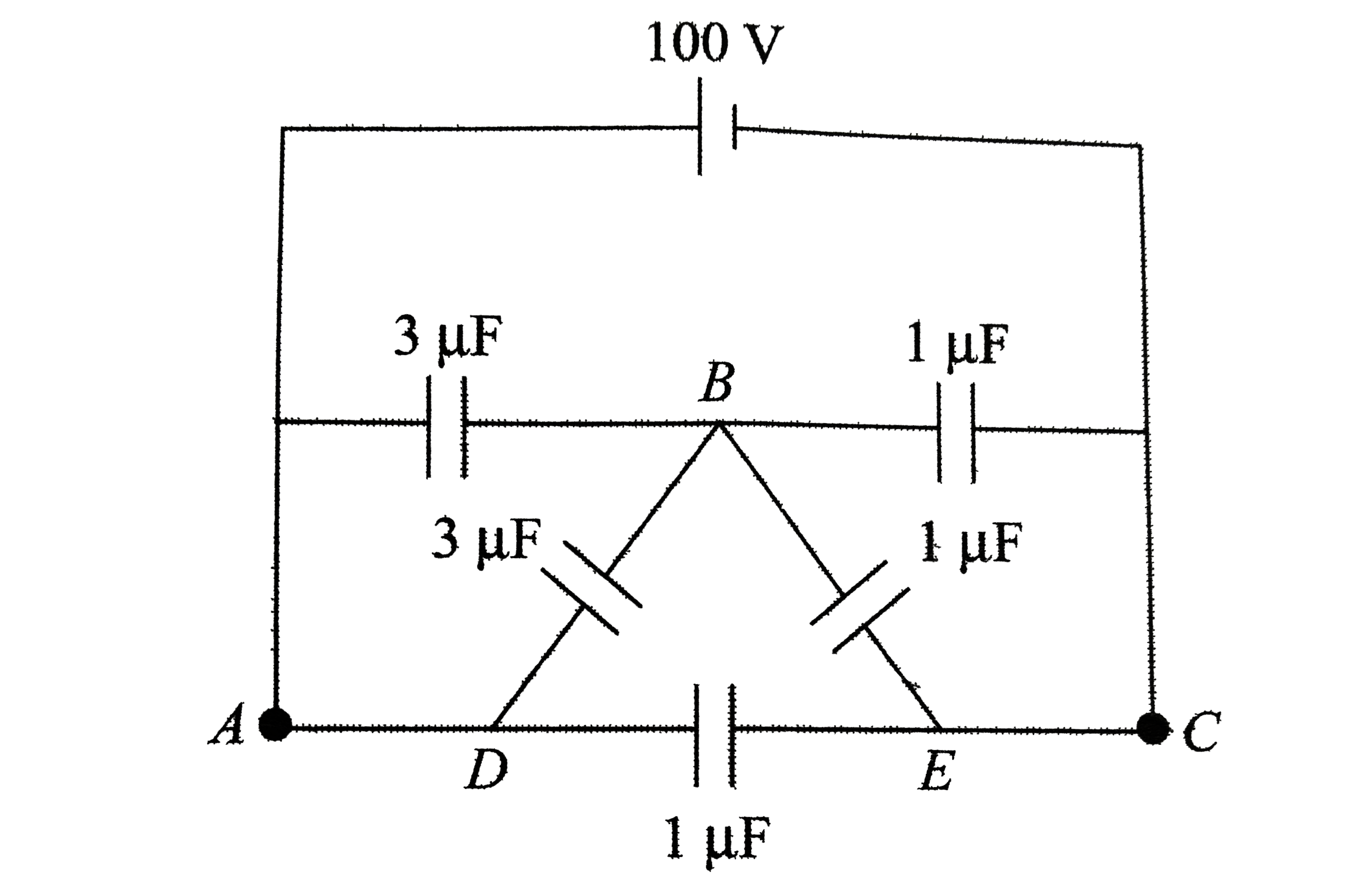
View SolutionIn the system is in steady state. Then
a. `V_(A)-V_(B)="_______"`
b. `V_(B)-V_(C)="______"`
c. `V_(D)-V_(e)="______"`
d. The energy stored in the circuit is "________"`
 .
.
View SolutionFind whether the following statements are true or false.
a. If a battery is connected across a circuit consisting of two identical capacitors, it is found that, in steady state, the two capacitors must be in series with each other.
b. If a battry is connected across a ciruit consisting of two capacitors having differnt capacitances, it is found that, in steady state, the two capacitors has equal charge, then two capacitors must be in seties with each other.
c. If a battery is connected across a circuit cansisting of two identical capacitors, it is found that, in steady state, the two capacitors have equal charge, then the two capacitors may be in series with each other.
View SolutionFind the equicalent capacitance between points `A and B` as show in
 .
.
View SolutionThree capacitors `C_(1),C_(2)` and `C_(3)` are connected as shown in, The potentials of `P,Q`, and `R` are `V_(1),V_(2),` and `V_(3)`, respectively. Find the potential `V_(0)` at the function`O`.
 .
.
View SolutionFind the charge supplied by the battery in the arrangement as shown in.
 .
.
View SolutionTwo large parallel metal plates, each having area A`, are oriented horizontally and separated by a distance `3d`. A grounded conducting wire joins them, and initially each plate carries no chatege. Now a thirdidentical plate carrying charge `Q` is inserted between the two plates, parallel to them and lacated a distance (d) from the upper plate, as shown in. What induced charge appears on each of the two original plates?
 .
.
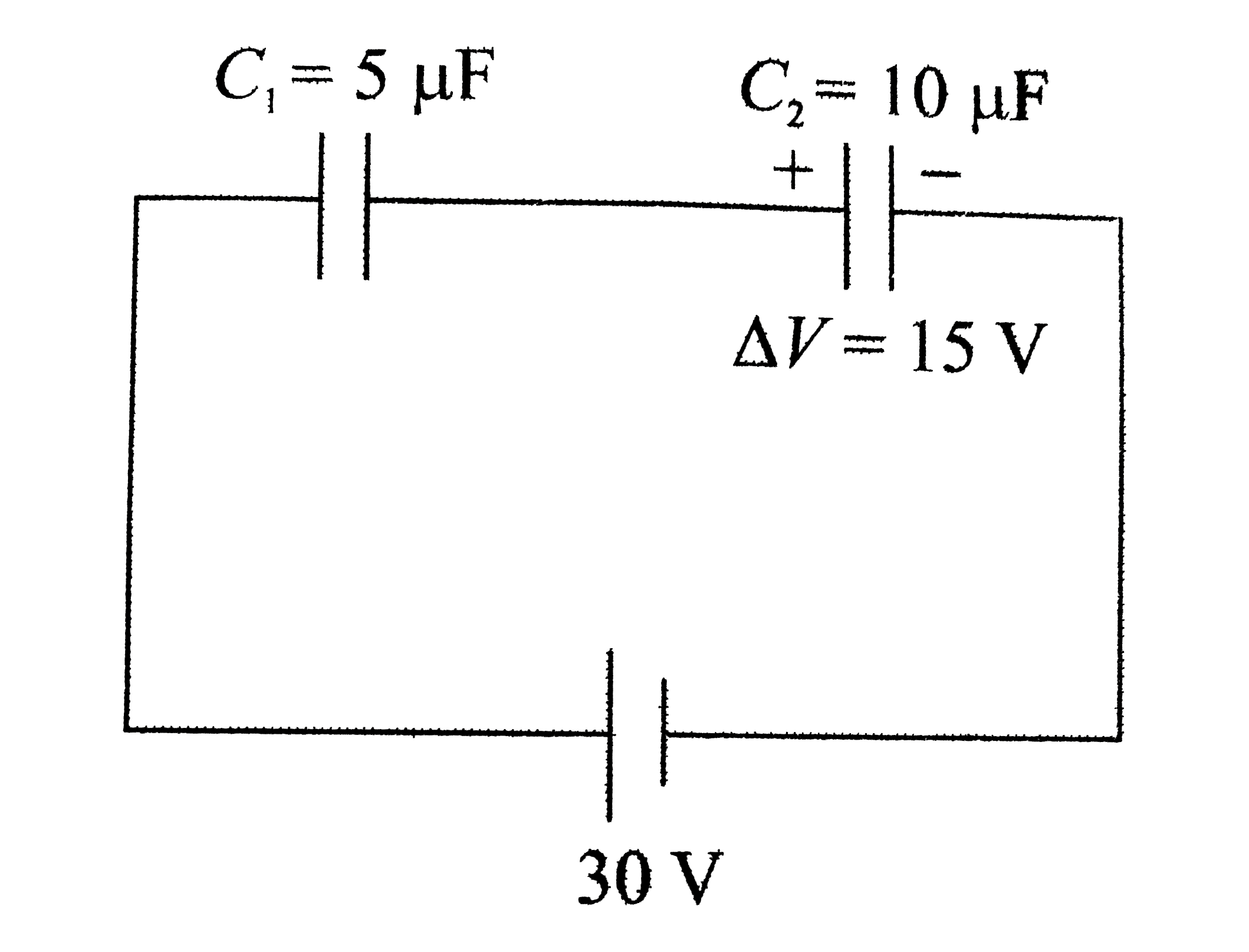
View SolutionA `10 muF` capacitor is charged to `15 V`. It is next connected in seties with an uncharged `5 muf` capacitor. The series cambination is finally connected across a `30 V` battery, as shown in. Find the new potential differnce across the `5 muF` and `10 muF` capacitors.
View SolutionConsider the situation shown in figure (31-E23 ) . The switch S is open for a long time and then closed . (a) Find the charge flown through the battery when the switch S is closed (b)Find the done by the battery .

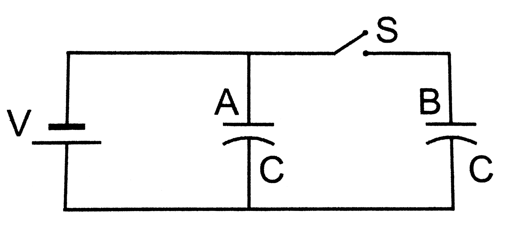
View SolutionFigure shows two identical parallel plate capacitors connected to a switch `S.` Initially ,the switch is closed so that the capacitors are completely charged .The switch is now opened and the free space between the plates of the capacitors is filled with a dielectric of dielectric constant 3. Find the ratio of the initial total energy stored in the capacitors to the final total energy stored.
View SolutionFour parallel large plates separated by equal distance d are arranged as shown in. The area of the plates is `S` Find the potential differnce between plats `B and C` if plate `B` is given a charge Q.
 .
.
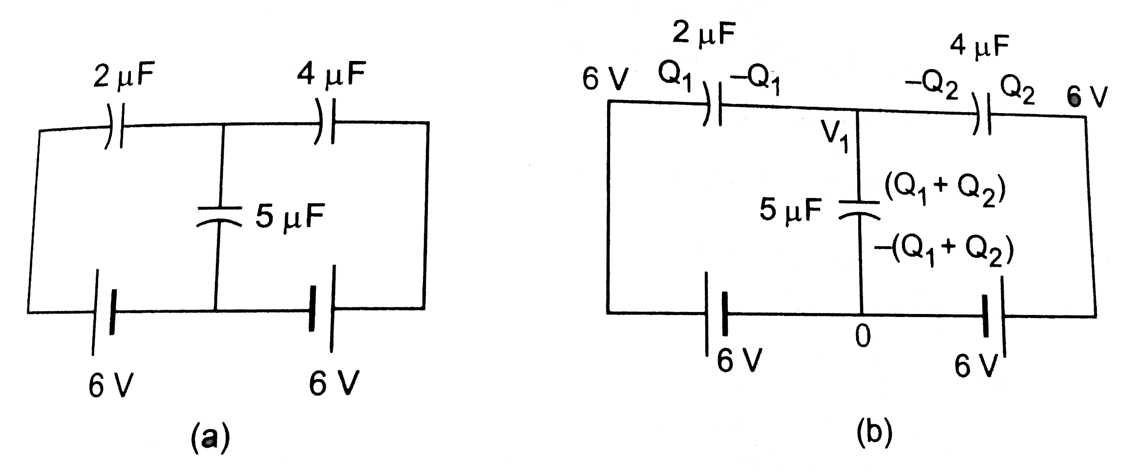
View SolutionFind the charges on the three capacitors shown in figure
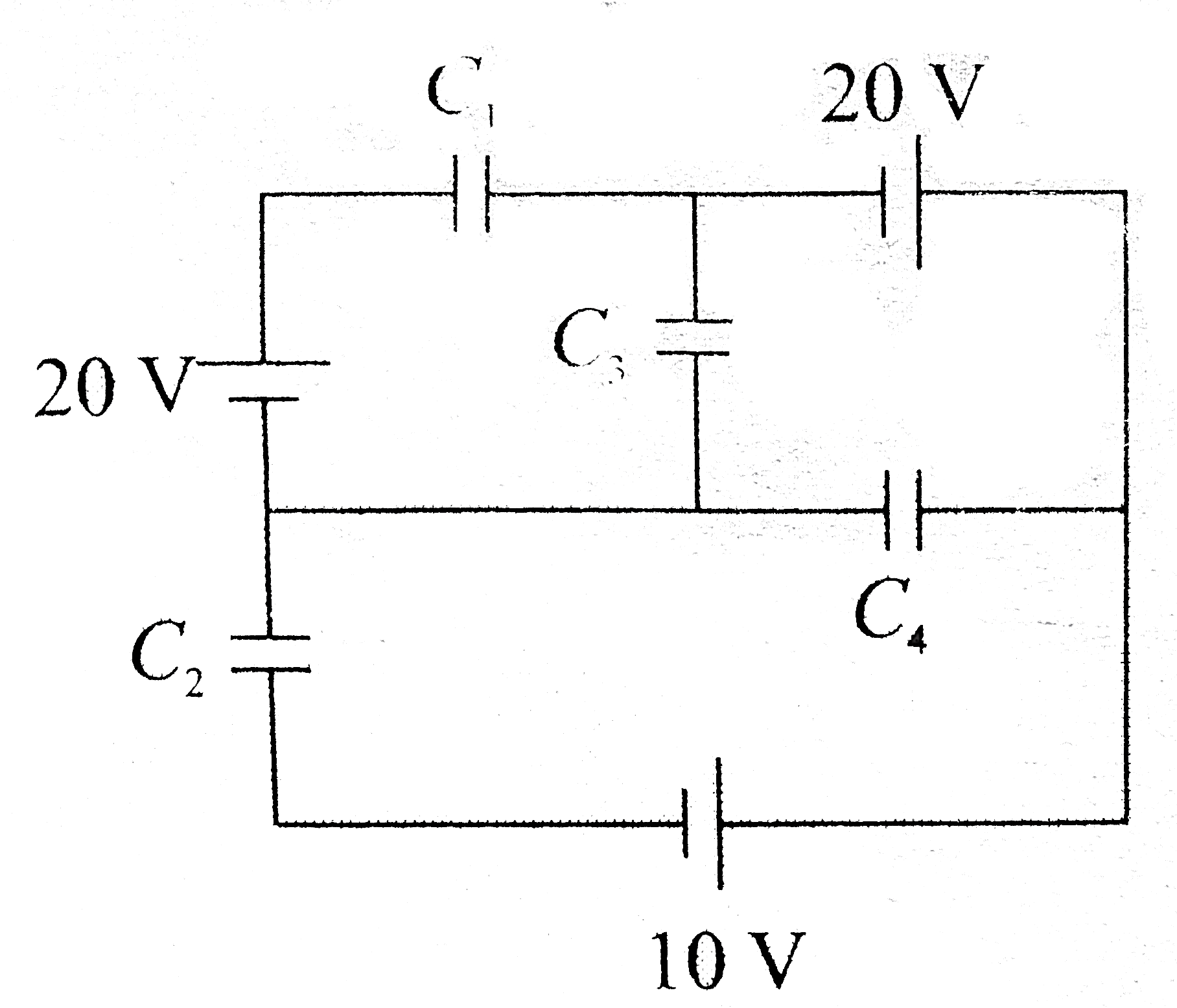
View SolutionFour capacitors `C_(1)=8 muF`,
`C_(2)=2 muf, C_(3)=6 muF`, and `C_(4)=6, muF` are arranged as shown in. Find the charge on all the capacitors in the circuit.
 .
.
View SolutionThree capacitors of capacitances `1 muF, 2 muF`, and `2 muF`, are cahrged up to the potential difference `30 V, 10 V`, and `15 V`, respectivly. If terminal `A` is connected with `D C` is connected with E and F is connected eith B, the find the charge flow in the ciruit and the final charge on the capacitors.
 .
.
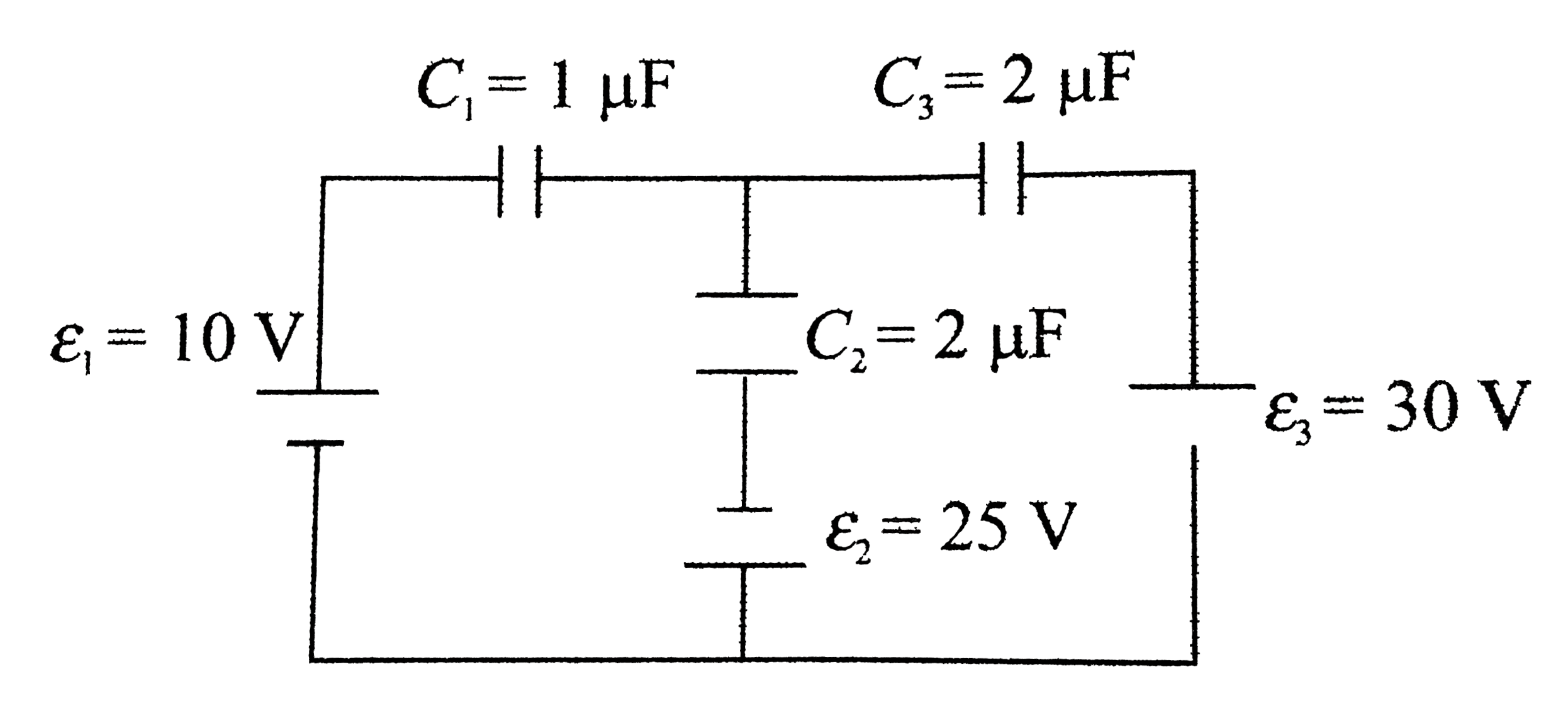
View SolutionThree initially uncharged capacitors are arranged with batteries as shown in. Find the charge on each capacitor.
 .
.
View SolutionA capacitor of capacitance `C` which is initially charged up to a potential differnce `epsilon` is connected with a battery of emf `epsilon` such that the positive terminal of the battery is connected with the positive plate of the capacitor. Find the heat loss in the circuit the process of charging.
View SolutionA `5.0muF` capacitor is charged to `12V`. The positive plate of this capacitor is now connected to the negative terminal of a `12V`battery and vice versa . Calculate the heat developed in the connecting wires.
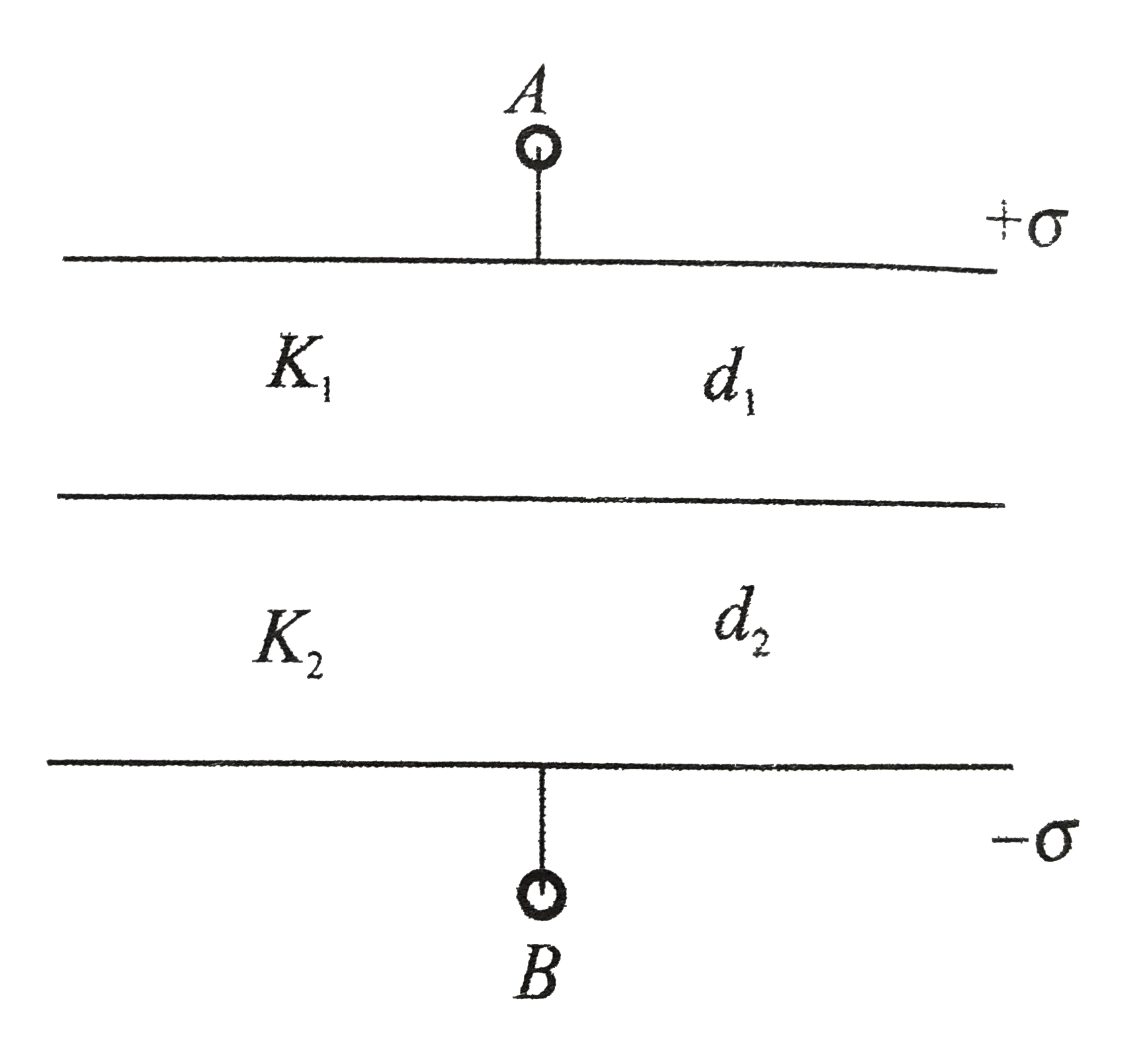
View SolutionFind the capacitance between A and B if two dielectric alabs (each of area `A`) of dielectric constants `K_(1)` and `K_(2)` and thicknesses `d_(1)` and `d_(2)` are inserted between the plates of a parallel plate capacitor of plate area `A`.
 .
.
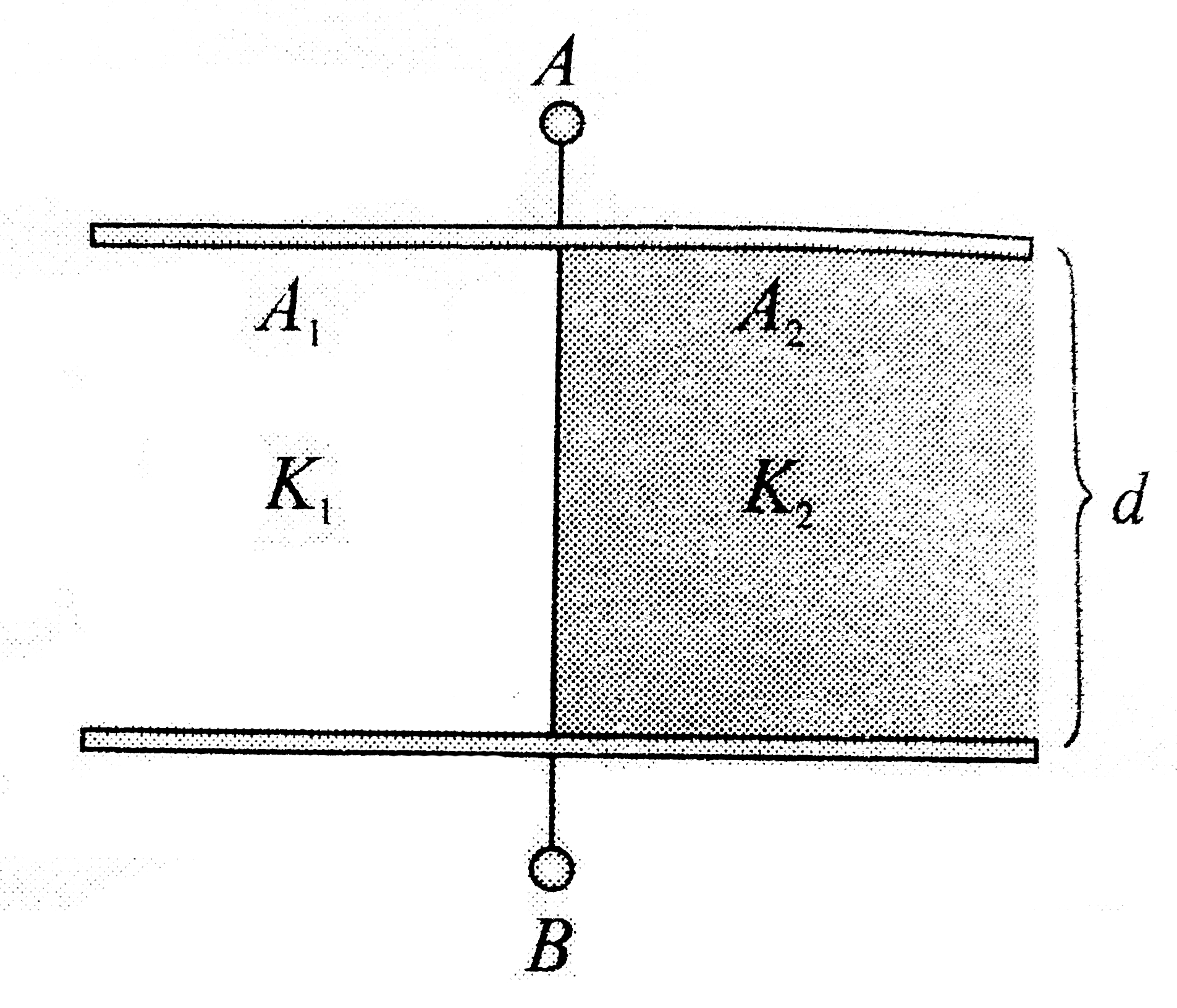
View SolutionFind the capacitance between A and B if two dielectric slabs (each of thickness d) of dielectric constants `K_(1)` and `K_(2)` and areas `K_(1)` and `K_(2)` and inserted between the plates of a parallel plate capacitor of plate area `A`.
 .
.
View SolutionFind the capacitance between A and B if three dielectric slabs of dielectric constants `K_(1) area `A _(2)` and thickness `d_(2)`) are inserted between the plates of a parallel late capacitor of plate area A. (Given that the distance between the two plates is `d_(1)=d_(2)+d_(2)`.)
 .
.
View SolutionThree dielectrics of relative permittivities `epsilon_(r_(1))=1,epsilon_(r_(2))=2`, and `epsilon_(r_(3))=3`
are introduced in a parallel plate capacitor of plate A and B.
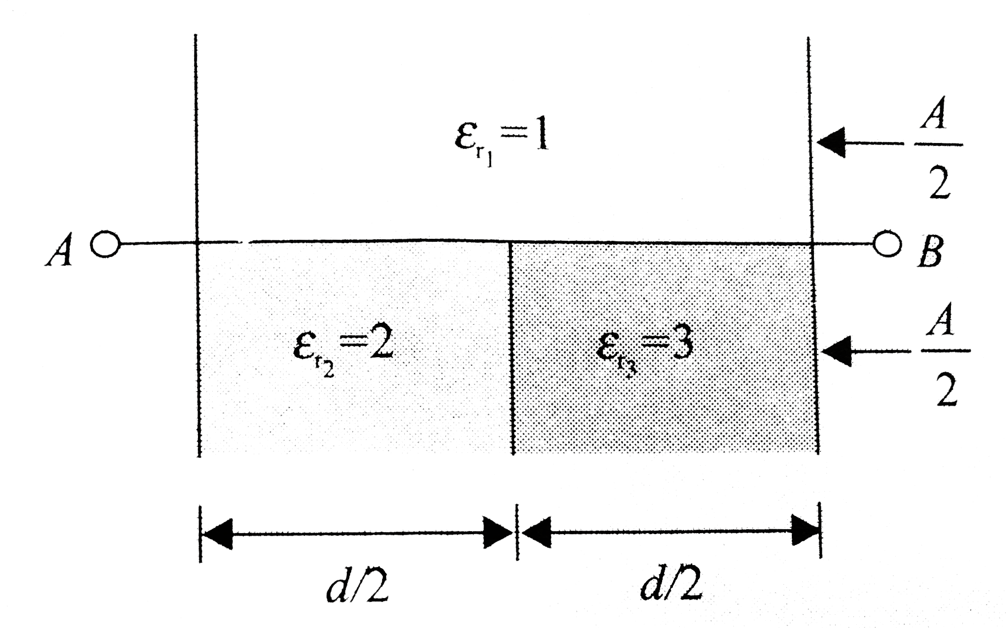 .
.
View Solution`T` Two capacitors of capacitances `1 muF` and `2 muF` are charged to potential differnces `20 V` and `15 V` as shown in. If terminals B and C connected together and terminals A and D are connected with the positive and negative ends of the battery, respectively, then find the final charges on both the capacitors.
 .
.
View Solution
Exercise 4.2 questions and complete solutions for chapter CAPACITOR AND CAPACITANCE of CENGAGE PHYSICS (HINGLISH) of Class 12