Complete Solutions to Comprhension of chapter CAPACITOR AND CAPACITANCE of Class 12 book with complete answers and questions
| Class 12 | PHYSICS |
| Chapter | CAPACITOR AND CAPACITANCE |
| CENGAGE PHYSICS | Comprhension |
| Number Of Questions | 35 |
| Academic Year | 2023-24 |
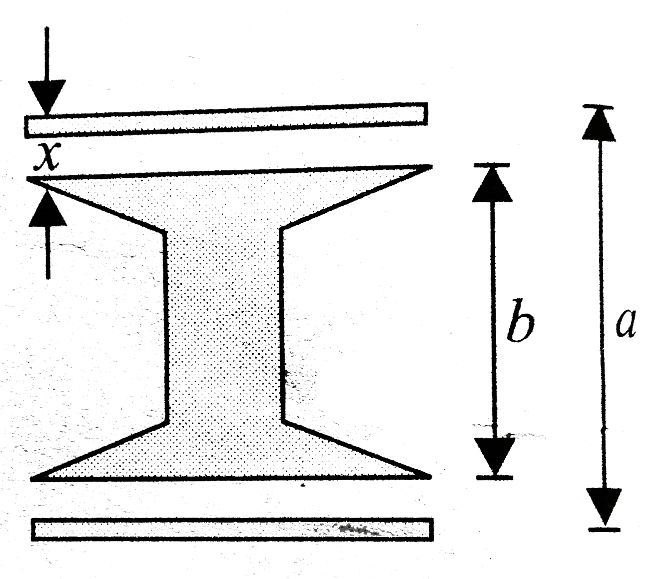
Shows two capacitors in series, the rigid central conducting section of length `b` being movable vertically.
 .
.
The equivalent capacitance of the given structure is .
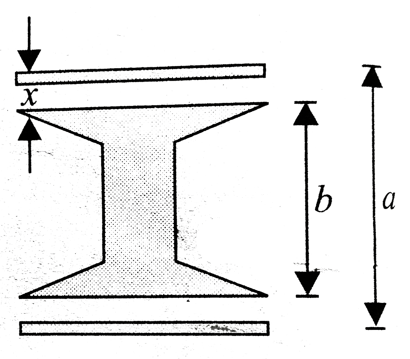
View Solutionshows two capacitors in series, the rigid central conducting section of length `b` being movable vertically.
 .
.
If the potentials of the upper and lower plates are `V_(1)` and `V_(2)` respectively, then potebtial of rigid segid secton is.
View SolutionA `1muF` capacitor and a `2µF` capacitor are connected in series across a `1200 V` supply line.
a. Find the charge on each capacitor and the voltage across them.
b. The charged capacitors are disconnected from the line and from each other and reconnected with terminals of like sign together. Find the final charge on each and the voltage across them.
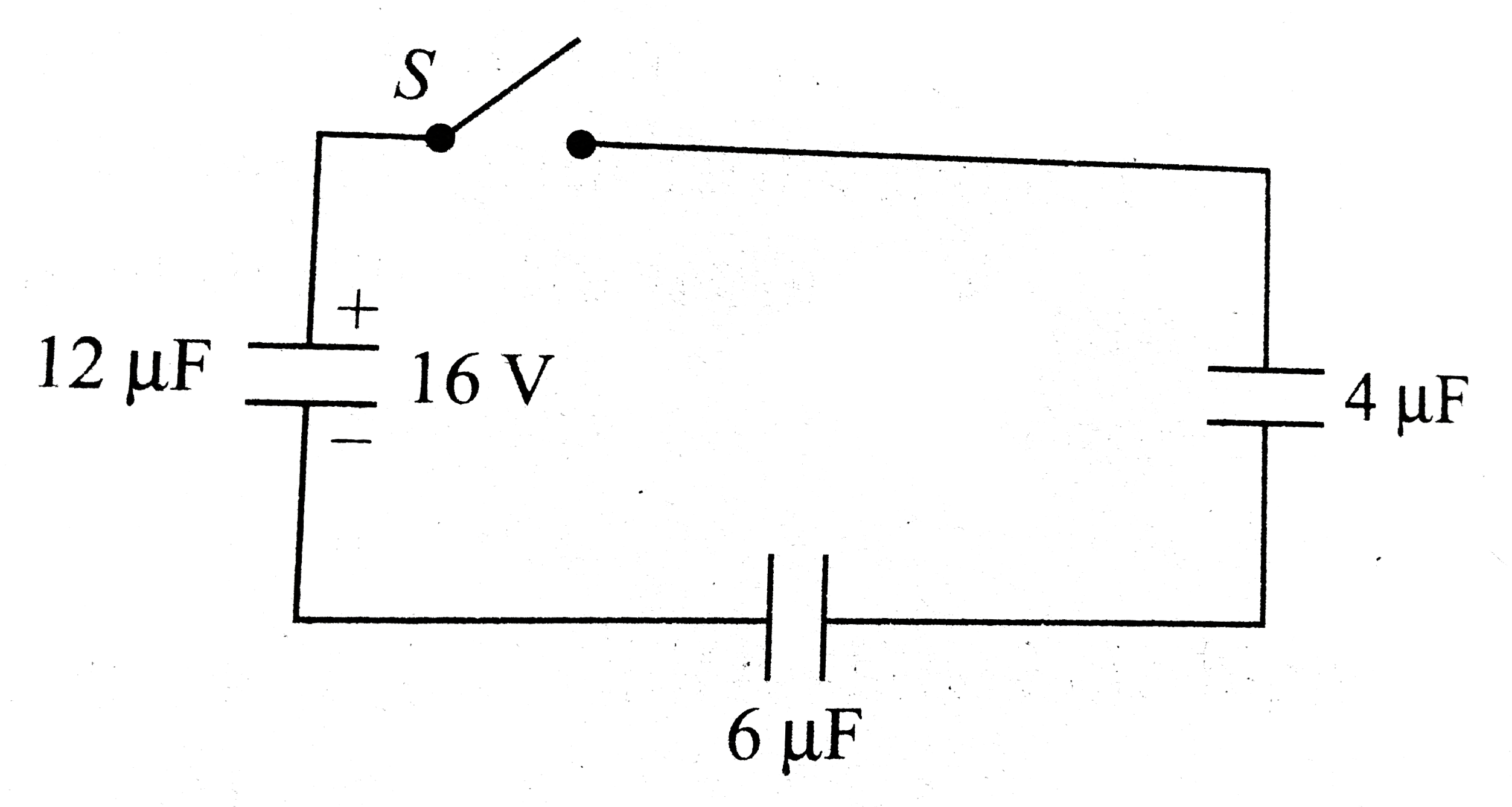
View SolutionIn the arrangement shown in in the switch `S` is , find
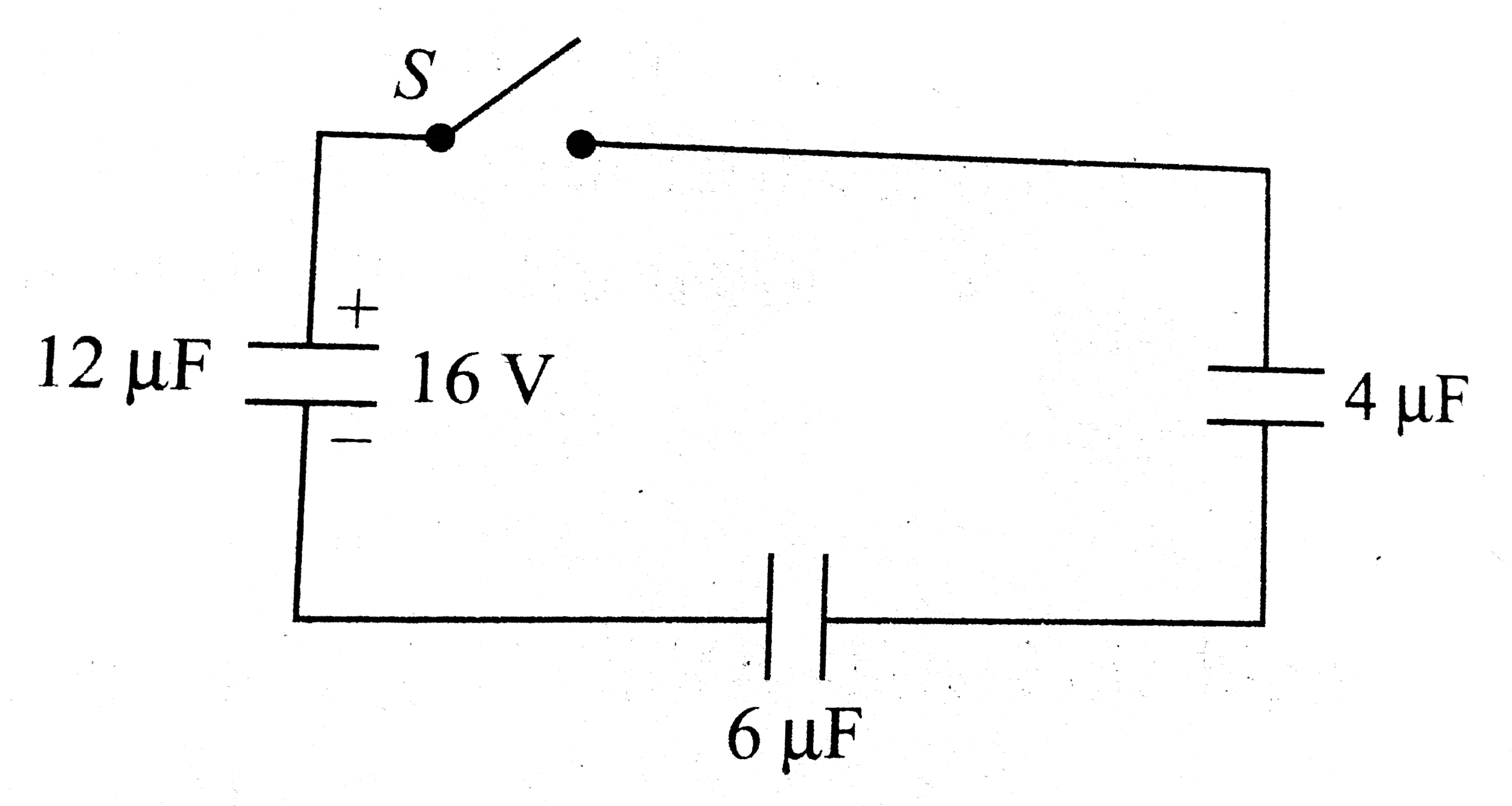
the final charge on the `6 mu F` capacitor
View SolutionIn the arrangement shown in , the switch `S` is find
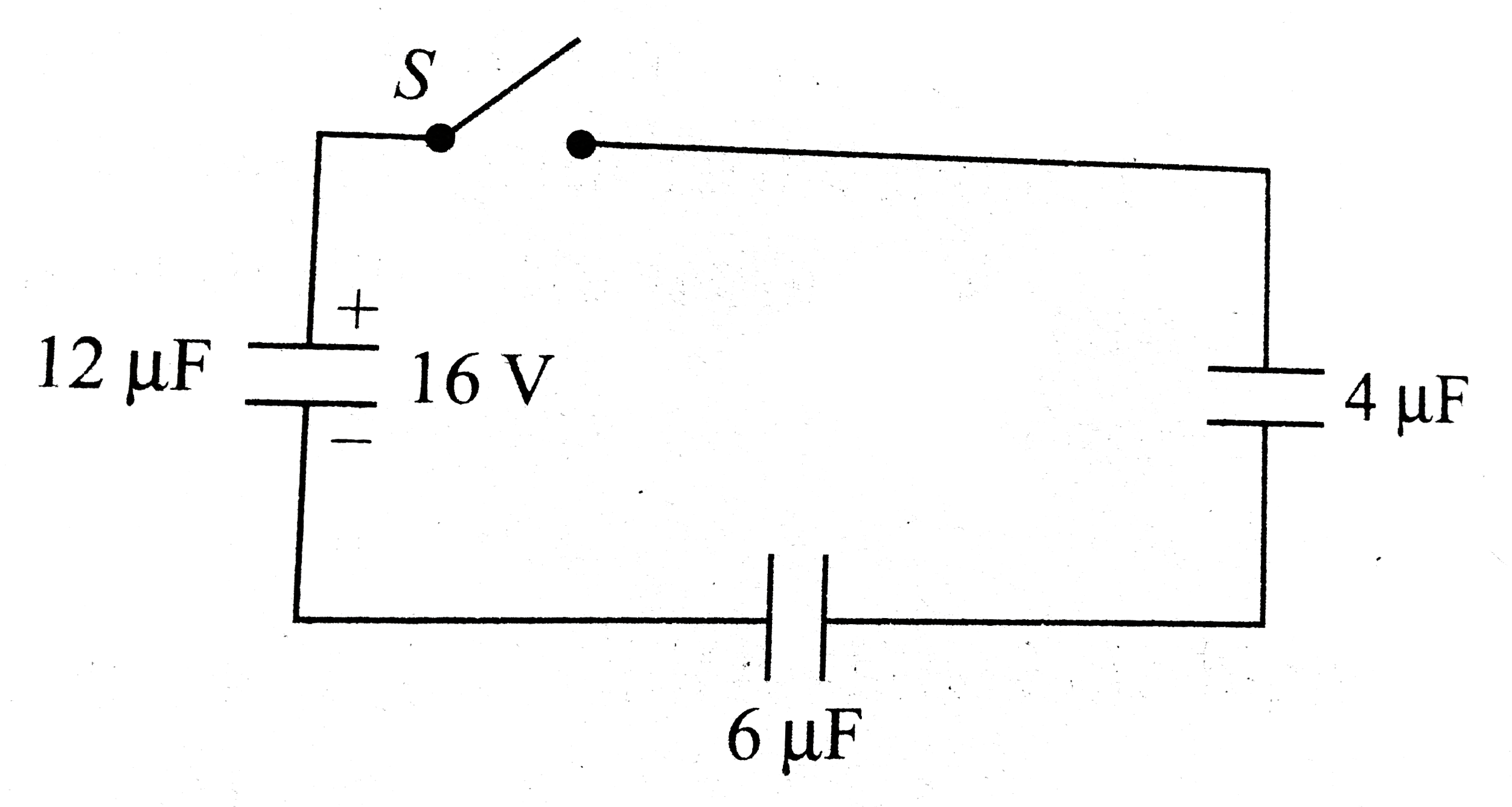 the final potential difference across the `4 mu F` capacitor
View SolutionIn the arrangement shown in, When the switch S is closed, find
 .
.
the final potential difference across the `12 muF` capacitor.
View SolutionEach plate of a parallel plate air capacitor has area `S=5xx10^(-3) m^(2)` and the distance between the plates is `d=8.80 mm`. Plate A has positive charge `q_(1)=+10^(-10) C`, and plate B has charge `q_(2)=+2xx10^(-10) C`. A battery of emf `E=10 V` has its positive terminal connected to plate A and the negative terminal to plate B. (Given `epsilon_(0)=8.8xx^(12) Nm^(2) C^(-2))`.
Charge supplied by time the battery is .
View SolutionEach plate of a parallel plate air capacitor has area `S=5xx10^(-3) m^(2)` and the distance between the plates is `d=8.80 mm`. Plate `A` has positive charge `q_(1)= +10^(-10) C`, and plate `B` has charge `q_(2)=+2xx10^(-10) C`. A battery of emf `E=10 V` has its positive terminal connected to plate `A` and the negative terminal to plate `B`. (Given `epsilon_(0)=8.8xx10^(12) Nm^(2) C^(-2))`.
Energy supplied by the battery is.
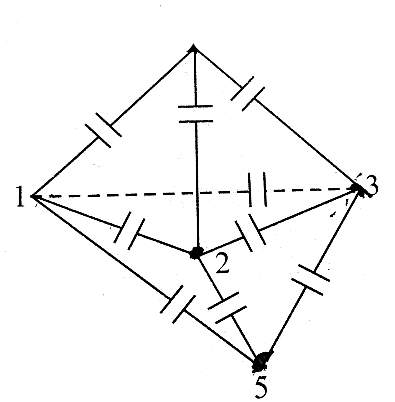
View SolutionEach capacitor has cpacitance `C`.
 .
.
The equivalent capacitance between `4` and `5` is .
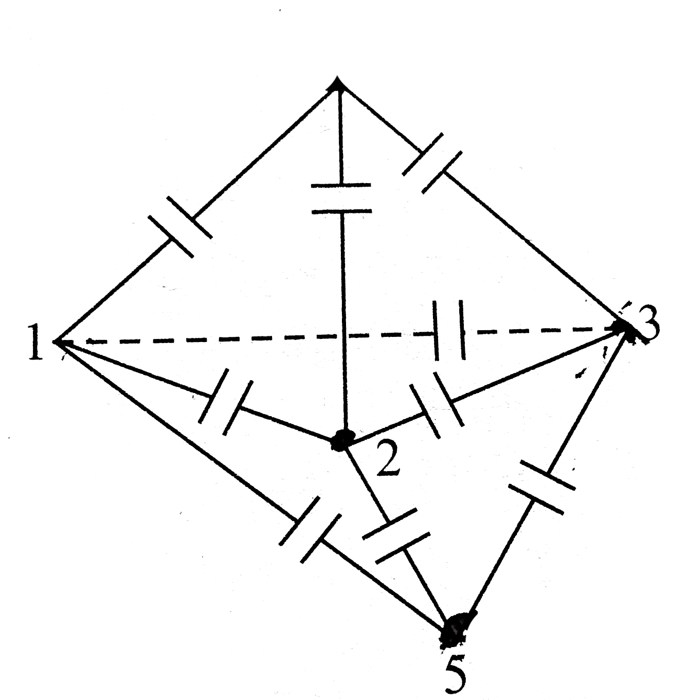
View SolutionEach capacitor has capacitance C.
 .
.
The capacitance between `1` and `3` is.
View SolutionConsider
` .
.
The charge appearing is `C_(2)` is.
View SolutionConsider
 .
.
The potential difference `V_(A)-V_(B)` is.
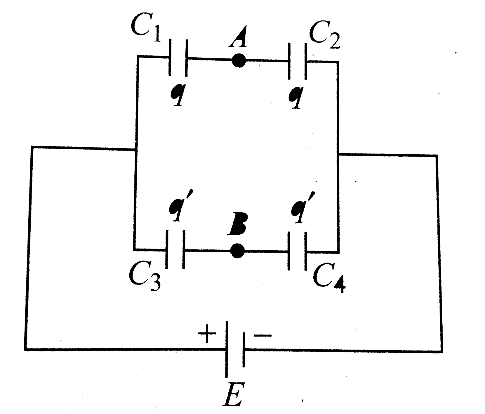
View SolutionConsider
 .
.
The condition for which the potential difference between A and B is zero is.
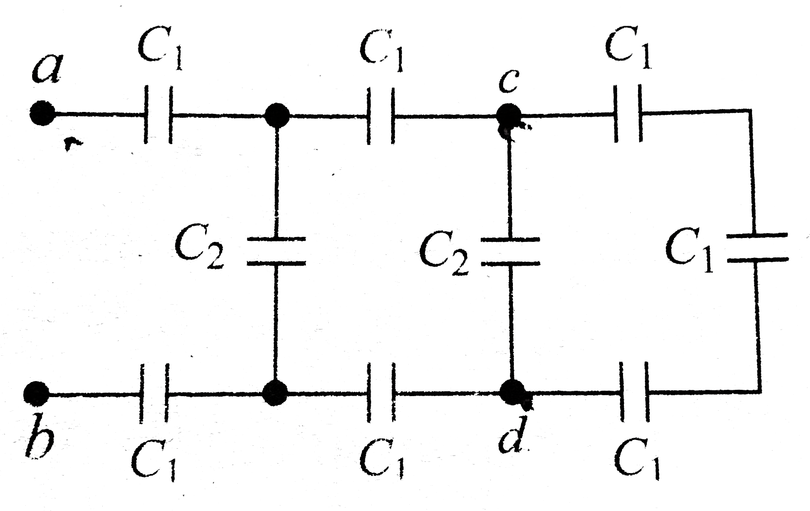
View SolutionIn each capacitance `C_(1)` is `6.0 muF`, and each capacitance `C_(2)` is `4.0 muF`.
 .
.
The equivalent capacitance of the netwok between ponts a and b is.
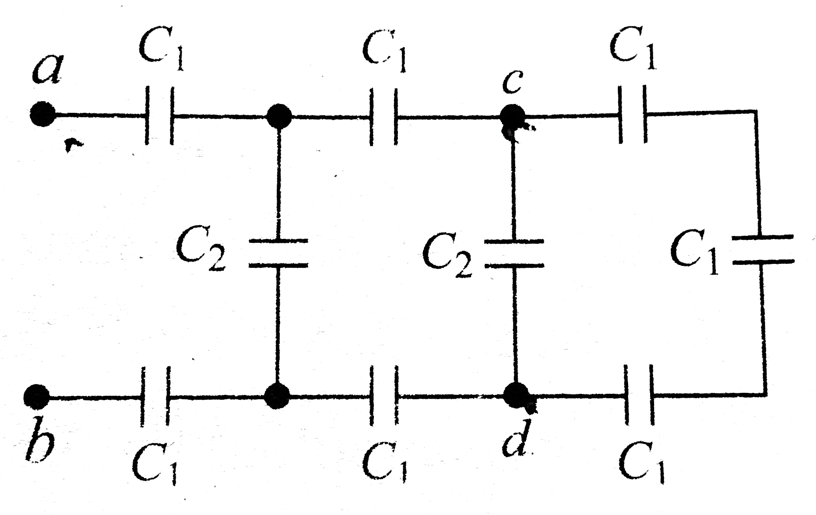
View SolutionIn each capacitance `C_(1)` is `6.0 muF`, and each capacitance `C_(2)` is `4.0 muF`.
 .
.
The charge on `C_(1)` nearest to `a` when `V_(ab)=420 V` is.
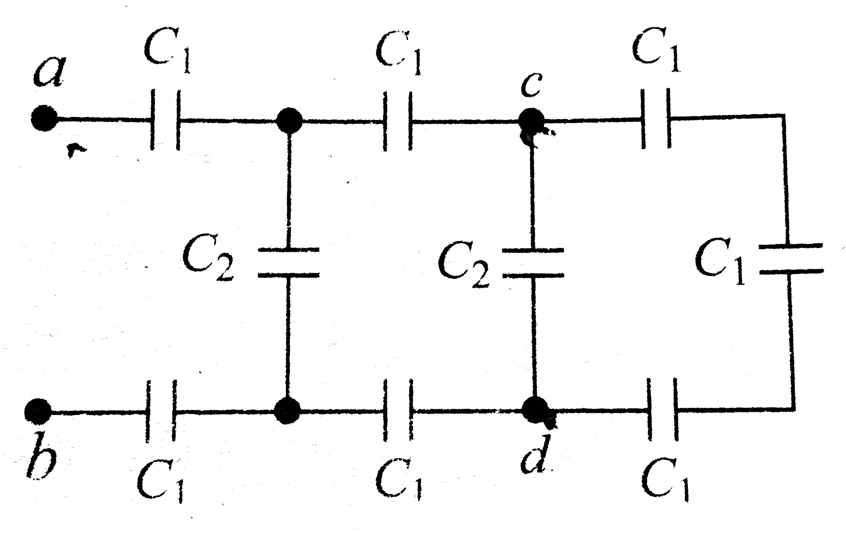
View SolutionIn each capacitance `C_(1) is 6.0 muF`, and each capacitance `C_(2)` is `4.0 muF`.
 .
.
With `420 V` across a and b the value of `V_(c)-V_(d)` is.
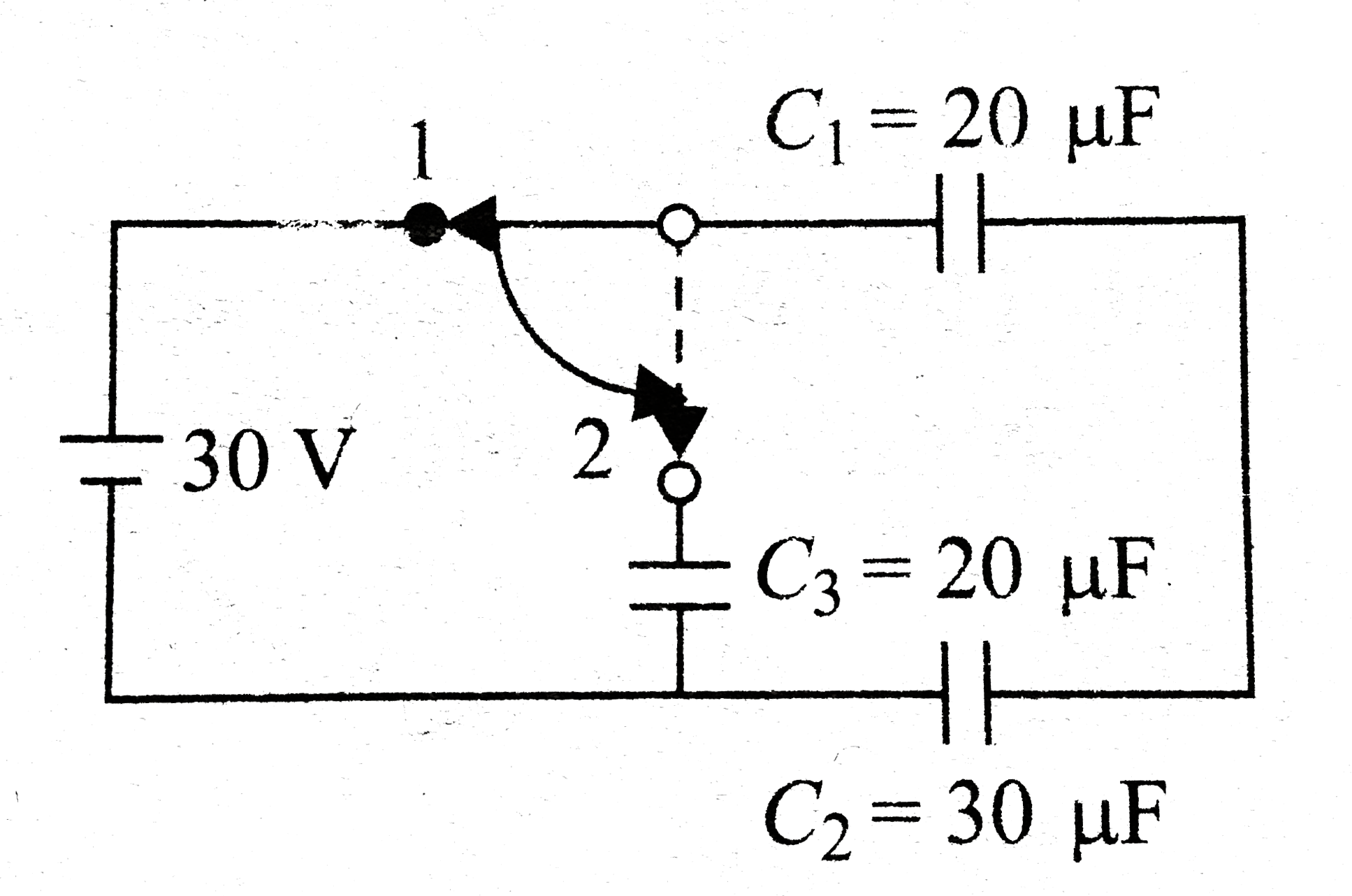
View SolutionCondsider
 .
.
In the circuit shown is the switch can be shifted to positions `1` and `2` The charge on capacitor `C_(1)` when the switch is at position `1` is.
View SolutionCondsider
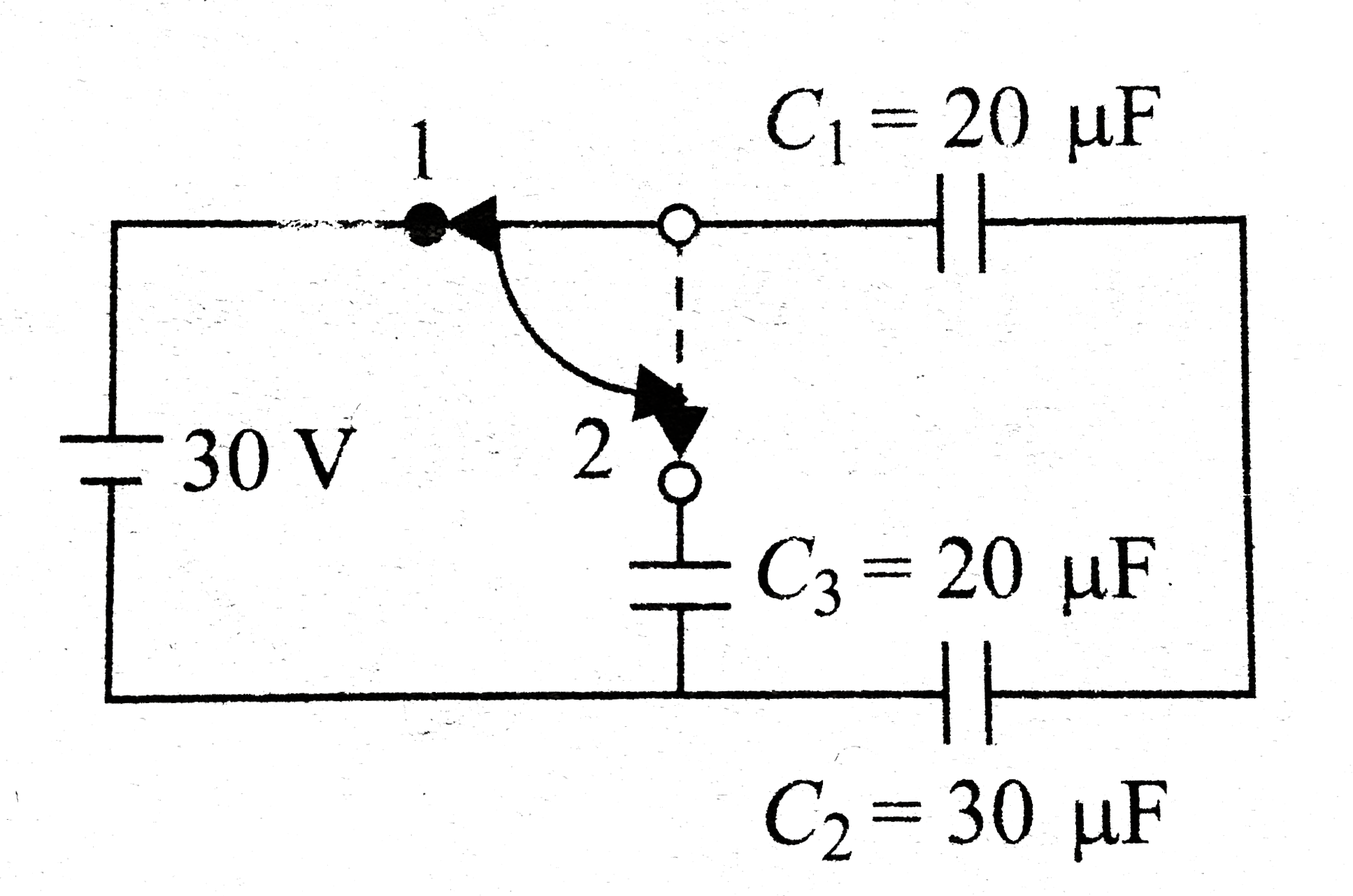 .
.
Now the switch is shifted to position `2`. The charge appearing on capacitor `C_(3)` is`
View SolutionCondsider
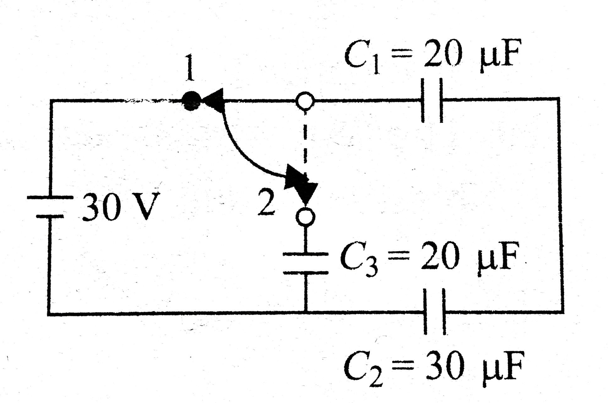 .
.
The charge on capacitor `C_(1)` is.
View SolutionFor the system shown in capacitance is `C` The left plate is given a charge `Q_(1)` and the is closed.
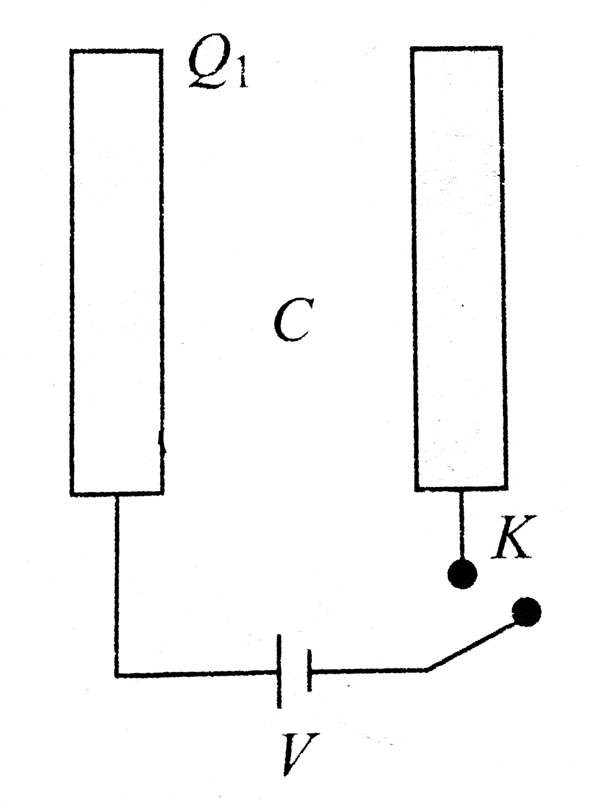 .
.
Find the amount of charge that will flow through the battery before the steady state is achieved.
View SolutionFor the system shown in capacitance is `C` The left plate is given a charge `Q_(1)` and the is closed.
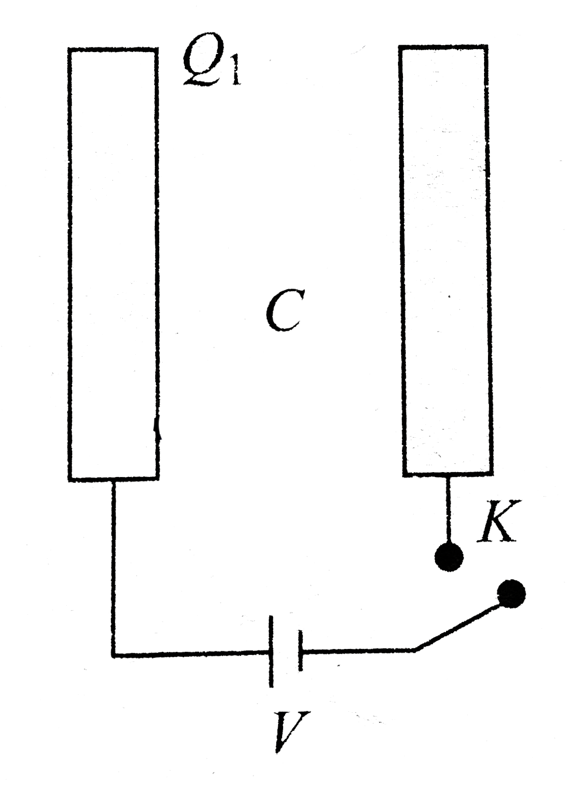 .
.
Find the charge appearing on the inner face of the left plate.
View SolutionConsider the circuit shown is after switch S is closed.
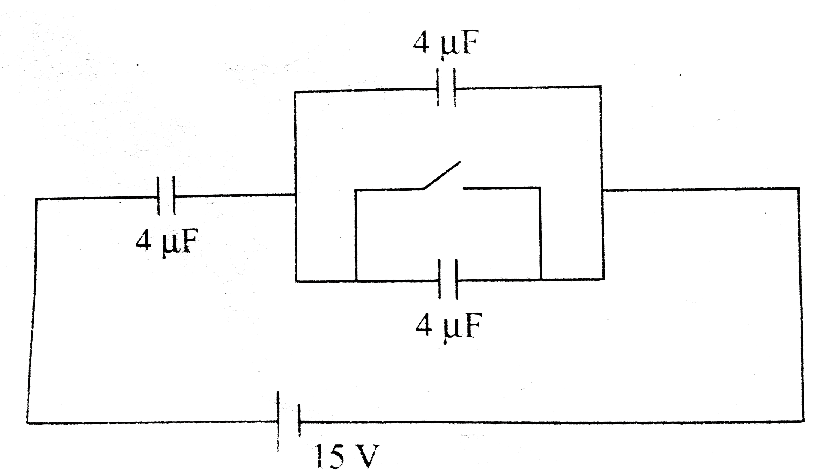
What amount of charge will flow through the battery ?
View SolutionConsider the circuit shown is after switch S is closed.
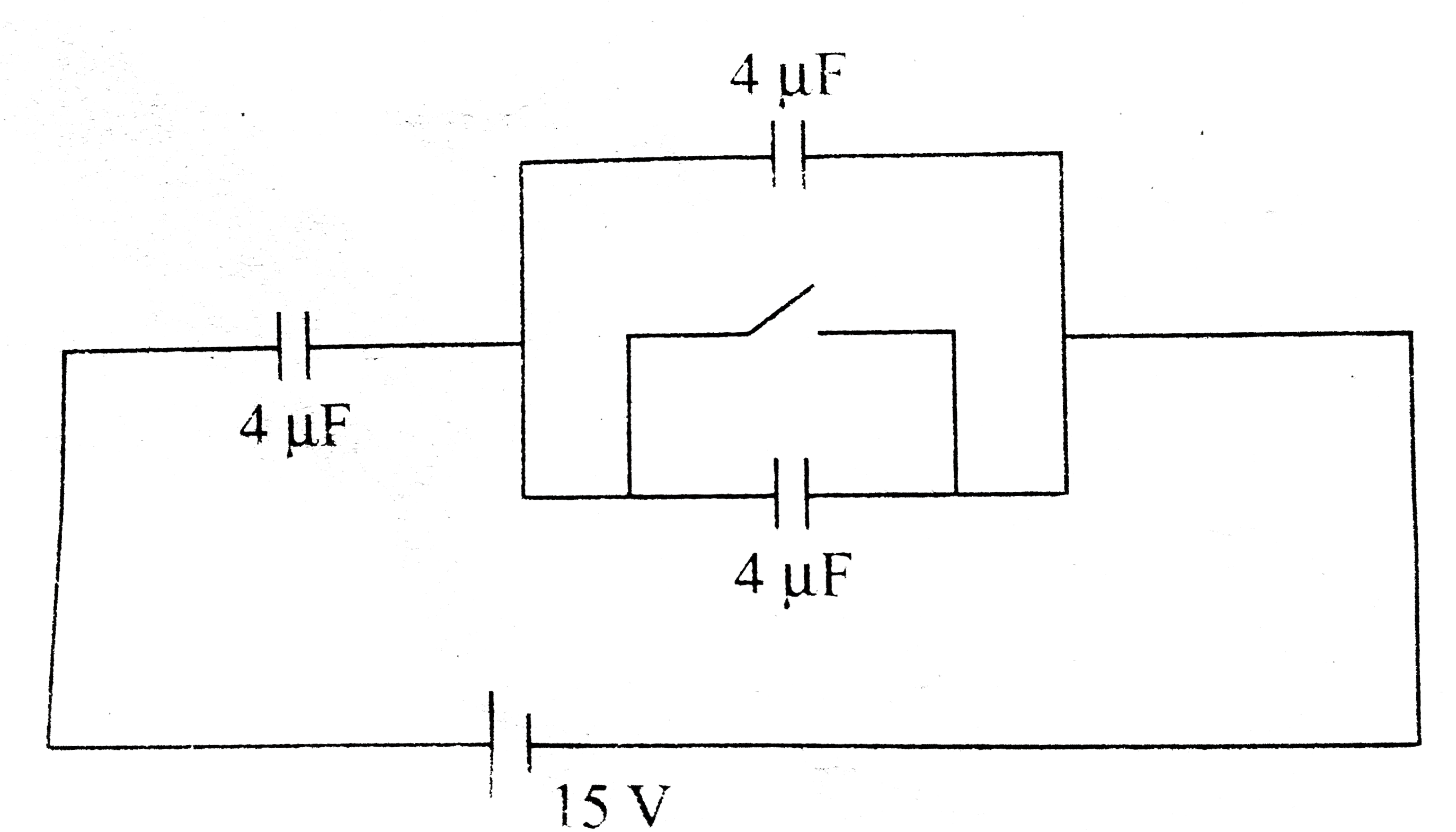
What amount of charge will flow through the switch?
View SolutionTwo capacitors of capacity `6 muF` and 3 muF` are charge `100 V` and `50 V` separately and connected as shown in Now all the three switches `S_(1),S_(2)`, and `S_(3)` are closed.
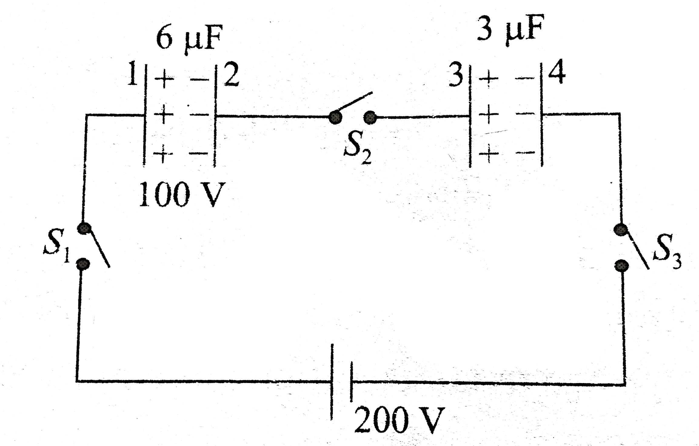
Which plates form an isolated system?
View SolutionTwo capacitors of capacity `6 muF` and `3 muF` are charge `100 V` and `50 V` separately and connected as shown in (Fig.4.201.) Now all the three switches `S_(1),S_(2)`, and `S_(3)` are closed.
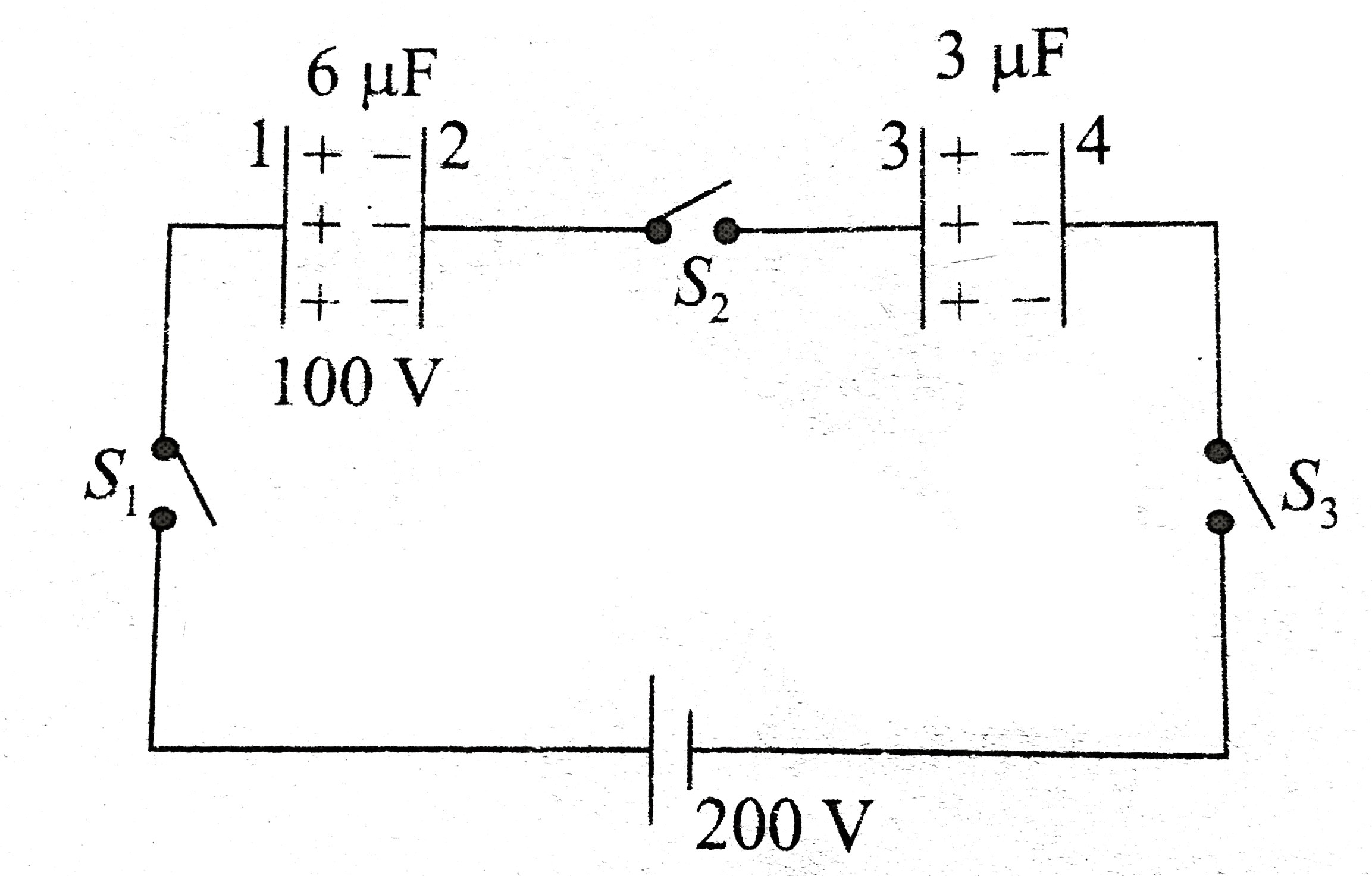
Charge on the `6 muF` capacitor in steady state will be.
View SolutionTwo capacitors of capacity `6 muF` and `3 muF` are charge `100 V` and `50 V` separately and connected as shown in Now all the three switches `S_(1),S_(2)`, and `S_(3)` are closed.
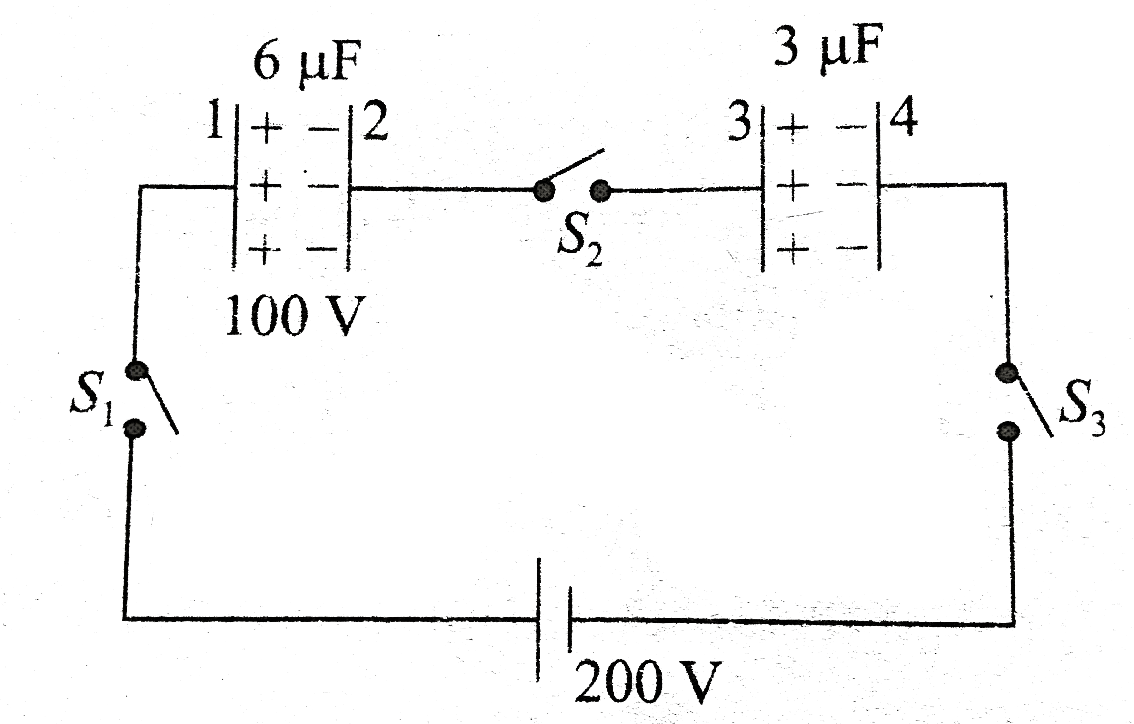
Charge on the `3 muF` capacitor in steady state willl be.
View SolutionTwo capacitors of capacity `6 muF` and `3 muF` are charge `100 V` and `50 V` separately and connected as shown in Now all the three switches `S_(1),S_(2)`, and `S_(3)` are closed.

Which plates form an isolated system?
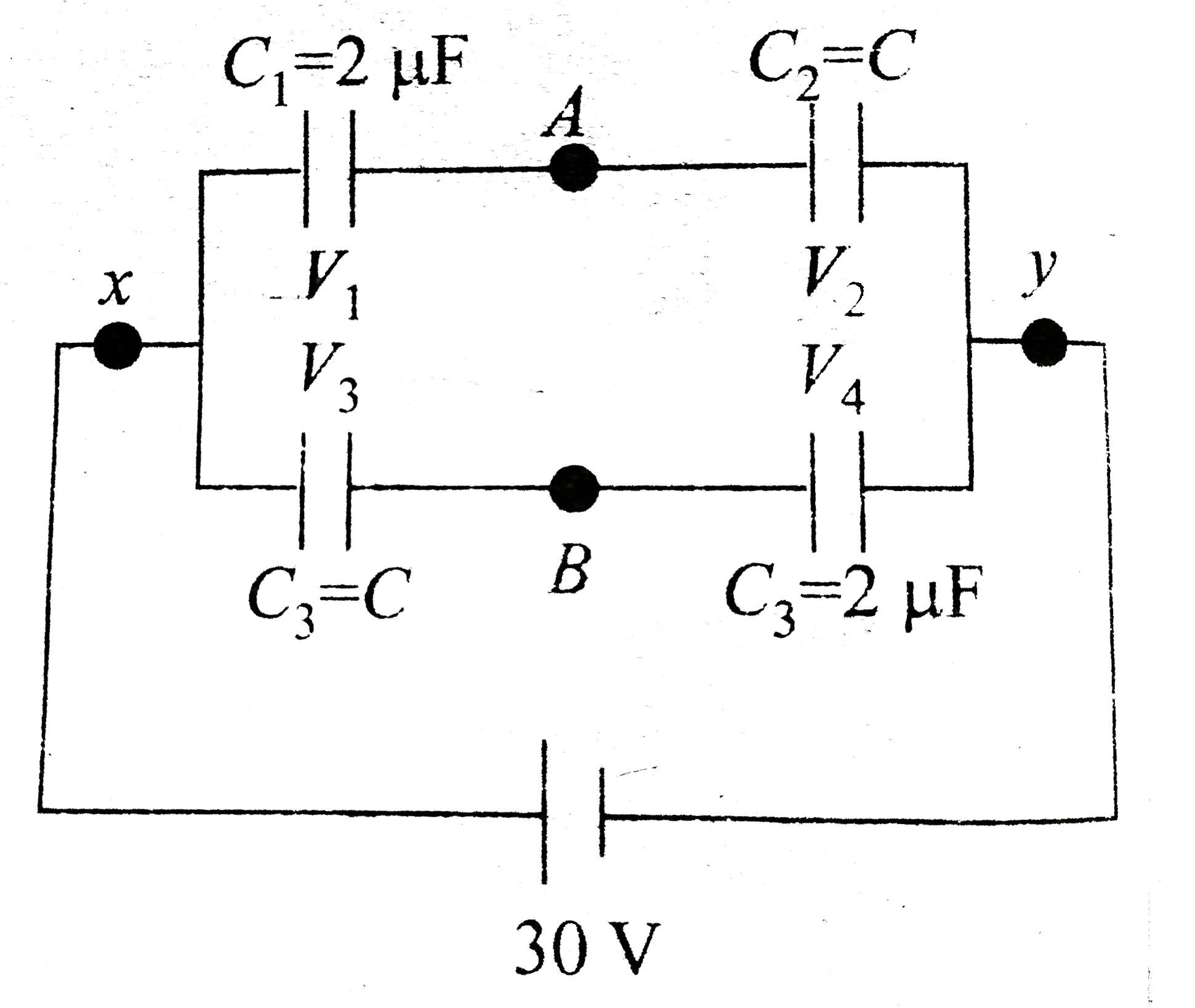
View SolutionThe given circuit shows an arrangement of four capacitors. A potential difference `30 V` is applied across the combination. It is observed that potentials at connected between `A an dB` differ by `5 V`. Also if a conducting wire is connected between `A and B`, electrons will flow from `A` to `B`. Of course, we have bot actually connected any wire between `A and B`, we have described only an `if` situation. Answer the following question.
 .
.
Potential difference across `C_(4)` is.
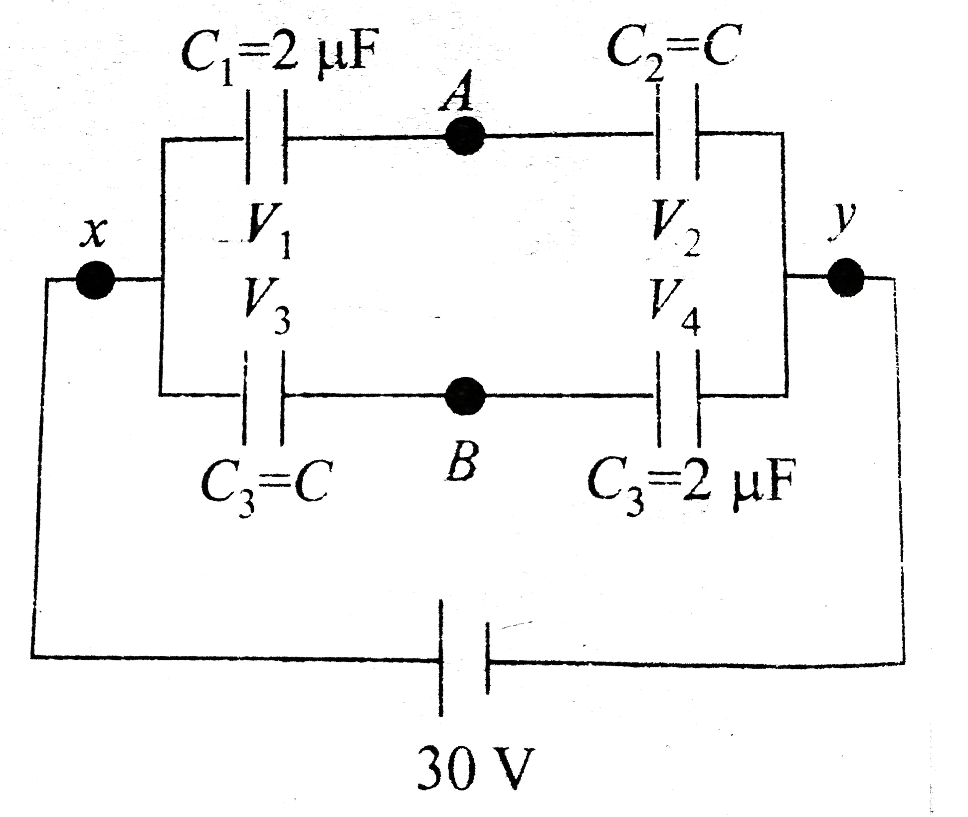
View SolutionThe given circuit shows an arrangement of four capacitors. A potential difference `30 V` is applied across the combination. It is observed that potentials at connected between A and B differ by `5 V`. Also if a conducting wire is connected between A and B, electrons will flow from `A` to `B`. Of course, we have bot actually connected any wire between `A and B`, we have described only an `if` situation. Answer the following question.
 .
.
Equivalent capacitor between `x` and `y` is.
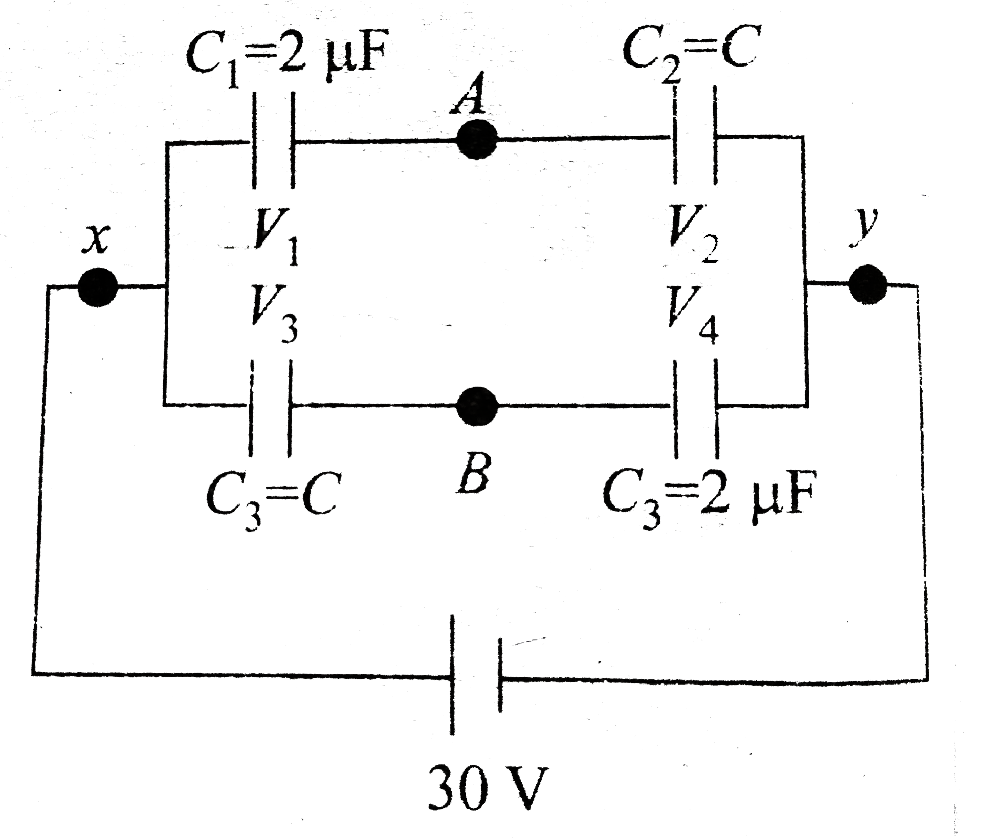
View SolutionThe given circuit shows an arrangement of four capacitors. A potential difference `30 V` is applied across the combination. It is observed that potentials at connected between `A` and `B` differ by `5 V`. Also if a conducting wire is connected between `A` and `B`, electrons will flow from `A to B`. Of course, we have bot actually connected any wire between `A` and `B`, we have described only an if situation. Answer the following question.
 .
.
Charge on capacitor `C_(1)` is.
View Solution
 .
.
Let us now connect two more capacitors in the circuit. One of them, `C_(5)`, is connected in the part of the circuit between `x` and `A`. It connected between either in series or in parallel with `C_(1)`. The other, `C_(6)`, is connected between `A and B`. It is observed `x and y` has the the same value `C_(5)` is.
Capacitance `C_(5)` is.
View Solution
 .
.
Let us now connect two more capacitors in the circuit. One of them, `C_(5)`, is connected in the part of the circuit between `X` and `A`. It connected between either in series or in parallel with `C_(1)`. The other, `C_(6)`, is connected between `A and B`. It is observed `X and Y` has the the same value `C_(5)` is.
Capacitance `C_(5)` will be.
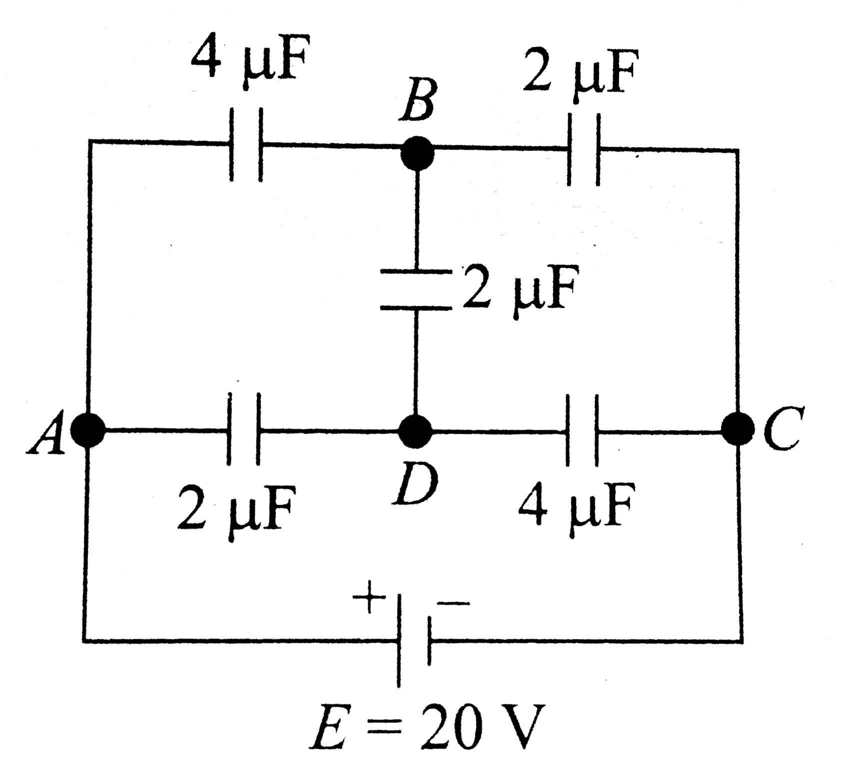
View SolutionShows a diagonal symmetric arrangement of capacitors and a battery. Identify the correct statements.
 .
.
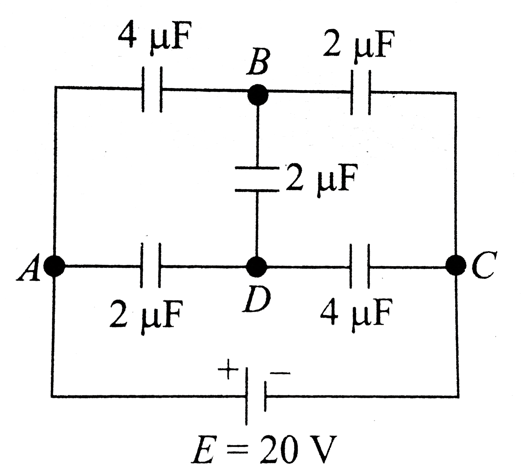
View SolutionShows a diagonal symmetric arrangement of capacitors and a battery.
 .
.
If the potential of `C` is zero, then identify the incorrect statement.
View Solution
Comprhension questions and complete solutions for chapter CAPACITOR AND CAPACITANCE of CENGAGE PHYSICS (HINGLISH) of Class 12