Complete Solutions to Level 2 Single Correct of chapter CURRENT ELECTRICITY of Class 12 book with complete answers and questions
| Class 12 | PHYSICS |
| Chapter | CURRENT ELECTRICITY |
| DC PANDEY | Level 2 Single Correct |
| Number Of Questions | 26 |
| Academic Year | 2023-24 |
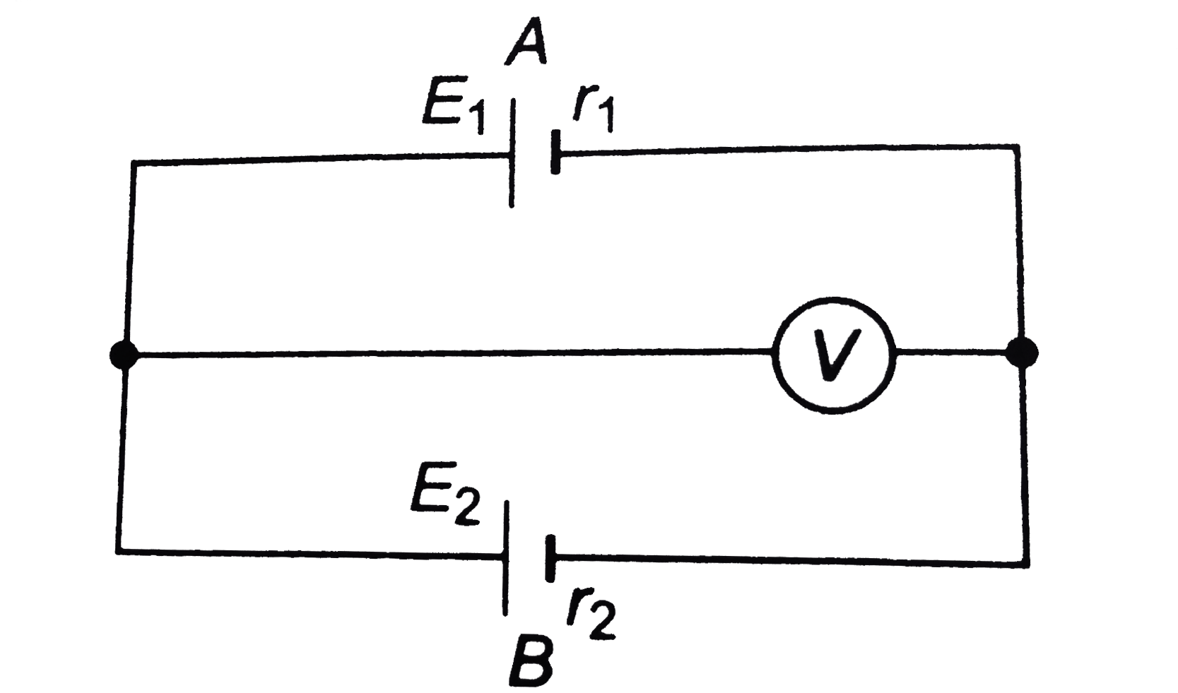
Two cells `A` and `B` of emf `1.3 V` and `1.5V `respectively are arranged as shown in figure. The voltmeter reads `1.45V`. The voltmeter is assumed to be ideal. Then
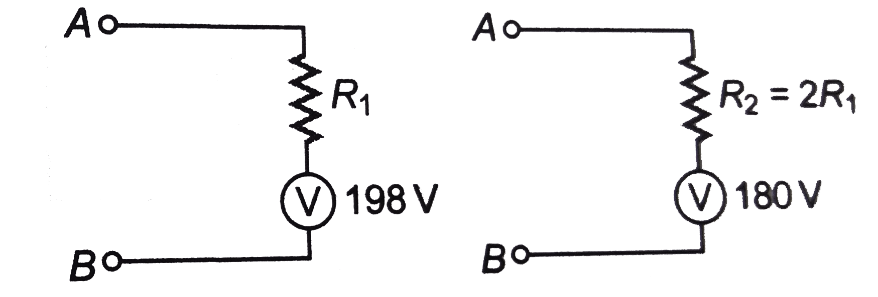
View SolutionA voltmeter connected in series with a resistance `R_1` to a circuit indicates a voltage `V_1=198V`. When a series resistor `R_2=2R_1` is used, the voltmeter indicates as voltage `V_2=180V`. If the resistance of the voltmeter is `R_V=900Omega`, then the applied voltage ( in volt ) across `A` and `B` is
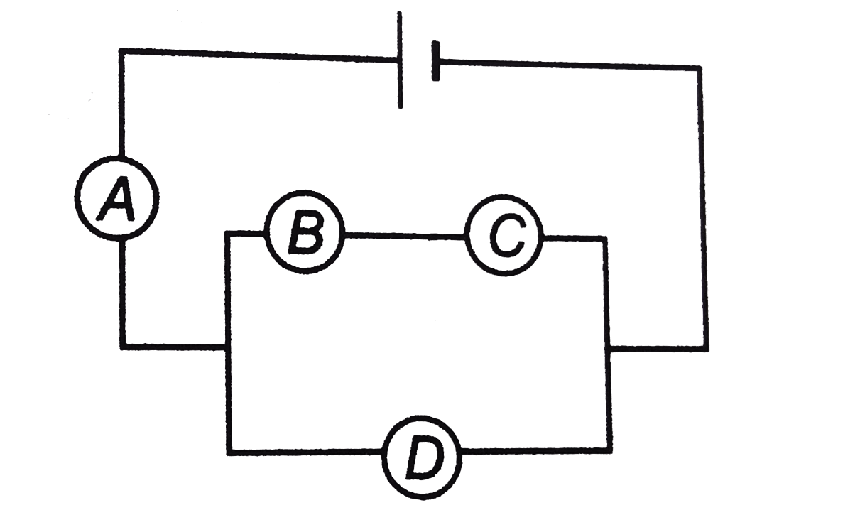
View SolutionAll bulbs in the circuit shown in figure are identical. Which bulb glows most brightly?
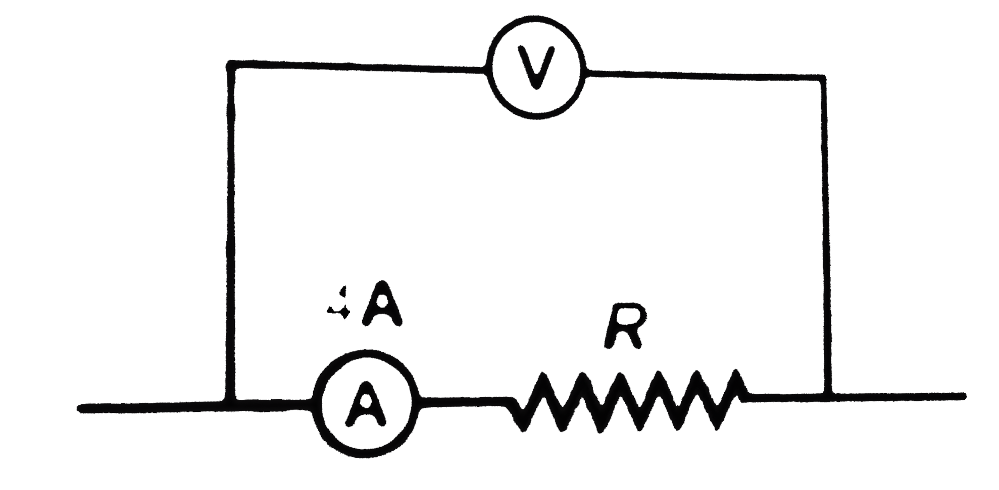
View SolutionA students connects an ammeter `A ` and a voltmeter `V` to measure a resistancer as shown in figure. If the voltmeter reads `20 V` and the ammeter reads `4A`, then `R` is
View SolutionThe given figure represents an arrangement of potentiometer for the calculation of internal resistance (`r`) of the unknown battery (`E`). The balance length is `70.0 cm` with the key opened and `60.0 cm` with the key closed. `R` is `132.40Omega`. The internal resistance (r) of the uknown cell will be
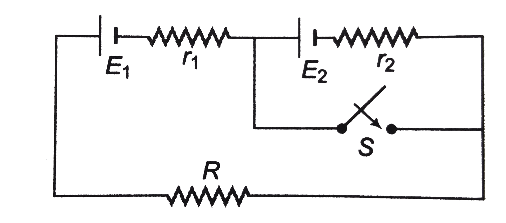
View SolutionSwitch `S` is closed at time `t=0`. Which one of the following statements is correct?
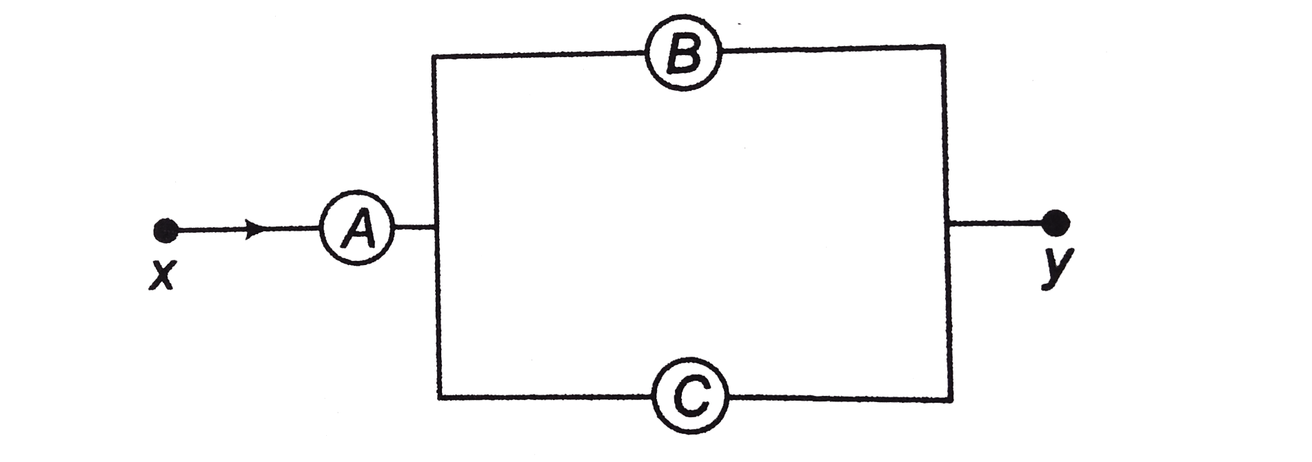
View Solution`A, B` and `C` are voltmeters of resistances `R, 1.5R` and `3R` respectively. When some potential difference is applied between `x` and `y` the voltmeter readings are `V_A, V`_B`and `V_C,` then
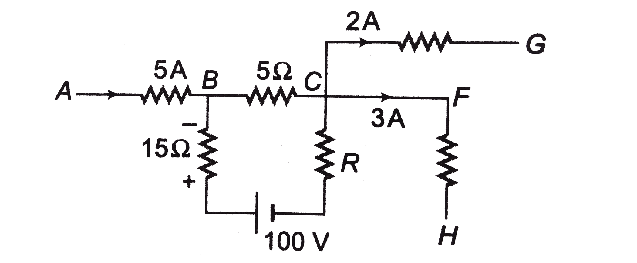
View SolutionIn the circuit shown the voltage drop across the `15Omega` resistor is `30 V` having the polarity as indicated. The ratio of potential difference across `5Omega` and resistance `R` is
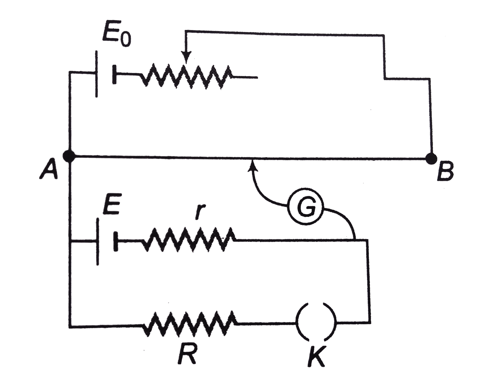
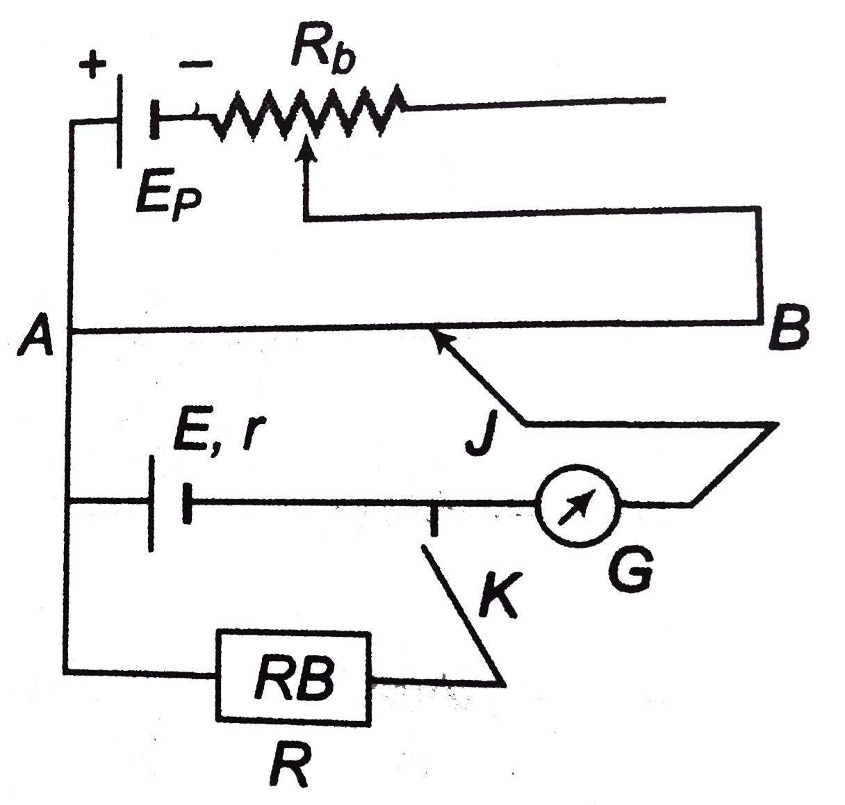
View SolutionIn an experiment on the measurement of internal resistance of as cell by using a potentionmeter, when the key `K` is kept open then balancing length is obtained at y metre. When the key `K` is closed and some resistance `R` is inserted in the resistance box, then the balancing length is found to be `x` metre. Then the internal resistance is
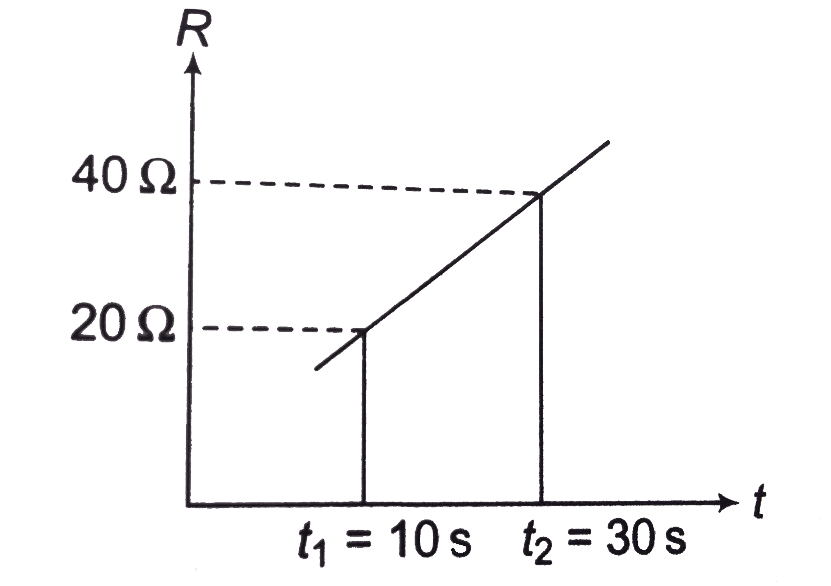
View SolutionA source of emf `E=10 V` and having negligible internal resistance is connected to a variable resistance. The resistance varies as shown in figure. The total charge that has passed through the resistor `R` during the time interval from `t_1` or `t_2` is
View SolutionIn order to increase the resistance of a given wire of unknown of uniform cross section to four times its value, a fraction of its length is stretched uniformly till the full length of the wire becoes `3/2` times the original length. What is the value of this fraction?
View SolutionIn a meter bridge, null point is `20 cm`, when the known resistance `R` is shunted by `10 Omega` resistance, null point is found to be shifted by 10 cm. Find the unknown resistance `X`.
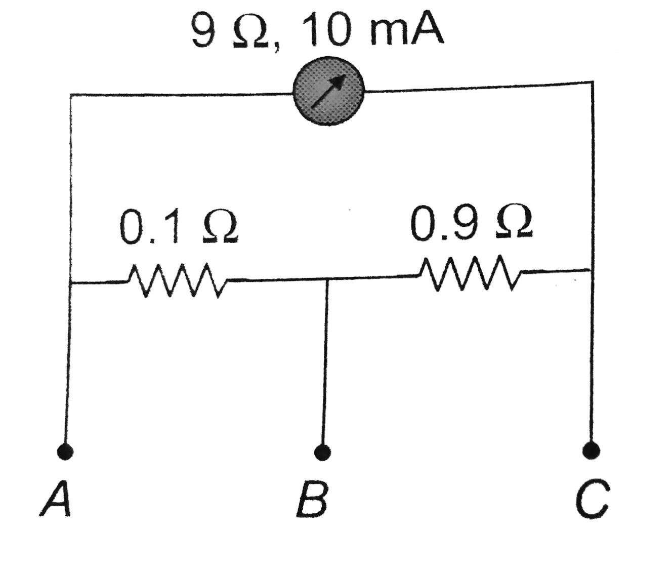
View SolutionA milliammeter of range `10 mA` and resistance `9 Omega` is joined in a circuit as shown. The meter gives full-scale deflection for curretn `I` when `A` and `B` are used as its terminals, i.e., current enters at `A` and leaves at `B` (`C` is left isolated). The value if `I` is
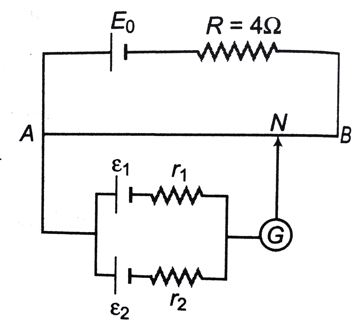
View SolutionA battery of emf `E_0=12V` is connected across a `4 m` long uniform wire having resistance `4Omega//m`. The cell of small emfs `epsilon_1=2V` and `epsilon_2=4V` having internal resistance `2Omega` and `6Omega` respectivley are connected as shown in the figure. If galvanometer shows no diflection at the point `N` the distance of points `N` from the point `A` is equal to
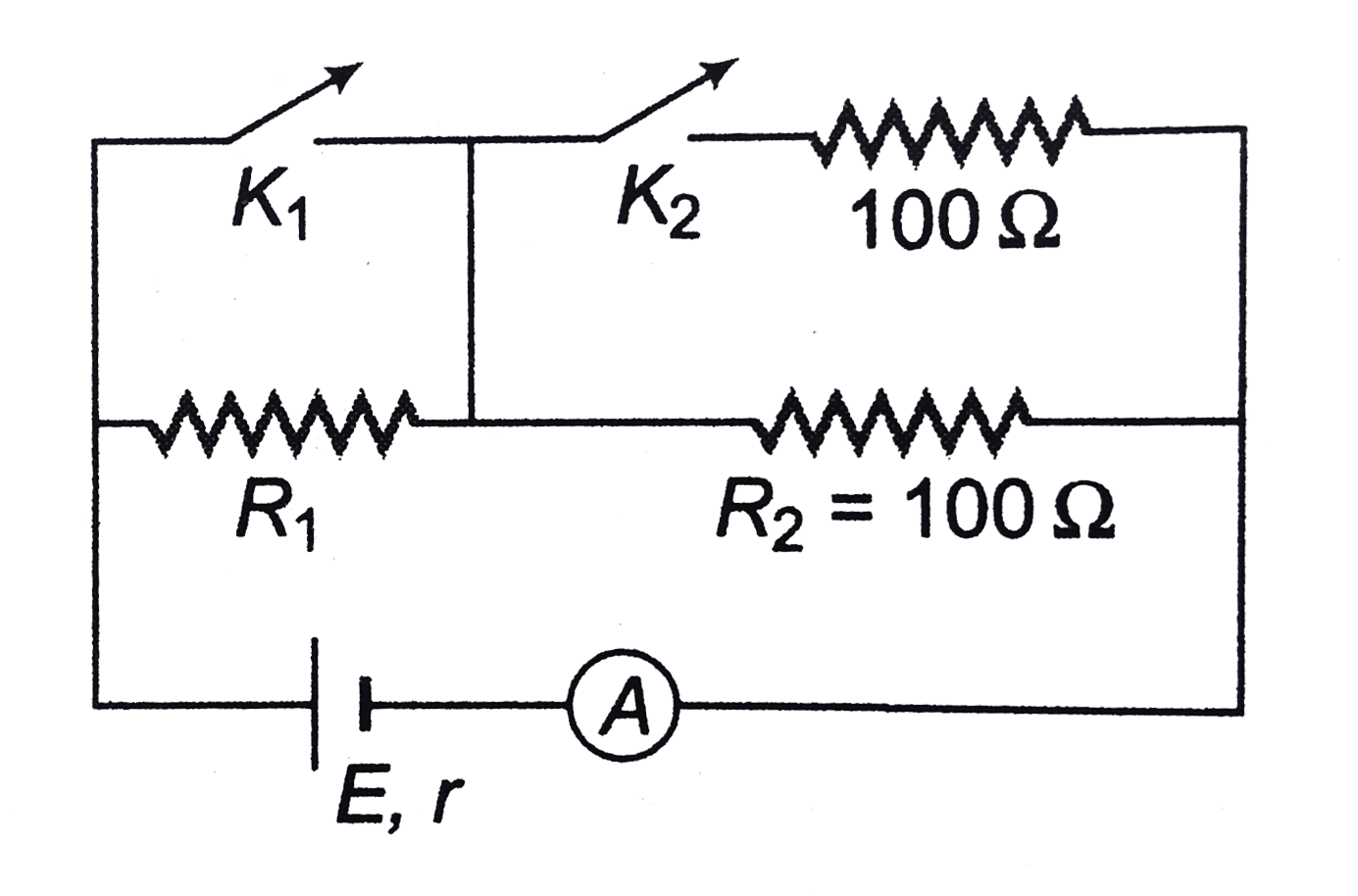
View SolutionIn the circuit shown, keys `K_1` and `K_2` both are closed the ammeter reads `I_0`. But when `K_1`is open and `K_2` is closed, the ammeter reads `I_0//2`. Assuming that ammeter resistance is much less than `R_2`, the values of `r` and `R_1` is Omega are
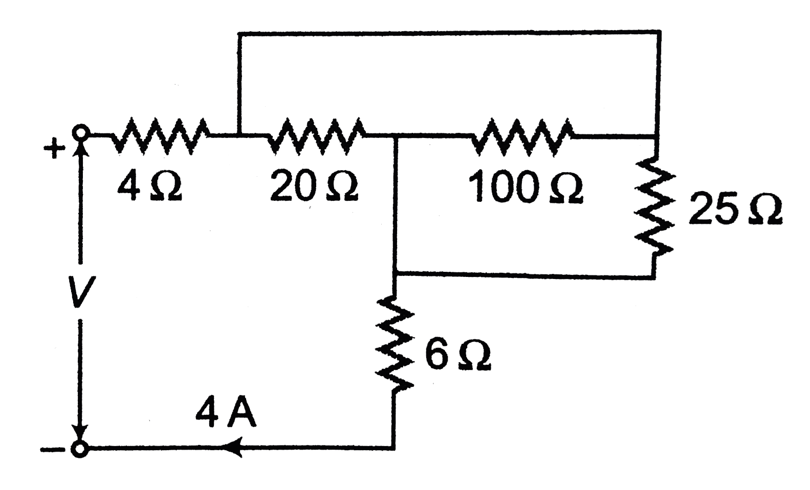
View SolutionIn the circuit shown in figure , `V` must be
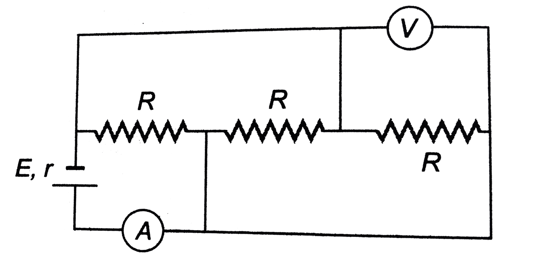
View SolutionIn the circuit shown in figure ammeter and voltmeter are ideal. If `E=4 V,R=9Omega` and `r=1Omega` then readings of ammeter and voltmeter are
View SolutionA moving coil galvnometer is converted into an ammeter reading up to `0.03 A` by connecting a shunt of resistance `r/4`. What is the maximum current which can be sent through this galvanometer if no shunt is used (here r=resistance of galvanometer)
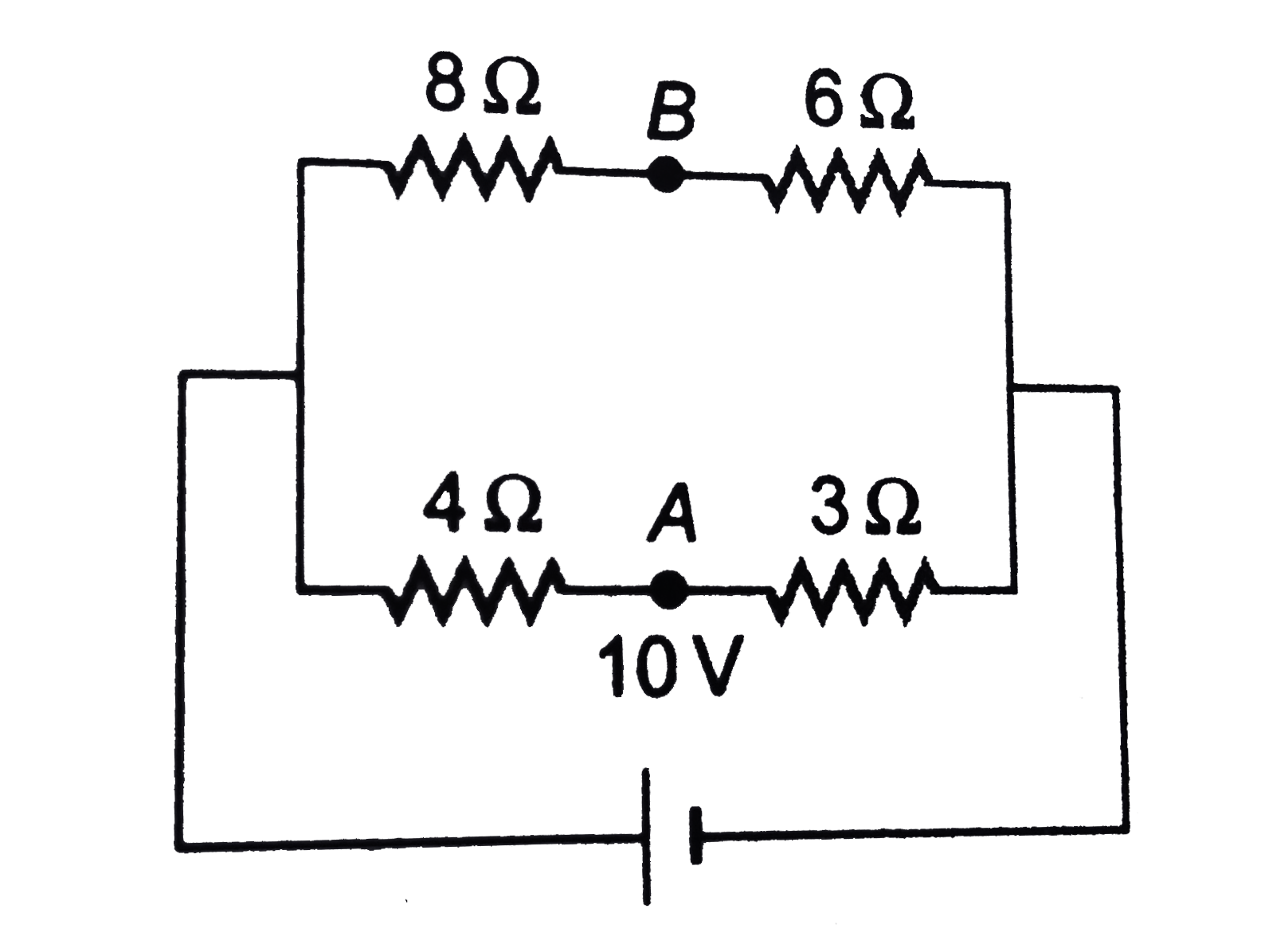
View SolutionThe potential difference between points `A` and `B` is
View SolutionTwo wires `A` and `B` made of same material and having their lengths in the ratio `6:1` are connected in series The potential difference across the wire `3V` and `2V` respectively. If `r_A` and `r_B` are the radii of `A` and `B` respectively, then `r_B/r_A` is
View SolutionA galvanometer of resistance `50 Omega ` is connected to a battery of `3 V` along with resistance of `2950 Omega` in series. A full scale deflection of 30 divisions is obtained in the galvanometer. In order to reduce this deflection to 20 division the above series resistance should be
View SolutionFigure shows a potentiometer arrangement with `R_(AB)=10 Omega` and rheostat of variable resistance d. For `x=0` null deflection point is found at `20 cm` from `A`. For unknown value of `x` null deflection point was at `30 cm` from `A`, then the value of x is
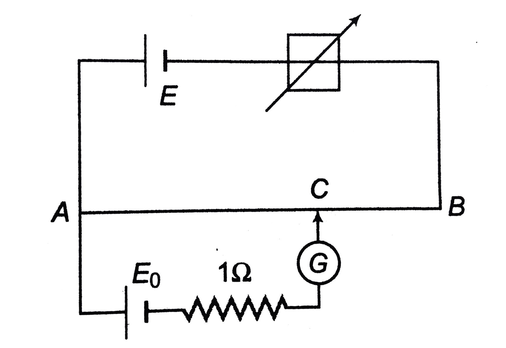
View SolutionIn the given potentiometer arrangemeter the null point
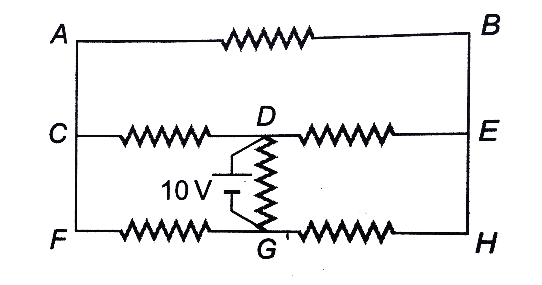
View SolutionAll resistance shown in the circuit are `2Omega` each. The current in the resistance between `D` and `E` is
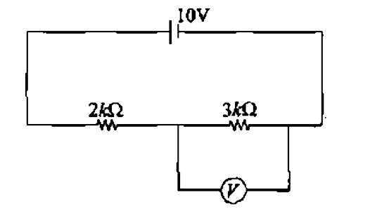
View SolutionIri the circuit shown in figure-3.334, the resistance of voltmeter is` 6kOmega`. The voltmeter reading will be :
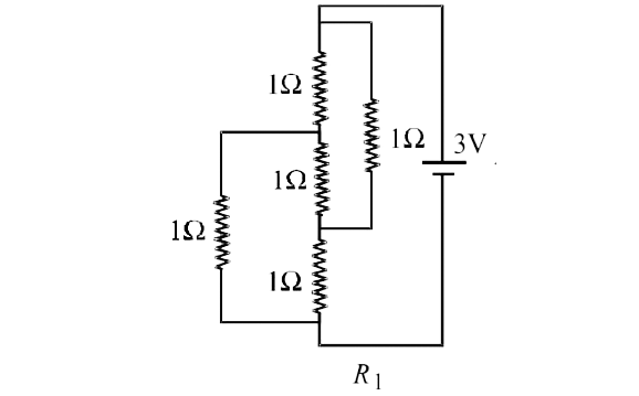
View SolutionFigure shows three resistor configurations `R_1,R_2 and R_3` connected to 3V battery. If the power dissipated by the configuration `R_1,R_2 and R_3` is `P_1, P_2 and P_3`, respectively. Then -
 ,
,  ,
, 
View Solution
Level 2 Single Correct questions and complete solutions for chapter CURRENT ELECTRICITY of DC PANDEY PHYSICS (HINGLISH) of Class 12
All Exercises from DC PANDEY Class 12 PHYSICS CURRENT ELECTRICITY
- B. Assertion and reason
- Check point
- Example
- Example Example Type
- Example Type 1
- Example Type 2
- Example Type 3
- Example Type 4
- Example Type 5
- Example Type 6
- Exercise 23.1
- Exercise 23.10
- Exercise 23.11
- Exercise 23.12
- Exercise 23.13
- Exercise 23.2
- Exercise 23.3
- Exercise 23.4
- Exercise 23.5
- Exercise 23.6
- Exercise 23.7
- Exercise 23.8
- Exercise 23.9
- Level 1 Assertion And Reason
- Level 1 Objective
- Level 1 Subjective
- Level 2 Comprehension Example Type
- Level 2 More Than One Correct
- Level 2 Single Correct
- Level 2 Subjective
- Match the columns
- Medical entrances gallery
- Miscellaneous Examples
- OBJECTIVE_TYPE
- Taking it together