Complete Solutions to Taking it together of chapter ELECTROMAGNETIC INDUCTION of Class 12 book with complete answers and questions
| Class 12 | PHYSICS |
| Chapter | ELECTROMAGNETIC INDUCTION |
| DC PANDEY NEET | Taking it together |
| Number Of Questions | 100 |
| Academic Year | 2023-24 |
L, C and R represent the physical quantities, inductance, capacitance and resistance respectively. The combination(s) which have the dimensions of frequency are
View SolutionThe self inductance L of a solenoid of length l and area of cross-section A, with a fixed number of turns N increases as
View SolutionIn electromagnetic induction, the induced charge in a coil is independent of
View SolutionA coil and a bulb are connected in series with a `dc` source, a soft iron core is then inserted in the coil. Then
View SolutionA magnet is brought towards a coil (i) speedily (ii) slowly then the induced e.m.f.//induced charge will be respectively
View SolutionA coil of area `10cm^2` and 10 turns is in magnetic field directed perpendicular to the plane and changing at a rate of `10^8 gauss//s`. The resistance of coil is `20Omega`. The current in the coil will be
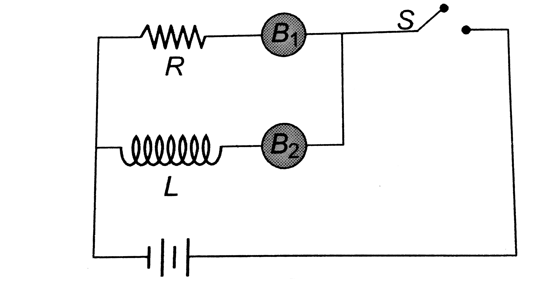
View SolutionThe adjoining figure shows two bulbs `B_(1)` and `B_(2)` resistor `R` and an inductor and `L`. When the switch `S` is turned off
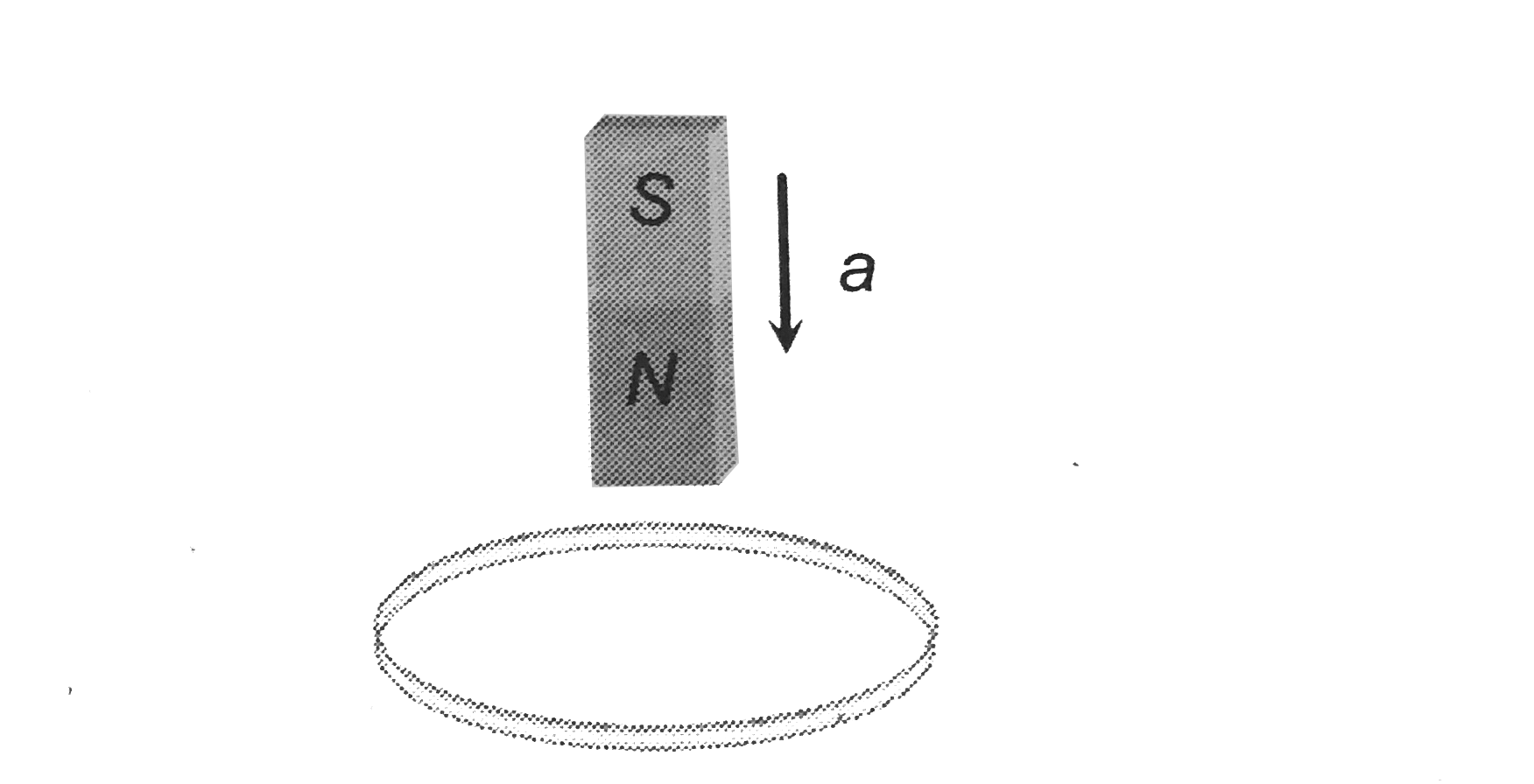
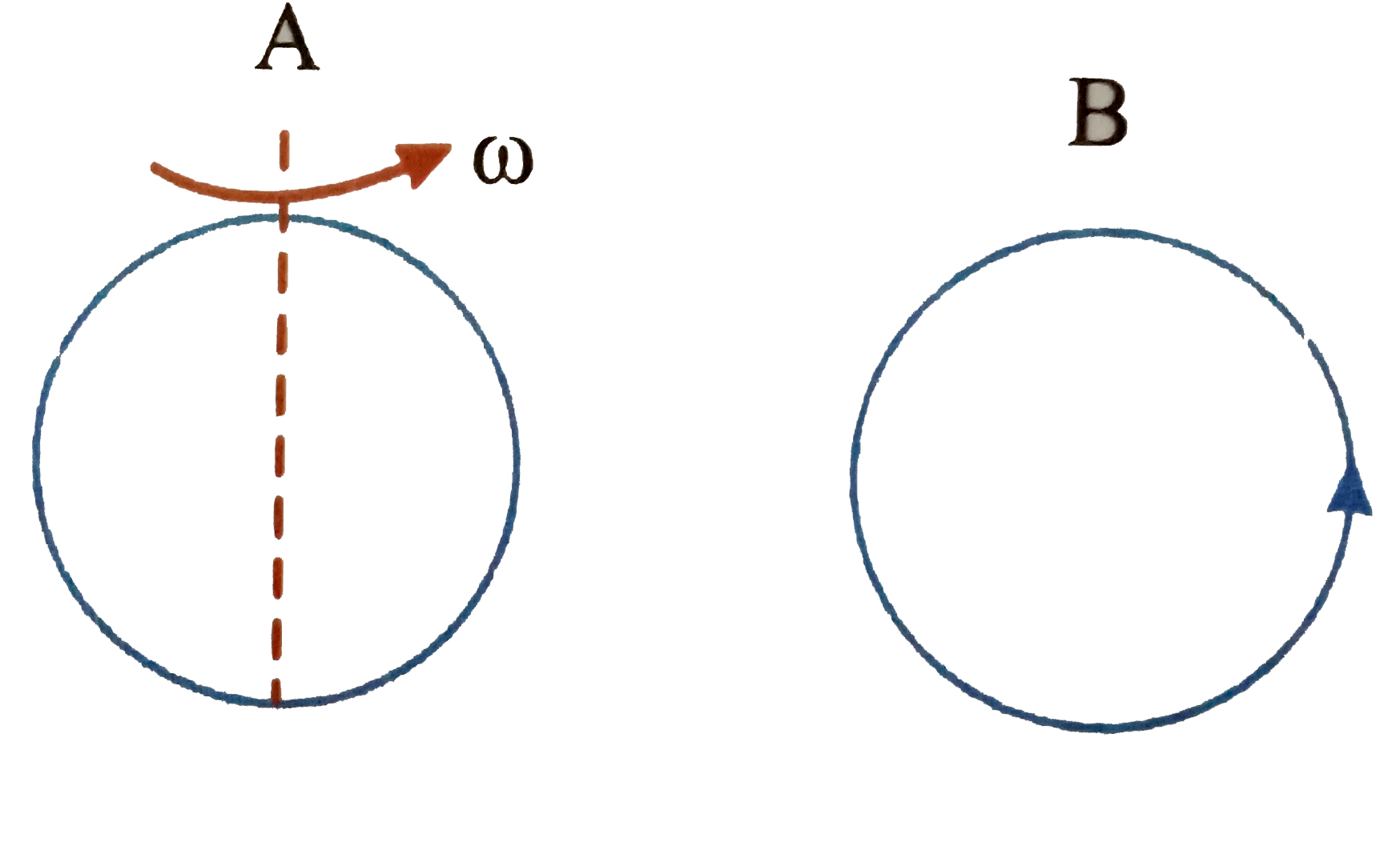
View SolutionTwo identical circular loops of metal wire are lying on a table without touching each other. Loop-A carries a current which increases with time. In response, the loop-B
View SolutionA coil having `500` square loops each of side `10 cm` is placed normal to a magnetic flux which increase at the rate of `1.0 "tesla"/"second"`. The induced r.m.f. in volts is
View SolutionA coil having an area `2m^(2)` is placed in a magnetic field which changes from `1 Wb//m^(2)` to `4Wb//m^(2)` in an interval of `2` second. The average e.m.f. induced in the coil will be
View SolutionTwo circular loops of equal radii are placed coaxially at some separation. The first is cut and a battery is inserted in between to drive a current in it. The current changes slightly because of the variation in resistance with temperature. Durig this period, the two loops
View SolutionA small, conducting circular loop is placed inside a long solenoid carrying a current. The plane of the loop contains the axis of the solenoid. If the current in the solenoid is varied, the current induced in the loop is
View SolutionA metallic ring is attached with the wall of a room. When the north pole of a magnet is brought near to it, the induced current in the ring will be
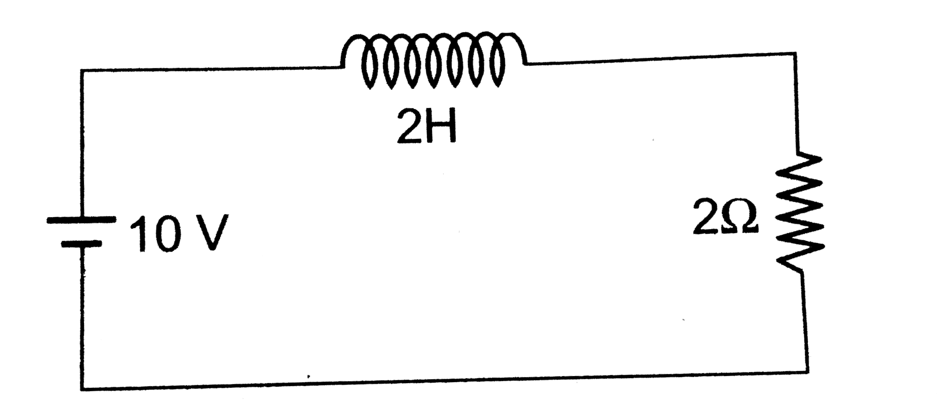
View SolutionIn the figure magnetic energy stored in the coil is
View SolutionAn emf of `15 V` is applied in a circuit containing `5 H` inductance and `10 Omega` resistance. The ratio of the currents at time `t = oo` and `t = 1 s` is
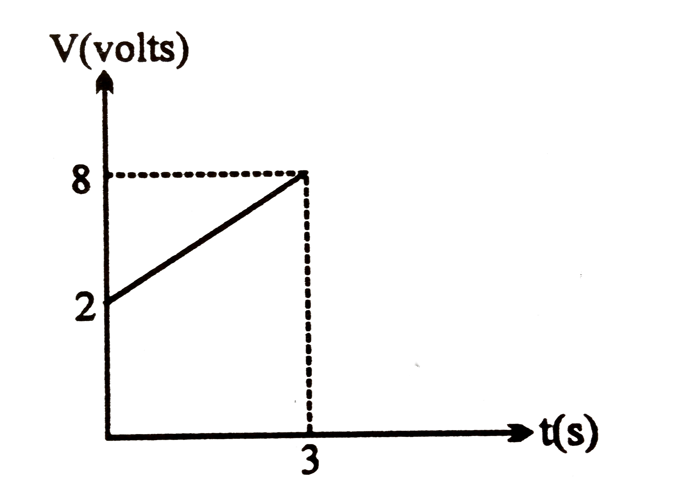
View SolutionA circuit element is placed in a closed box. At time t=0, constant current generator supplying a current of 1 amp, is connected across the box. Potential difference across the box varies according to graph shown in figure. The element in the box is:
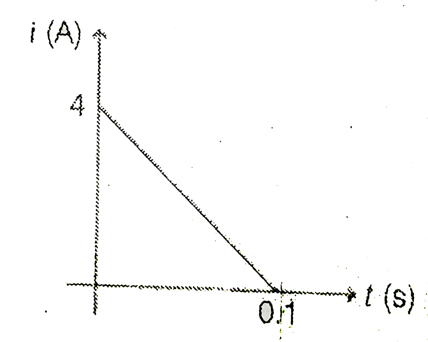
View SolutionSome magnetic flux is changed from a coil resistance `10Omega`. As a result an induced current developed in it. Which varies with time as shown figure, The magnitude of changes f in flux through the coil (in webers) is
View SolutionThe adjoining figure shows two bulbs `B_(1)` and `B_(2)` resistor `R` and an inductor and `L`. When the switch `S` is turned off

View SolutionA coil of `40 Omega` resistance has `100` turns and radius `6 mm` us connected to ammeter of resistance of `160 ohms`. Coil is placed perpendicular to the magnetic field. When coil is taken out of the field, `32 mu C` charge flows through it. The intensity of magnetic field will be
View SolutionA coil has an area of `0.05 m^(2)` and it has `800` turns. It is placed perpendicular in a magnitude field of strength `4xx10^(-5)Wb//m^(2)`, it is rotated through `90^(@)` in `0.1` sec. the average e.m.f. induced in the coil is
View SolutionIn a magnetic field of `0.05T`, area of a coil changes from `101 cm^(2)` to `100 cm^(2)` without changing the resistance which is `2Omega`. The amount of charge that flow during this period is
View Solutionthe resistance and inductance of series circuit are `5Omega` and `20H` respectively. At the instant of closing the switch, the current is increasing at the rate `4A-s`. The supply voltage is
View SolutionThe number of turns in the coil of an ac genrator is `5000` and the area of the coil is `0.25m^(2)`. The coil is rotate at the rate of `100 "cycles"//"sec"` in a magnetic field of `0.2W//m^(2)`. The peak value of the emf generated is nearly
View SolutionA wheel with ten metallic spokes each `0.50 m` long is rotated with a speed of `120 rev//min` in a plane normal to the earth's magnetic field at the place. If the magnitude of the field is `0.4` gauss, the induced e.m.f. between the axle and the rim of the wheel is equal to
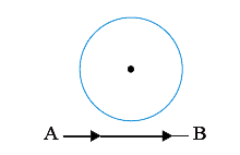
View SolutionA charge particle moves along the line AB, which lies in the same plane of a circular loop of conduting wire as shown in the fig . Then :
View SolutionAn electric potential difference will be induced between the ends of the conductor shown in the diagram when it moves in the direction

View SolutionA long horizontal metallic rod with length along the east-west direction is falling under gravity. The potential difference between its two ends will
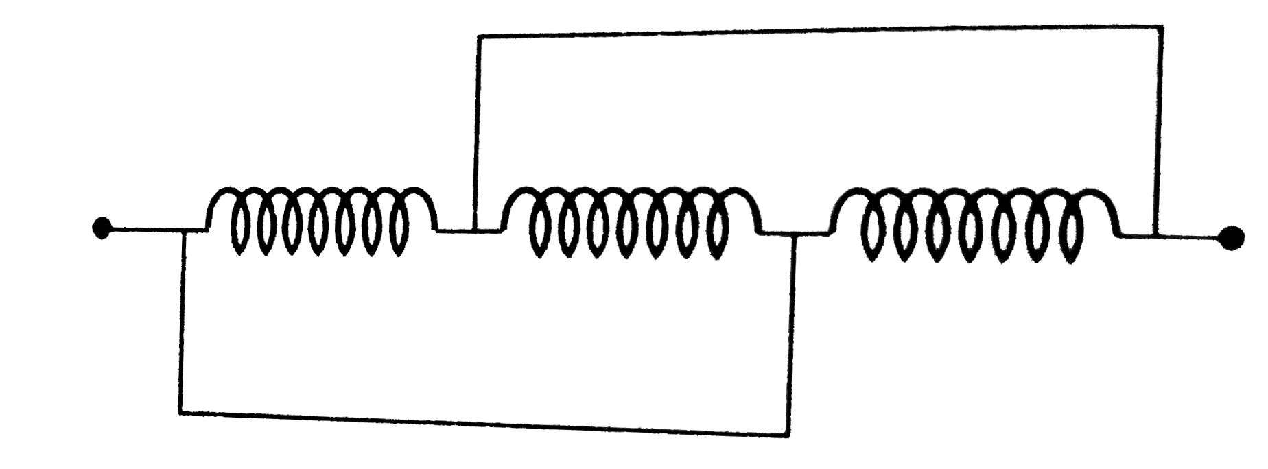
View SolutionPure inductance of `3.0 H` is connected as shown below. The equivalent inductance of the circuit is
View SolutionTwo inductances connected in parallel are equivalent to a single inductance of `1.5H` and when connected in series are equivalent to a single inductance of 0.8 H. The difference in their inductance is
View SolutionAn inductance `L` and a resistance `R` are first connected to a battery. After some time the battery is disconnected but `L` and `R` remain connected in a closed circuit. Then the current reduces to `37%` of its initial value in
View SolutionThe time constant of an inductance coil is `2 xx 10^(-3) s`. When a `90 Omega` resistance is joined in series, the same constant becomes `0.5 xx 10^(-3) s`. The inductance and resistance of the coil are
View SolutionIn the circuit shown , what is the energy stored in the coil at steady state?
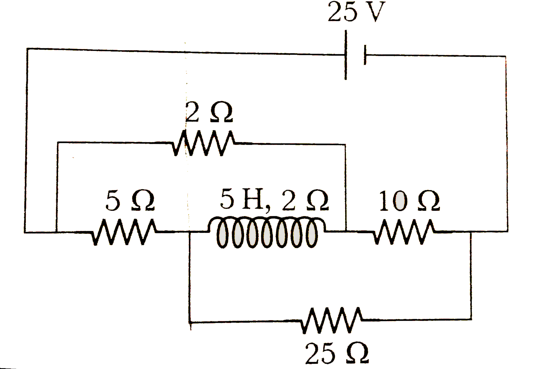
View SolutionIn the following figure, what is the final value of current in the `10 Omega` resistance when the plug of key K is inserted?
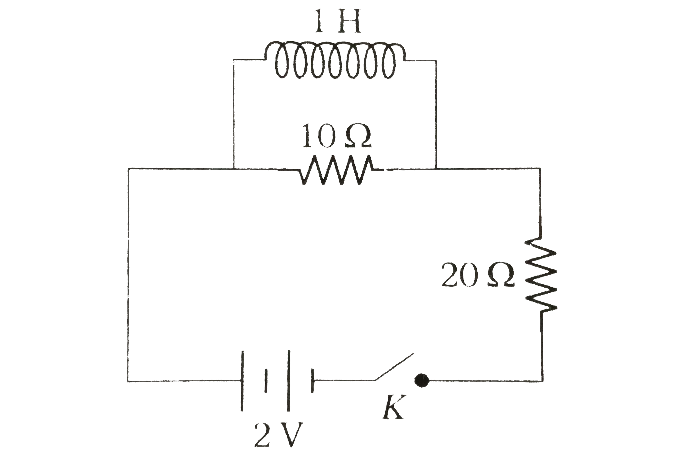
View SolutionA square loop of side L, resistance R placed in a uniform magnetic field B acting normally to the plane of the loop. If we attempt to pull it out of the field with a constant velocity v, then the power needed is
View SolutionA square of side L meters lies in the x-y plane in a region, where the magnetic field is give by `B = B_(0) (2 hati + 3 hat j + 4 hatk)`T, where `B_(0)` is constant. The magnitude of flux passing through the square is
View SolutionA conducting looop of area `5.0cm^(2)` is placed in a magnetic field which varies sinusoidally with time as `B=0.2sin300t` . The normal to the coil makes an angle of `60^(@)` with the field. The emf induced at `t=(pi//900)s`
View SolutionAn infinitely long cylinder is kept parallel to an uniform magnetic field B directed along positive z-axis. The direction of induced current as seen from the z-axis will be
View SolutionA rectangular coil is placed in a region having a uniform magnetic field `B` perpendicular to the plane of the coil. An emf will not be induced ion the coil if the
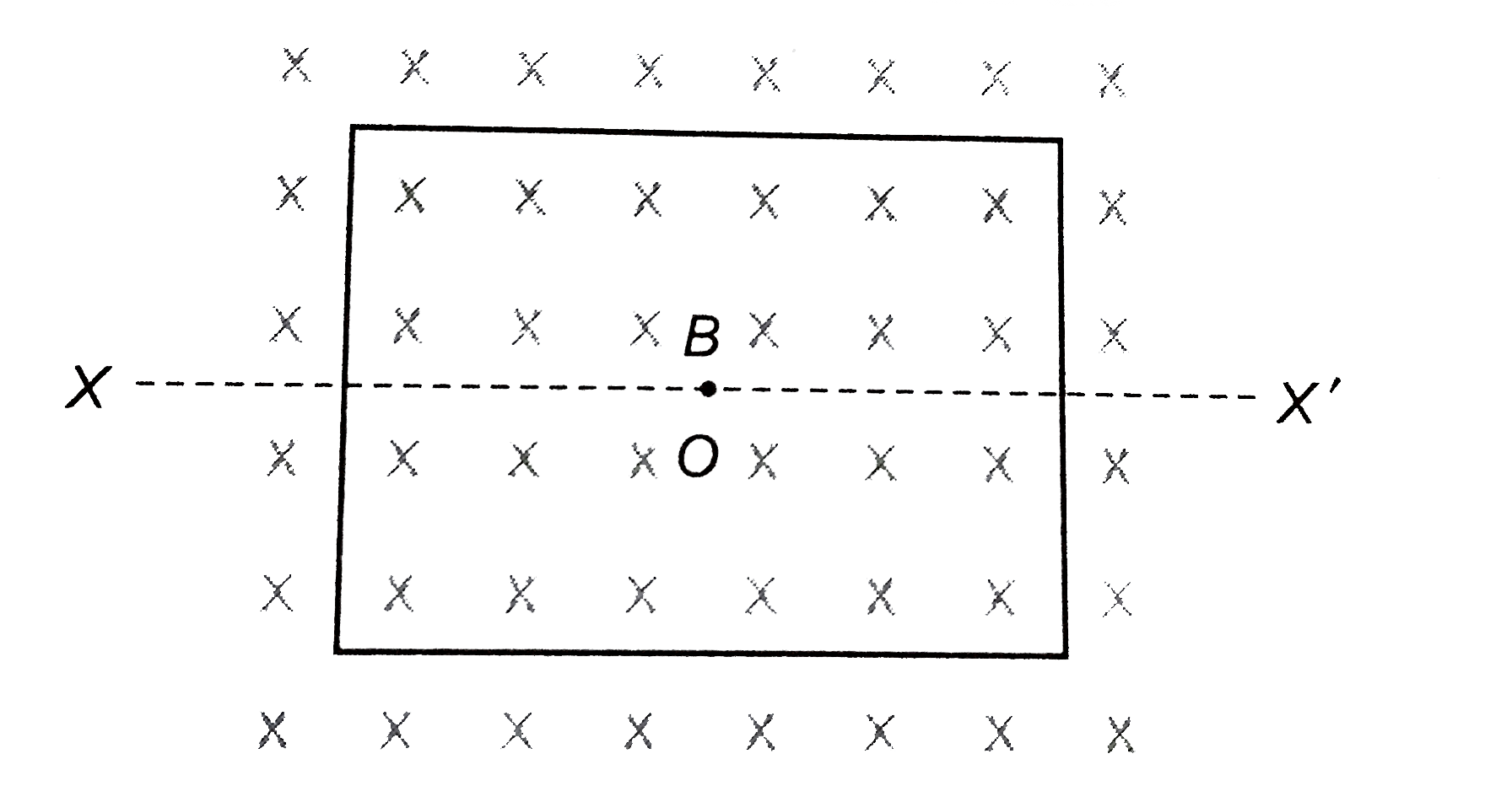
View SolutionIf a coil of `40` turns and area `4.0 cm^(2)` is suddenly remove from a magnetic field, it is observed that a charge of `2.0xx10^(-4)C` flows into the coil. If the resistance of the coil is `80Omega`, the magnetic flux density in `Wb//m^(2)` is
View SolutionA coil of wire of a certain radius has `600` turns and a self-inductance of `108 mH`. The self-inductance of a `2^(nd)` similar coil of `500` turns will be
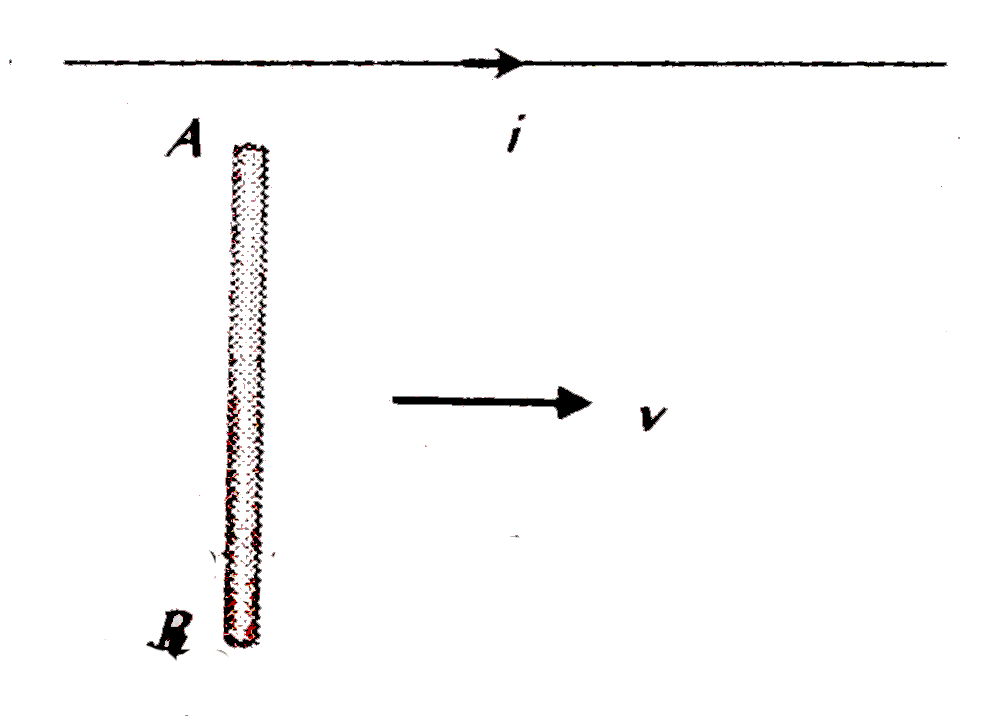
View SolutionThe current carrying wire and the rod AB are in the same plane. The rod moves parallel to the wire with a velocity v . Which one of the following statements is true about induced emf in the rod
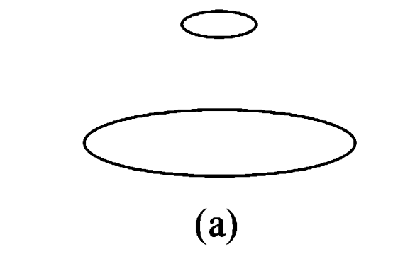
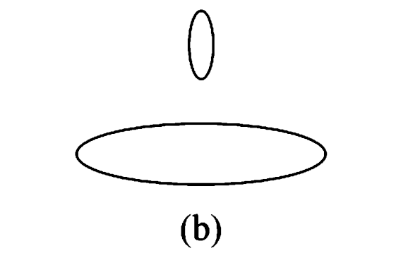
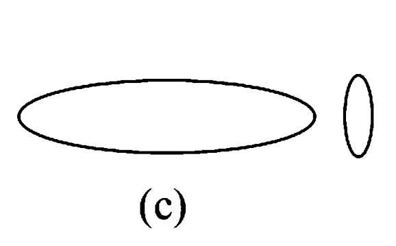
View SolutionTwo circular coils can be arranged in any of the three situation shown in the figure. Their mutual inductance will be
 ,
,  ,
, 
View SolutionA coil of inductance `300mh` and resistance `2Omega` is connected to a source of voltage `2V`. The current reaches half of its steady state value in
View SolutionAn inductor of 2 H and a resitance of `10Omega` are conncts in series with a bttery of 5 V. The intial rate of change of current is
View SolutionIn the circuit shown in the figure, what is the value of `I_(1)` just after pressing the key K?
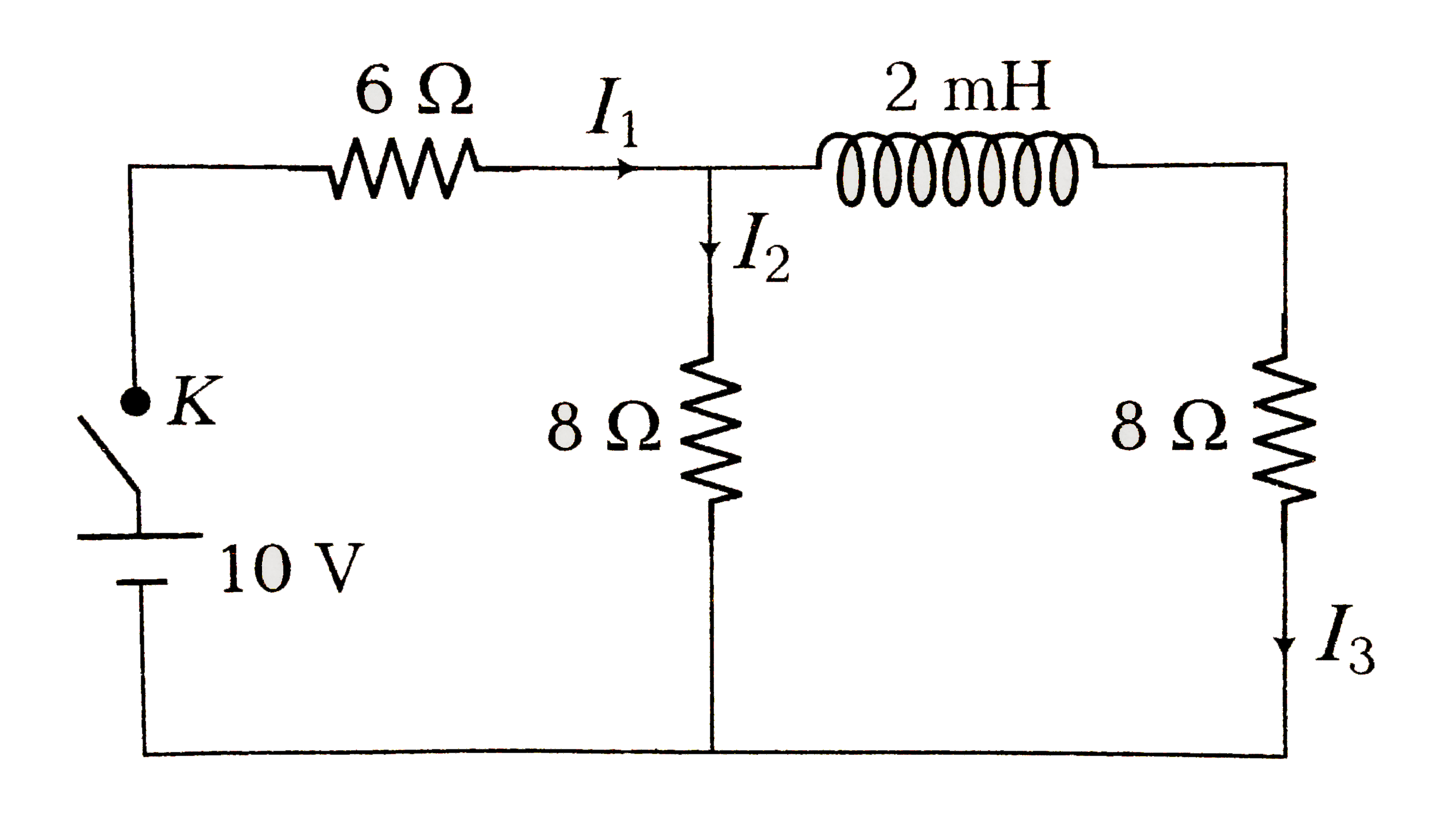
View SolutionIn the circuit shown in Fig. current through the battery at `t = 0` and `t = oo` is
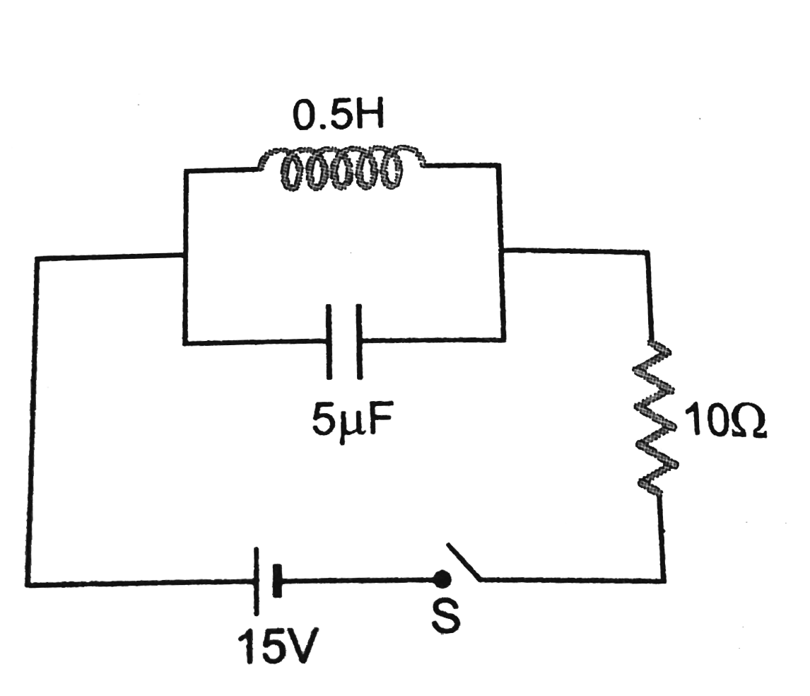
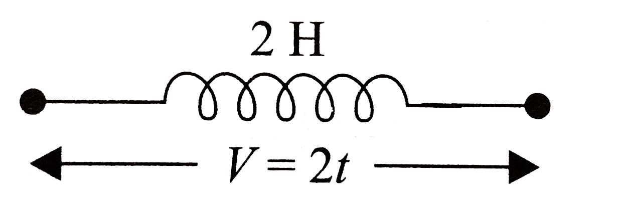
View SolutionA time varying voltage V= 2t (Volt) is applied across and ideal inductor of inductance L =2H as shown in Fig. Then (assume current to be zero at t =0)
View SolutionThe network shown in the figure is part of a complete circuit. If at a certain instant, the current `I` is `5A` and is decreasing at a rate `10^(3)A//s` then `V_(B)-V_(A)` is
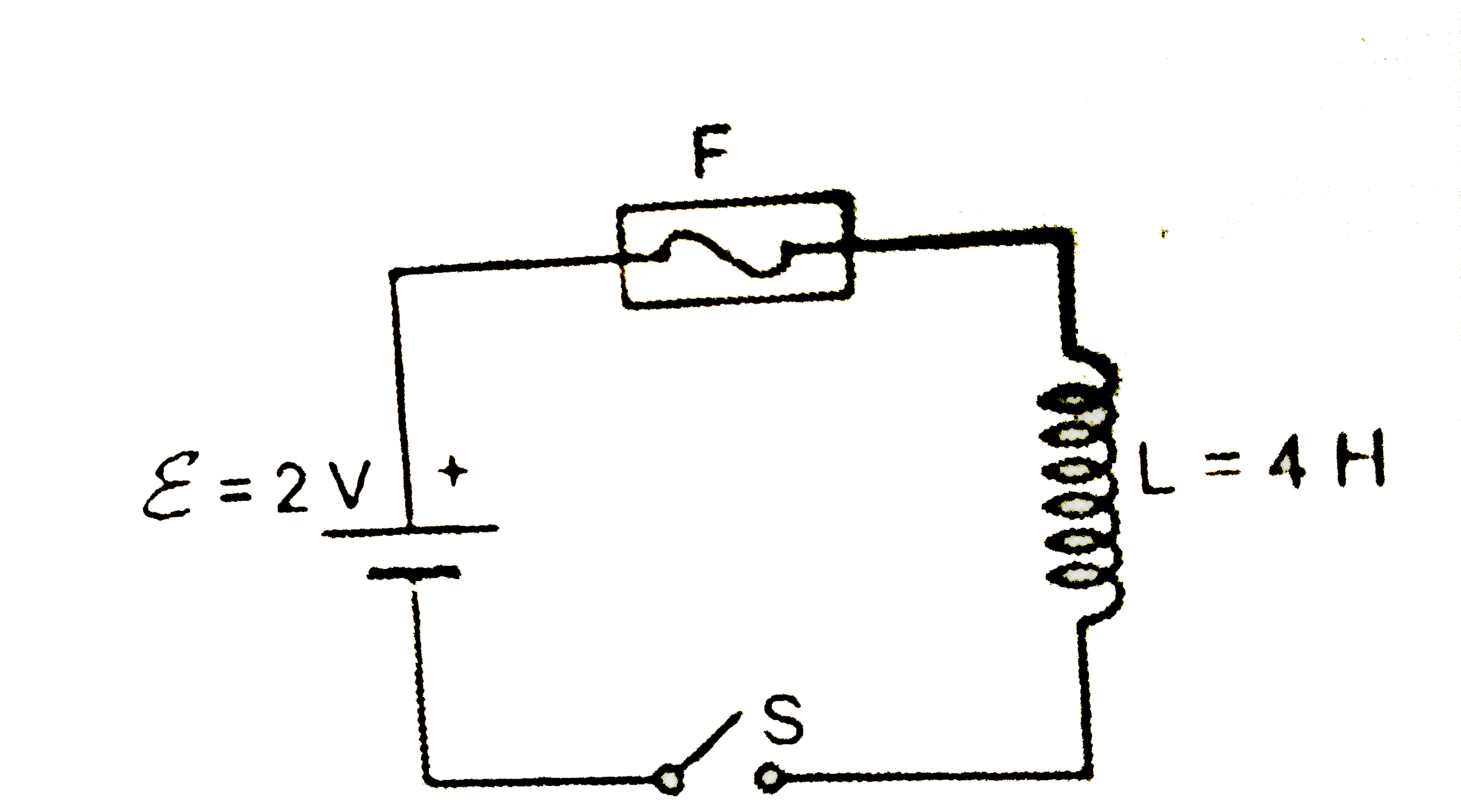
View SolutionSwitch `S` of the circuit shows in Fig is closed at `t = 0`. If `e` denotes the induced emf in `L` and `I` is the current flowing through the circuit at time `t`, which of the following graphs is//are correct?

View SolutionCoefficient of coupling between two coils of self-inductances `L_(1)` and `L_(2)` is unity. It means
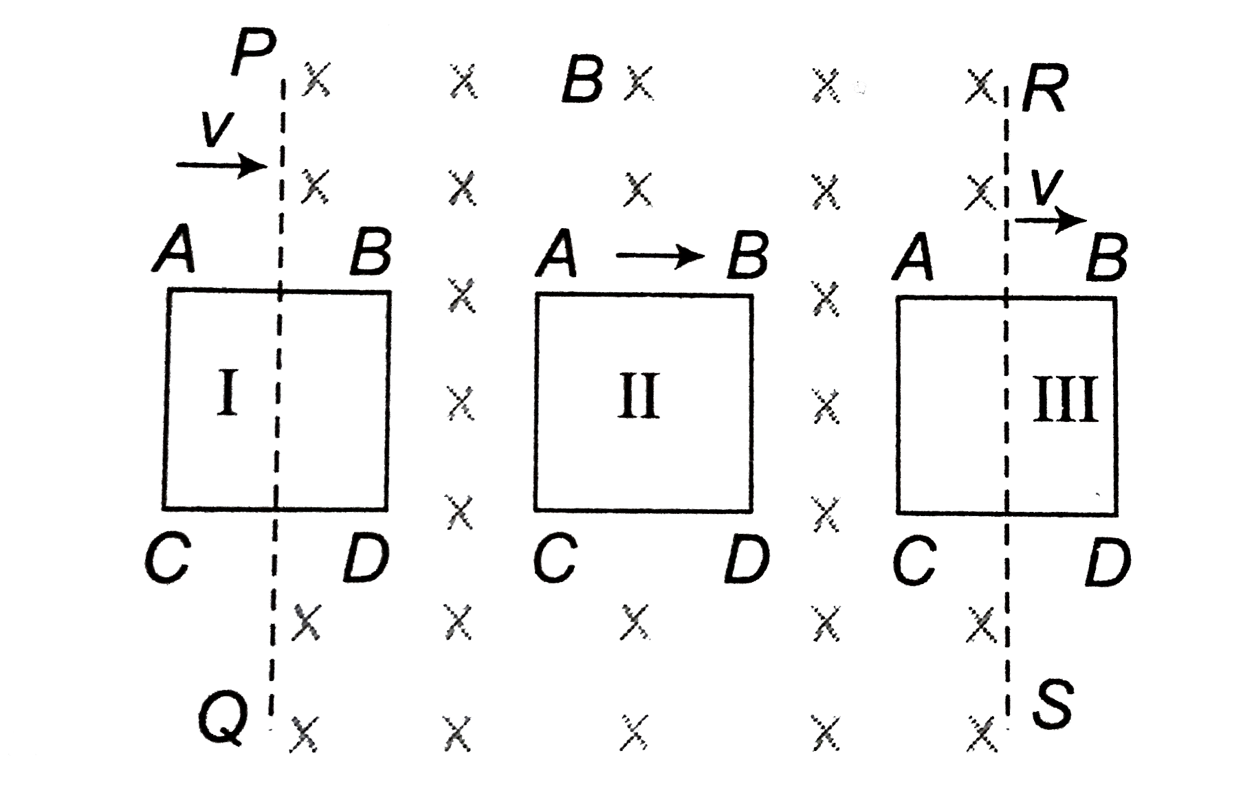
View SolutionA square loop `ABCD` of edge a moves to the right with a velocity `v` parallel to `AB` . There is a uniform magnetic field of magnitude `B` , direction into the paper, in the region between `PQ` and `RS` only. I, II and III are three ppositions of the loop.
(i) The emf induced in the loop has magnitude `B` a `v` in all three position
(iii) Induced emf is anticlockwise in position II
(iv) The induced emf is clockwise in position III
View SolutionA rectangular, a square , a circular and an elliptical loop, all in the `(x-y)` plane, are moving out of a uniform magnetic field with a constant velocity `vec(v)=vhati` . The magnetic field is directed along the negative `z`-axis direction. The induced emf, during the passage of these loops , out of the field region, will not remain constant for :
View SolutionA magnet N-S is suspended from a spring and while at oscillates, the magnet moves in and out of the coil C. The coil is connected to a galvanometer G.
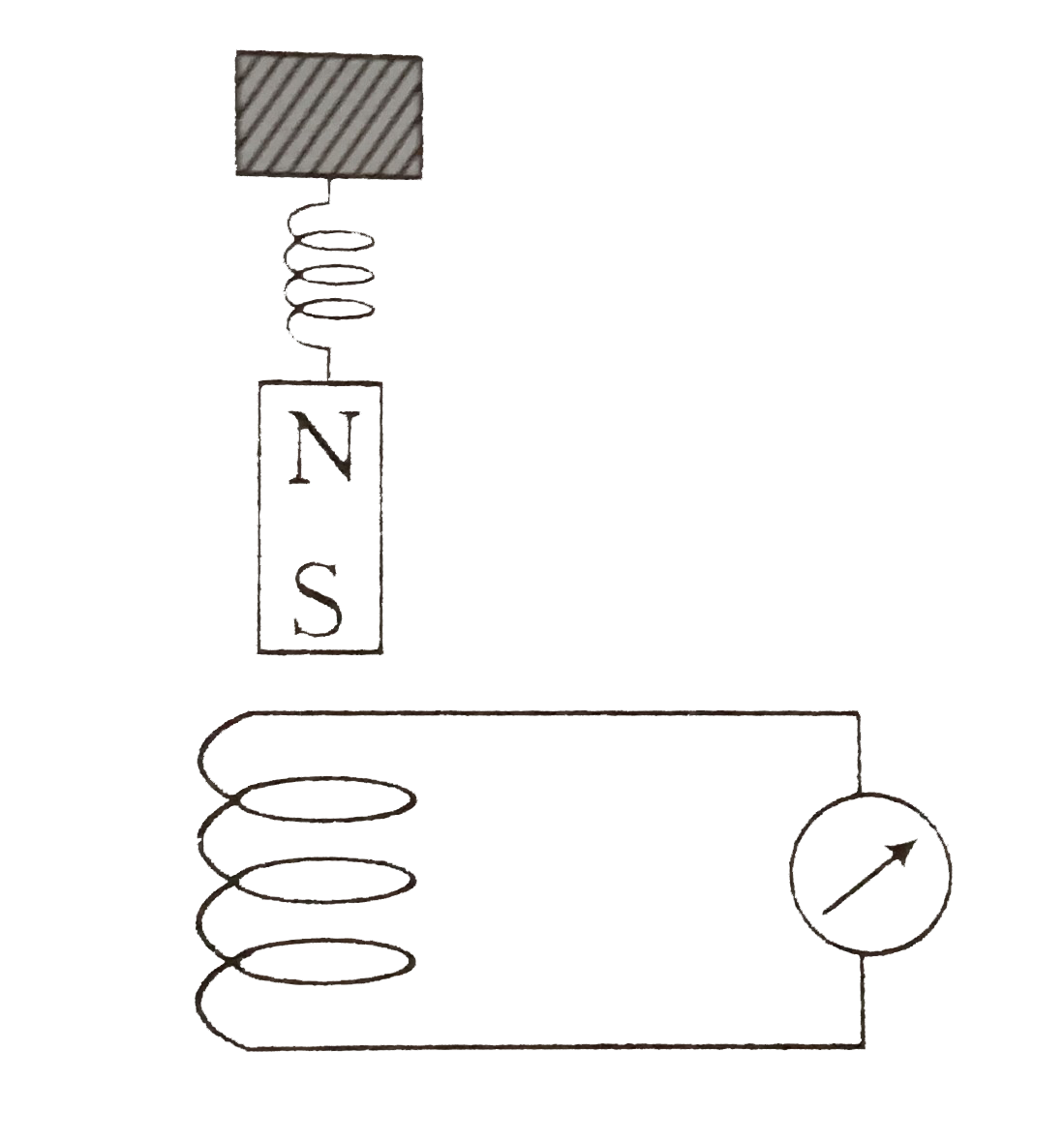
Then, as the magnet oscillates,
View SolutionA coil is suspended in a uniform magnetic field, with the plane of the coil parallel to the magnetic lines of force. When a current is passed through the coil it starts oscillating, It is very difficult to stop. But if an aluminium plate is placed near to the coil, it stops. This is due to :
View SolutionThe conducting circular loops of radii `R_(1) and R_(2)` are placed in the same plane with their centres coinciding. If `R_(1) gt gt R_(2)`, the mutual inductance M between them will be directly proportional to
View SolutionA short-circuited coil is placed in a time-varying magnetic field. Electrical power is dissipated due to the current induced in the coil. If the number of turns were to be quadrupled and the wire radius halved, the electrical power dissipated would be
View SolutionThe variation of induced emf `(E)` with time `(t)` in a coil if a short bar magnet is moved along its axis with a constant velocity is best represent as

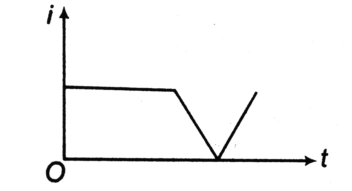
View SolutionThe current i in an inductionn coil varies with time `t` according to the graph shown in the figure. Which of the following grahs shows athe induced emf `(epsilon)` in the coil with time?
View SolutionWhen a battery is connected across a series combination of self inductance L and resistance R , the variation in the current i with time t is best represented by
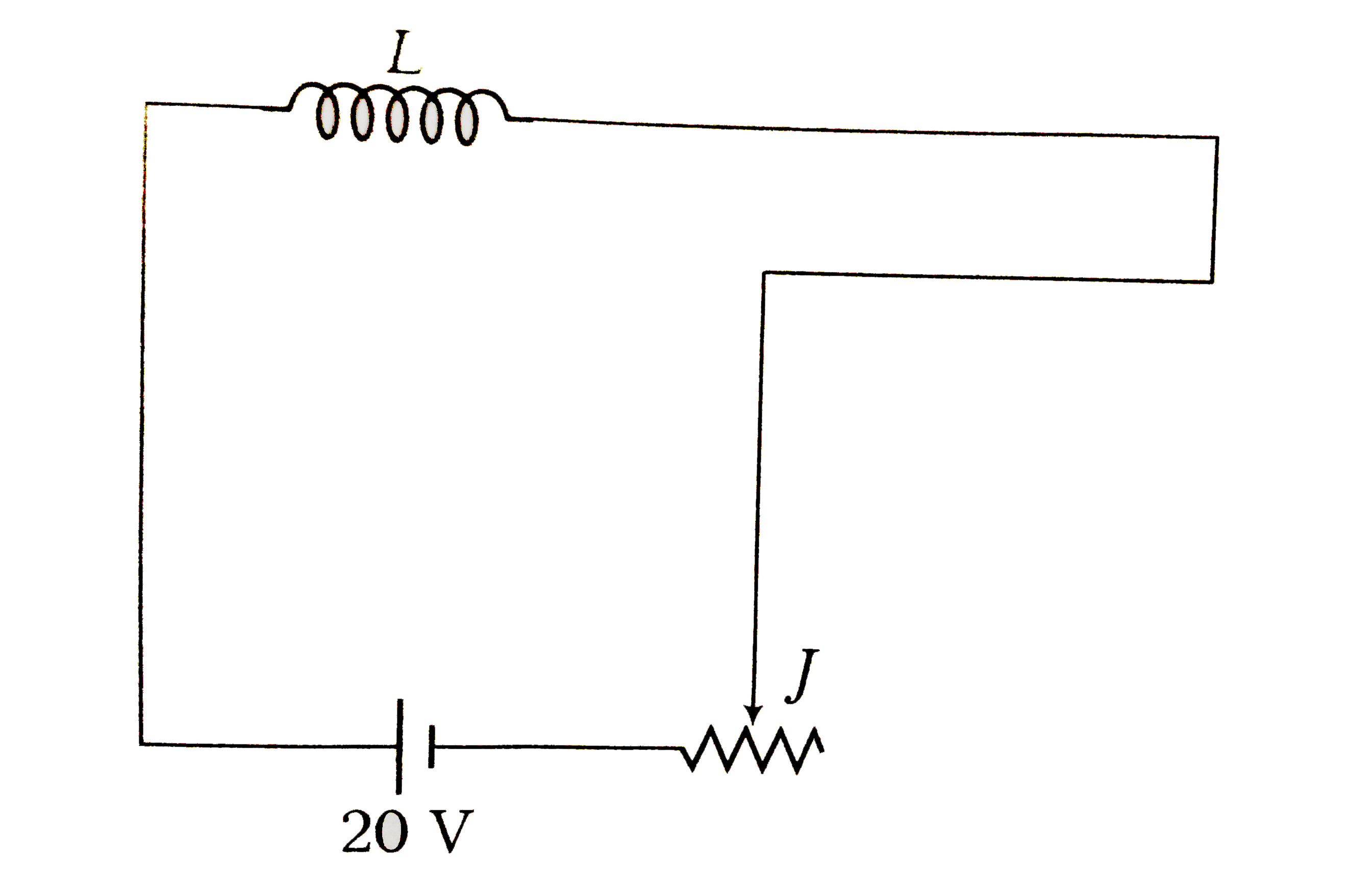
View SolutionIn the circuit shown in the figure, the jockey J is being pulled towards right, so that the resistance in the circuit is increasing. It’s a value at some instant is `5Omega`. The current in the circuit at this instant will be
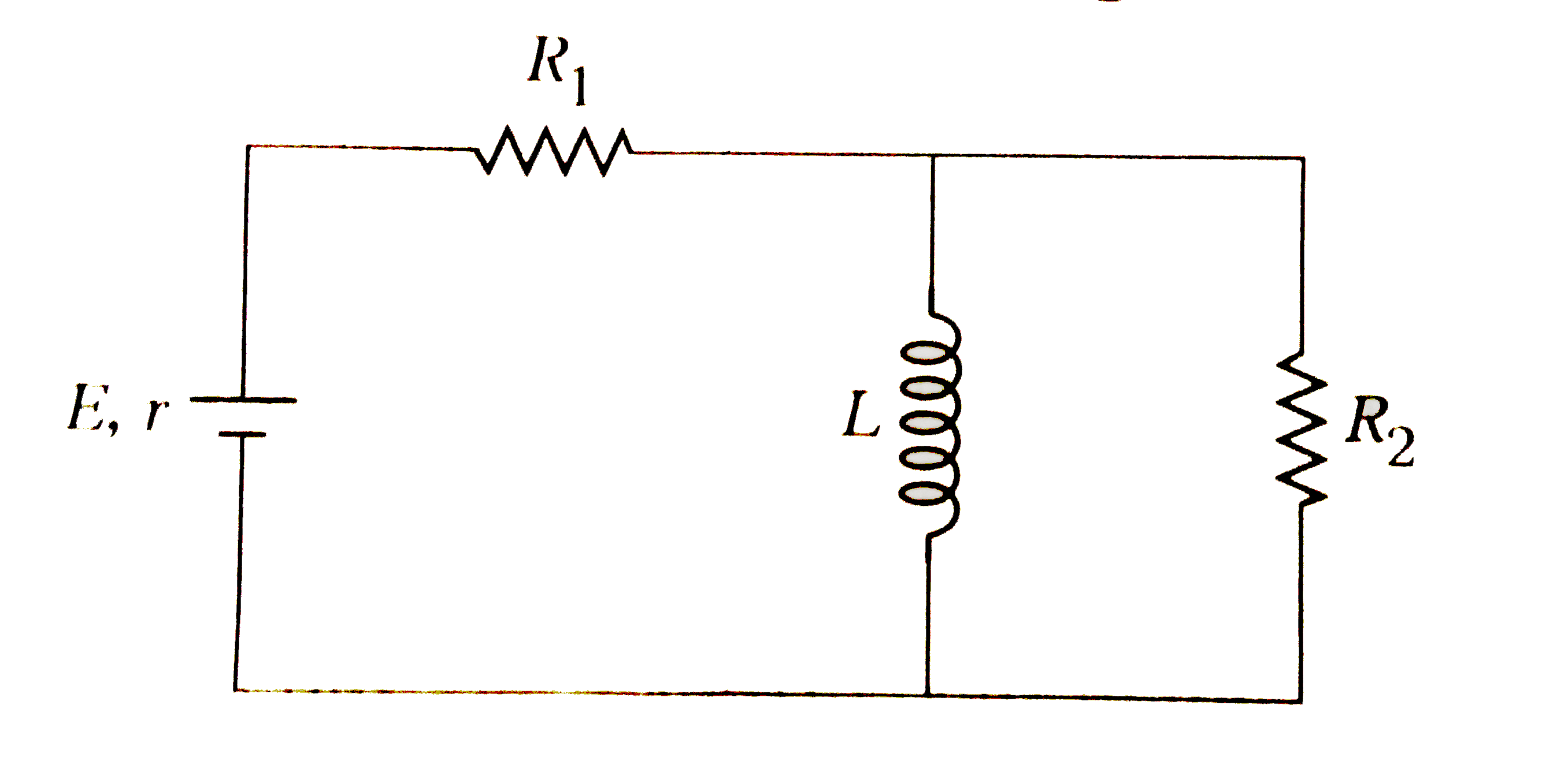
View SolutionThe value of time constant for the given circuit is
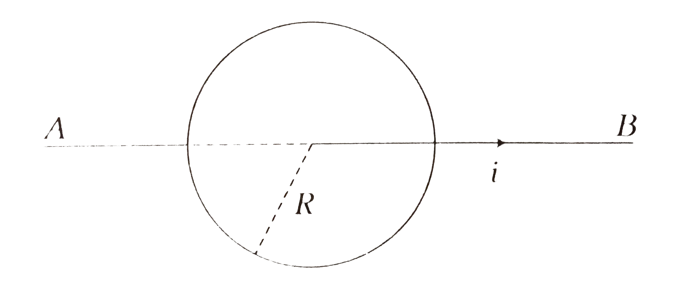
View SolutionA infinitely long conductor AB lies along the axis of a circular loop of radius R. If the current in the conductor AB varies at the rate of x ampere/second, then the induced emf in the loop is
View SolutionA physicist works in a laboratory where the magnetic field is `2T`. She wears a necklace enclosing area `0.01 m^(2)` in such a way that the plane of the necklace is normal to the field and is having a resistance `R=0.01Omega`. Because of power failure, the field decays to `1T` in time `10^(-3)` seconds.
The what is the total heat produced in her necklace?`(T=tesla)`
View SolutionA wheel with ten metallic spokes each `0.50 m` long is rotated with a speed of `120 rev//min` in a plane normal to the earth's magnetic field at the place. If the magnitude of the field is `0.4` gauss, the induced e.m.f. between the axle and the rim of the wheel is equal to
View SolutionAn airplane in which the distance between the tips of wings is `50 m` is flying horizontal with a speed of `360km//hr` over a place where the vertical components of earth magnetic field is `2.0xx10^(-4)webr//m^(2)`. The potential different between the tips of wings would be
View SolutionA conducting square loop of side l and resistance R moves in its plane with a uniform velocity v perpendicular ot one of its sides. A uniform and constant magnetic field B exists along the perpendicualr ot the plane of the loop as shown in . The current induced in the loop is
(##HCV_VOL2_C38_E01_025_Q01##)
View SolutionTwo rails of a railway track, insulated from each other and the ground, are connected to a millivoltmetre. What is the reading of the millivoltmetre when a train travels at a speed of 20 `ms^(-1)` along the track? Given that the vertical component of earth's magnetic field is `0.2xx10^(-4)"Wbm"^(-2)` and the rails are separated by 1 m
View SolutionA Pair of coils of turns `n_(1)` and `n_(2)` are kept close together. Current passing through the first is reduced at r, and emf 3 mV is developed across the other coil. If the second coil carries current which is then reduced at the rate 2 r, the emf produced across the first coil will be
View SolutionA loop made of straight edegs has six corners at `A(0,0,0), B(L, O,0) C(L,L,0), D(0,L,0) E(0,L,L)` and `F(0,0,L)`. Where `L` is in meter. A magnetic field `B = B_(0)(hat(i) + hat(k))T` is present in the region. The flux passing through the loop `ABCDEFA` (in that order) is
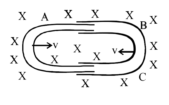
View SolutionOne conducting U tube can slide inside another as shown in figure, maintaining electrical contacts between the tubes. The magnetic field B is perpendicular to the plane of the figure. If each tube maoves towards the other at a constant speed v. Then the emf induced in the circuit in terms of B, l and v where l is the width of each tube will be
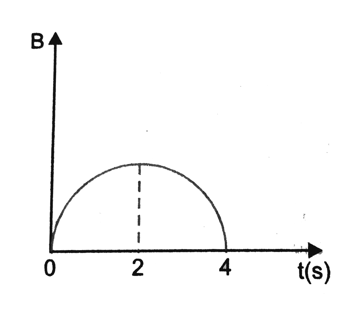
View SolutionIn a closed loop, which has some inductance but negligible resistance, uniform but time varying magentic field is applied directed into the plane of the loop. Variation of field with time is shown in Fig. Initially current in loop was zero. Then .
View SolutionA magnetic field given by B(t) `=0.2t-0.05t^(2)` tesla is directed perpendicular to the plane of a circular coil containing 25 turns of radius 1.8 cm and whose total resistance is `1.5Omega`. The power dissipation at 3 s is approximately
View SolutionA small magnet `M` is allowed to fall through a fixed horizontal conducting ring `R`. Let `g` be the acceleration due to gravity. The acceleration of `M` will be
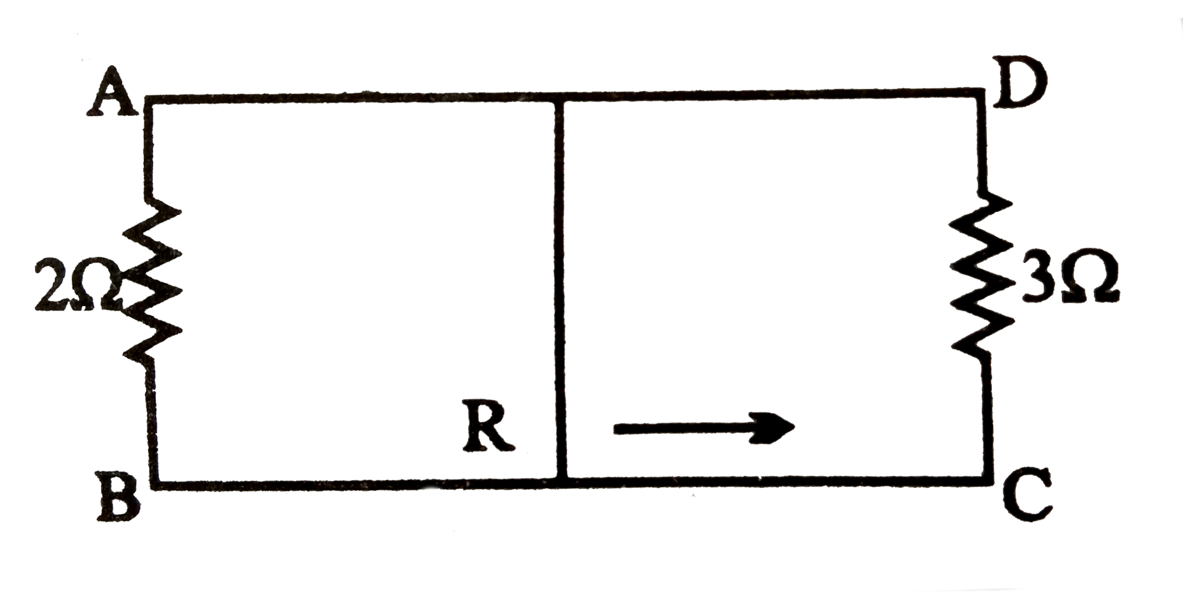
View SolutionA rectangular loop with a sliding connector of length `10 cm` is situated in uniform magnetic field perpendicular to plane of loop. The magnetic induction is `0.1` tesla and resistance of connector `(R )` is `1 ohm`. The sides `AB` and `CD` have resistances `2 ohm` and `3 ohm` respectively. Find the current in the connector during its motion with constant velocity one
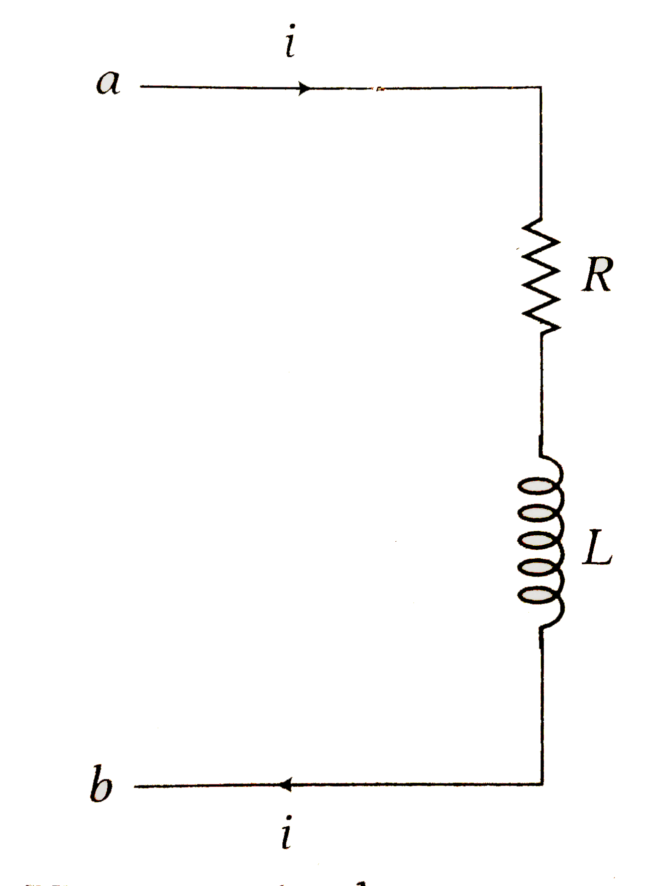
View SolutionWhen the current in the portion of the circuit shown in the figure is 2 A and increasing at the rate of `1As^(-1)`, then the measured potential difference `V_(ab)=8V`.
However, when the current is 2 A and decreasing at the rate of `1As^(-1)`, then the measured potential difference `V_(ab)=4V`.
The values of R and L are
View SolutionTwo different coils have self-inductances `L_(1) = 8 mH and L_(2) = 2 mH`. The current in one coil is increased at a constant rate. The current in the second coil is also increased at the same constant rate. At a certain instant of time, the power given to the two coil is the same. At that time, the current, the induced voltage and the energy stored in the first coil are `i_(1), V_(1) and W_(1)` respectively. Corresponding values for the second coil at the same instant are `i_(2), V_(2) and W_(2)` respectively. Then:
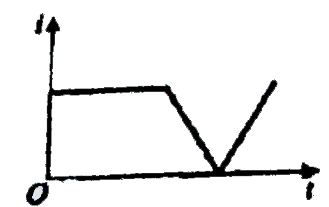
View SolutionThe current i in an induction coil varies with time t according to the graph shown in the figure-5.250. Which of the following graphs shows the induced EMF in the coil with time ?
View SolutionA coil of inductance `L=50muH` and resistance = `0.5Omega` is connected to a battery of emf = 5V.
A resistance of `10Omega` is connected parallel to the coil. Now, at the same instant the connection of the battery is switched off. Then, the amount of heat generated in the coil after switching off the battery is
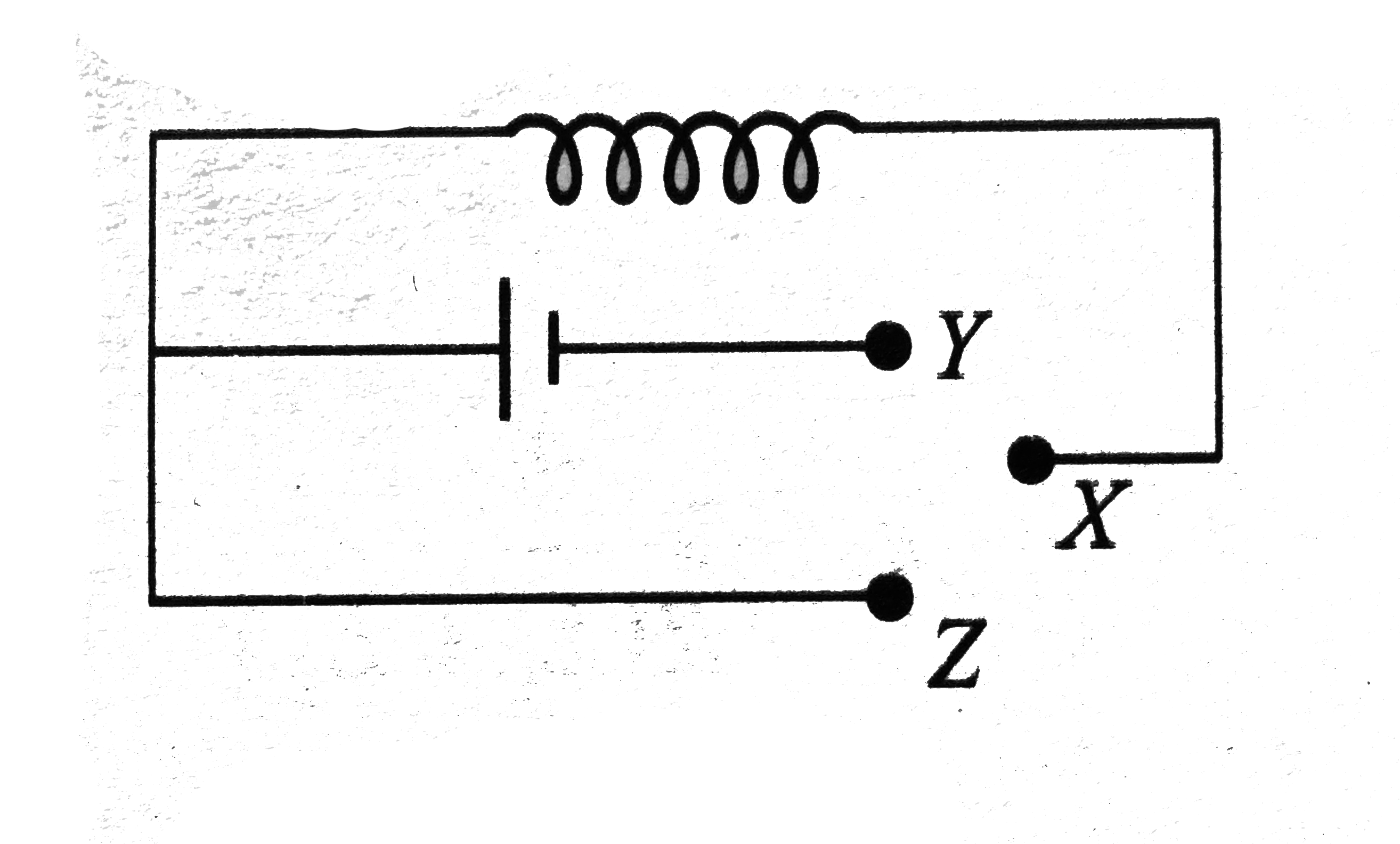
View SolutionIn the circuit shows in Fig, the coil has inductance and resistance. When `X` is joined to `Y`, the time constant is `tau` during the growth of current. When the steady state is reached, heat is produced in the coil at a rate `P`. `X` is now joined to `Z`. After joining `X` and `Z`:
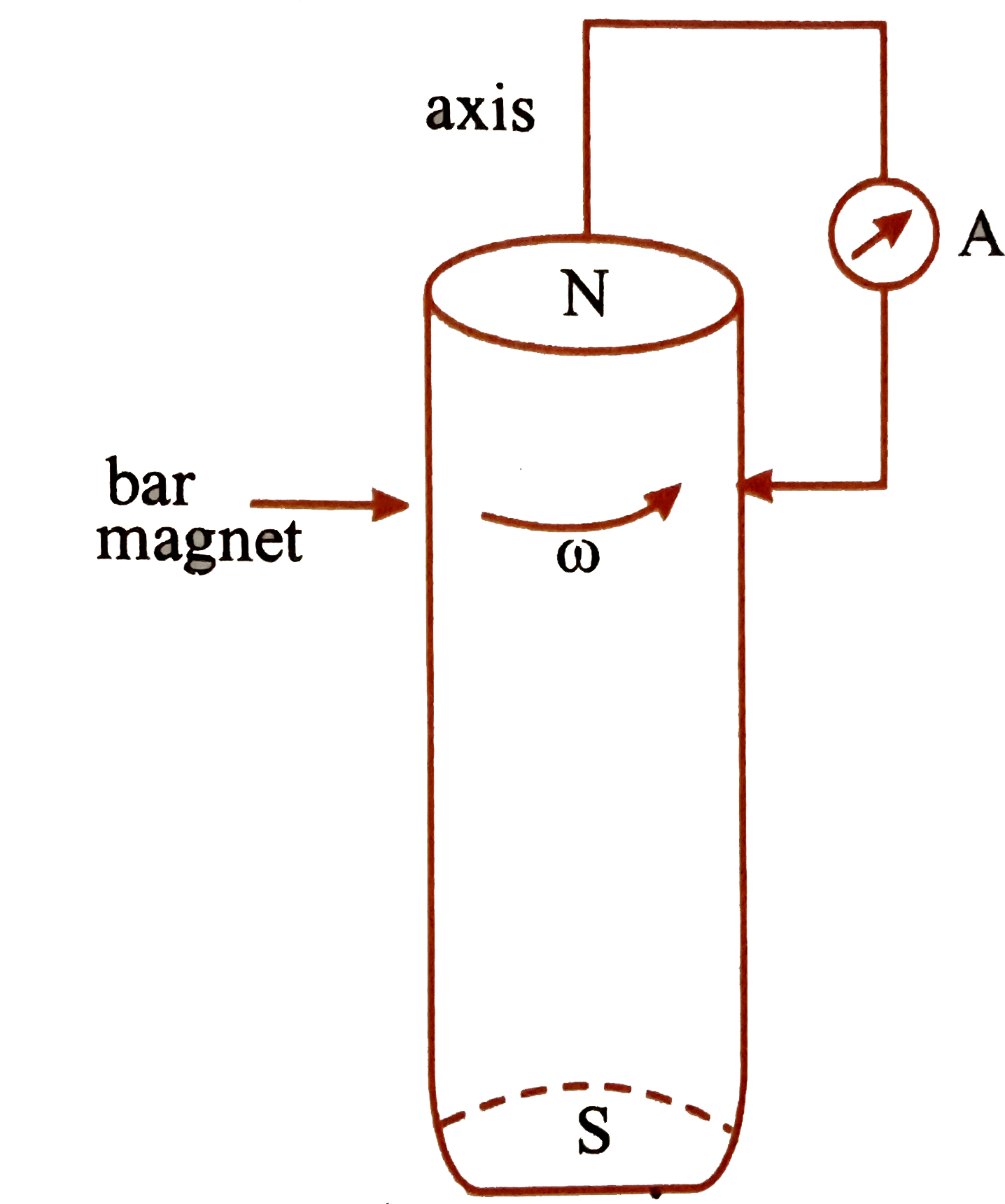
View SolutionA cylindrical bar magnet is rotated about its axis (Figure). A wire is connect from the axis and is made to touch the cylindrical surface through a contact. Then
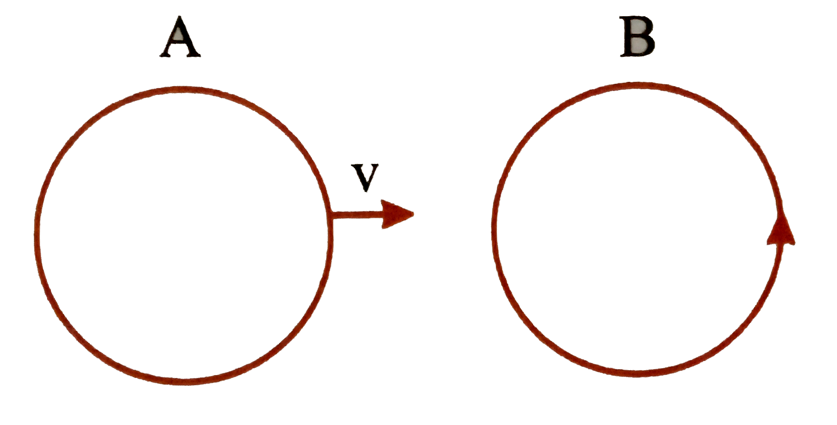
View SolutionThere are two coils `A` and `B` as shown in Figure. A current starts flowing in `B` as shown, when `A` is moved towards `B` and stops when `A` stops moving. The current in `A` is counterclockwise. `B` is kept stationary when `A` moves. We can infer that
View SolutionSame as problem `4` except the coil `A` is made to rotate about a vertical axis in the plane of the coil (Figure). No currents flows in `B` if `A` is at rest. The current in coil `A`, when the current in `B` (at `t = 0`) is counterclockwise and the coil `A` is as shown at this instant, `t = 0`, is
View SolutionA rectangular loop of sides 10 cm and 5 cm with a cut is stationary between the pole pieces of an electromagnet.
The magnetic field of the magnet is normal to the loop. The current feeding the electromagnet is reduced, so that the field decreased from its initial value of 0.2 T at the rate of `0.02Omega`. If the cut is joined and the loop has a resistance of `2.0Omega`, then the power dissipated by the loop as heat is
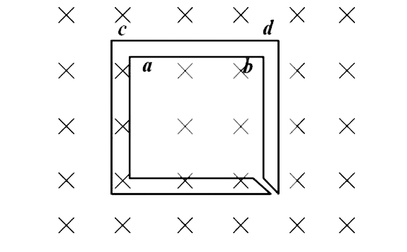
View SolutionThe figure shows certain wire segments joined together to form a coplaner loop. The loop is placed in a perpendicular magnetic field in the direction going into the plane of the figure. The magnitude of the field increases with time `I_(1) and I_(2)` are the currents in the segments ab and cd. Then,
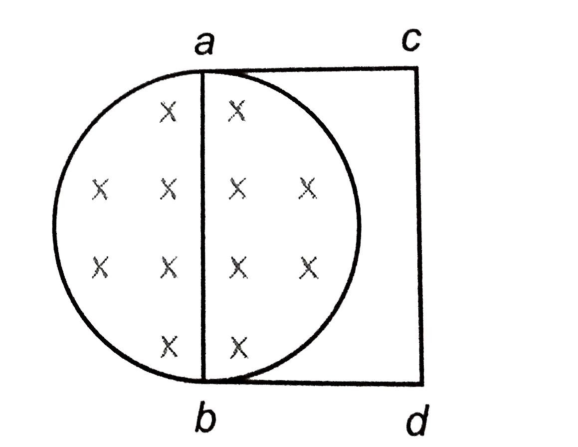
View SolutionA uniform magnetic field `B` exists in a cylindrical region of radius `I0cm` as shown in figure. A uniform wire or length `80cm` and resistance `44.0Omega` is bent into a square frame and is placed with one side along a diameter of the cylindrical region. if the magnetic field increases at a constant rate of `0.0I0T//sec` , the current induced in the frame
View Solutionshows a circular wheel of radius 10.0 cm whose upper half, shown dark in the figure, is made of iron and the lower half of wood. The two junctions are joined by an iron rod. A uniform magnetic field B of magnitude `2.00X 10^(-4) T` exists in the space above the central line as suggested by the figure. The wheel is set into pure rolling on the horizontal surface. The wheel is set into pure rolling on the horizontal surface. If it takes 2.00 seconds for the iron part to come down and the wooden part to go up, find the average emf induced during this period.
(##HCV_VOL2_C38_E01_061_Q01##)
View SolutionA wire of length 10cm translates in a direction making an angle of `60^@` with its length. The plane of motion is perpendicular ot a uniform magnetic field of 1.0 T that exists in the space. Find the emf induced between the ends of the rod if the speed of translation of `20 cm s^(-1)`.
View SolutionThe loop shown moves with a velocity `v` in a uniform magnetic field of magnitude `B`, directed into the paper. The potential differene between point `P` and `Q` is e. Then
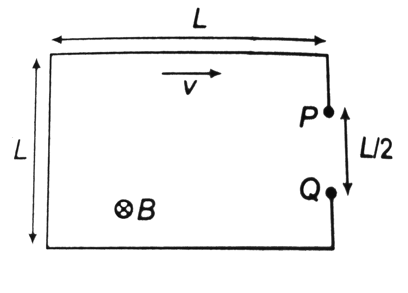
View Solutionshows a conducting loop being pulled out of a magnetic field with a speed v. Which of lthe four plots shown in may represent the power delivered by the pulling agent as a function of the speed v ?
(##HCV_VOL2_C38_E01_022_Q01##)
(##HCV_VOL2_C38_E01_022_Q01##)
View SolutionA square loop of wire with side length 10 cm is placed at angle of `45^(@)` with a magnetic field that changes uniformly from 0.1 T to zero in 0.7s. The induced current in the loop (its resistance is `1Omega`) is
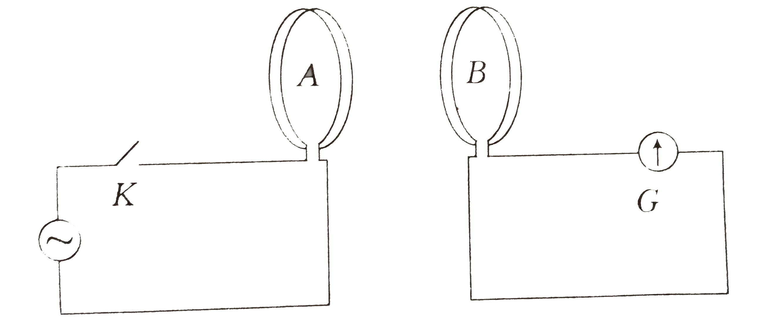
View SolutionThe diagram below shows two coils A and B placed parallel to each other at a very small distance. Coil A is connected to an AC supply. G is a very sensitive galvanometer. When the key is closed
View SolutionA magnet is dropped down an infinitely long vertical copper tube
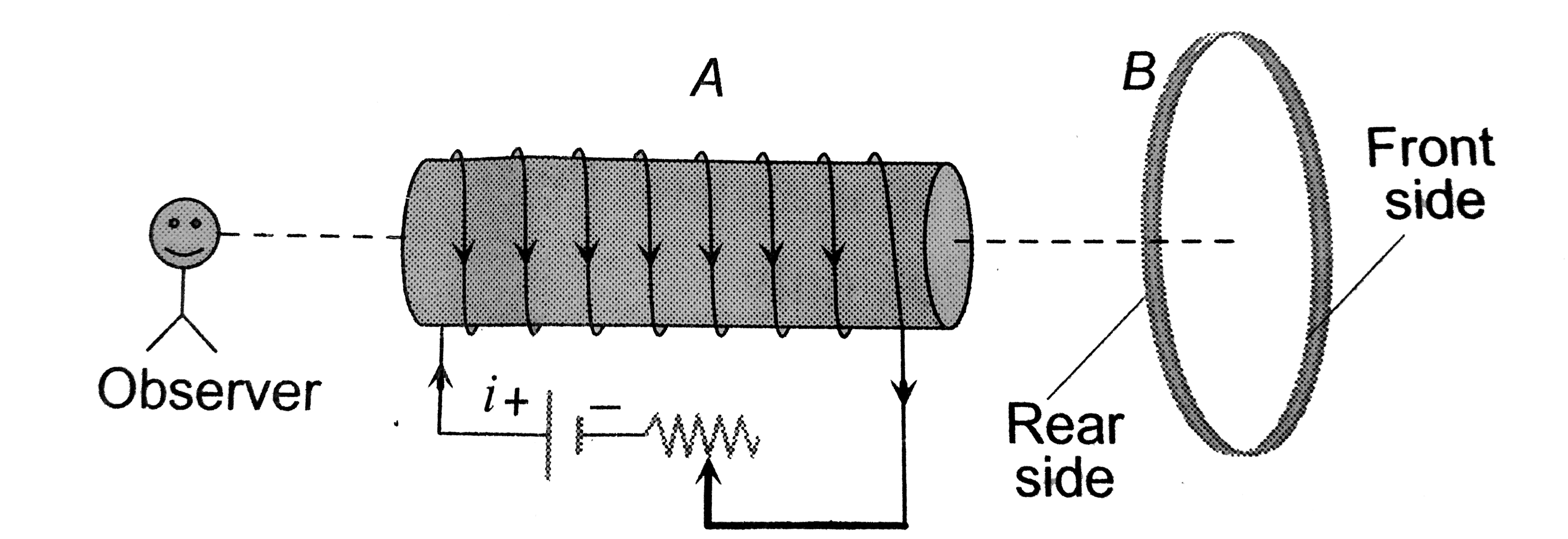
View SolutionAn aluminium ring `B` faces an electromagnet `A`. The current `I` through `A` can be altered
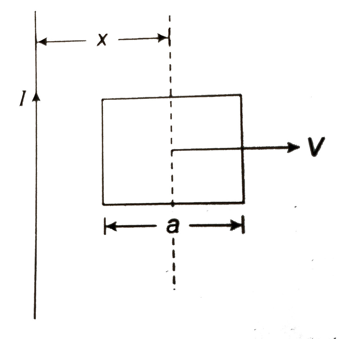
View SolutionA conducting square frame of side `'a'` and a long straight wire carrying current `I` are located in the same plane as shown in the figure. The frame moves to the right with a constant velocity `'V'`. The emf induced in the frame will be proportional to
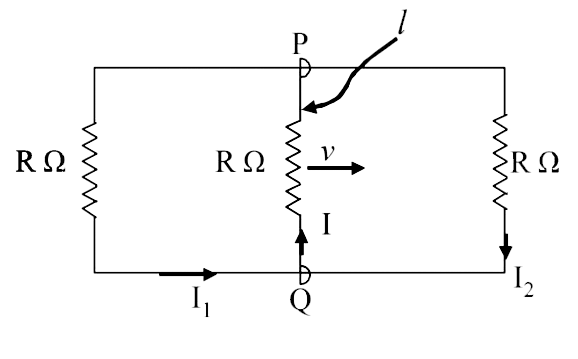
View SolutionA rectangular loop has a sliding connector PQ of length l and resistance `R (Omega)` and it is moving with a speed v as shown. The set-up is placed in a uniform magnetic field going into the plane of the paper. The three currents `I_(1), I_(2)` and I are
View SolutionTwo concentric coils each of radius equal to `2 pi cm` are placed at right angles to each other ` 3 ampere and 4 ampere` are the currents flowing in each coil respectively. The magnetic induction in `weber//m^(2)` at the centre of the coils will be
`( mu_(0) = 4 pi xx 10^(-7) Wb// A.m)`
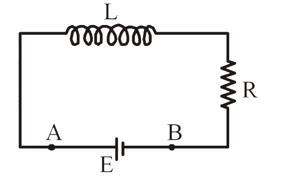
View SolutionAn inductor (L = 100 mH), a resistor `(R = 100Omega)` and a battery (E = 100 V) are initially connected in series as shown in the figure. After a long time the battery is disconnected after short circuiting the points A and B. The current in the circuit 1 ms after the short circuit is
View SolutionThree solenoid coils of same dimension, same number of turns and same number of layers of windings are taken. Coil 1 with inductance `L_(1)` was would using a wire of resistance `11Omega//m`, coil 2 with inductance `L_(2)` was wound using the similar wire but the direction of winding was reversed in each layer, coil 3 with inductance `L_(3)` was wound using a superconducting wire. The self-inductance of the coils `L_(1),L_(2)` and `L_(3)` are
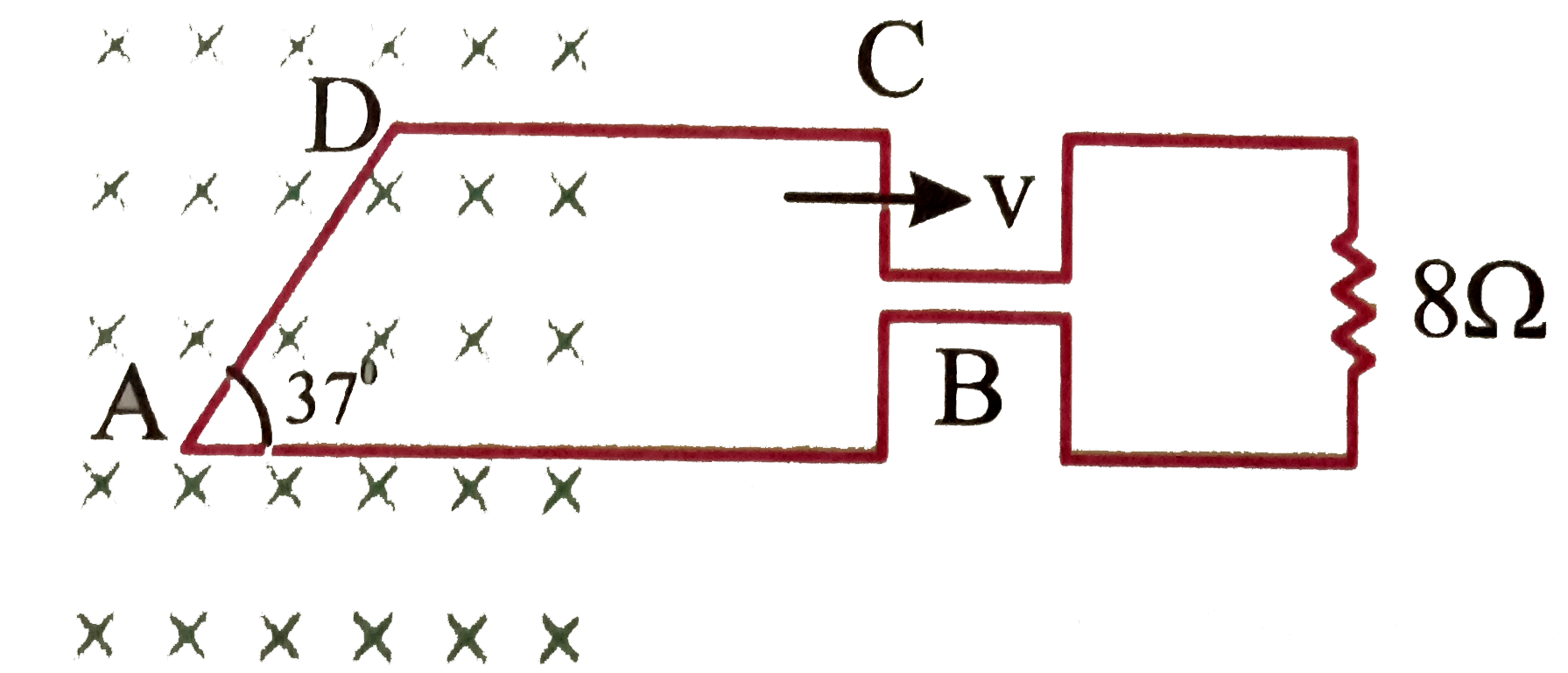
View SolutionThe loop `ABCD` is moving with velocity `'v'` towards right. The magnetic field is `4T`. The loop is connected to a resistance of `8 Omega`. If steady current of `2A` flows in the loop then value of `'v'` if loop has a resistance of `4 Omega`, is : (Given `AB = 30 cm, AD = 30 cm`)
View SolutionA uniform but time varying magnetic field is present in a circular region of radius R. The magnetic field is perpendicular and into the plane of the loop and the magnitude of field is increasing at a constant rate `alpha`. There is a straight conducting rod of length 2R placed as shown in figure.
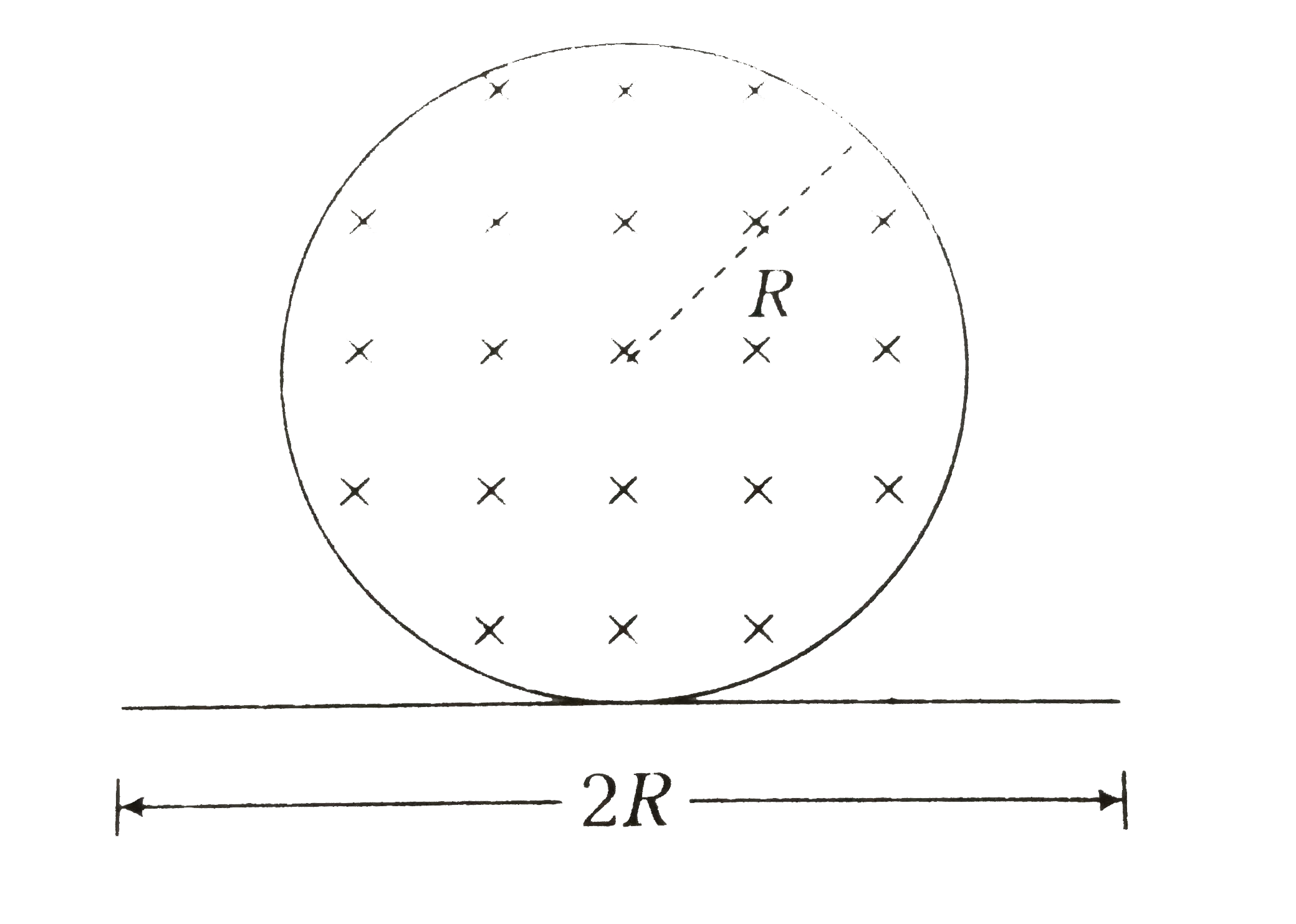
The magnitude of induced emf across the rod is
View Solution
Taking it together questions and complete solutions for chapter ELECTROMAGNETIC INDUCTION of DC PANDEY PHYSICS (HINGLISH) of Class 12
All Exercises from DC PANDEY NEET Class 12 PHYSICS ELECTROMAGNETIC INDUCTION
- Check point
- Example
- Example Type 1
- Example Type 2
- Example Type 3
- Example Type 4
- Example Type 5
- Example Type 6
- Exercise 27.1
- Exercise 27.2
- Exercise 27.3
- Exercise 27.4
- Exercise 27.5
- Exercise 27.6
- Exercise 27.7
- Level 1 Assertion And Reason
- Level 1 Objective
- Level 1 Subjective
- Level 2 Comprehension Based
- Level 2 More Than One Correct
- Level 2 Single Correct
- Level 2 Subjective
- Match the columns
- Medical entrance special format questions
- Medical entrances gallery
- Miscellaneous Examples
- Objective Questions
- SUBJECTIVE TYPE
- Taking it together