Complete Solutions to MULTIPLE CHOICE QUESTIONS ( LEVEL-I) of chapter CURRENT ELECTRICITY of Class 12 book with complete answers and questions
| Class 12 | PHYSICS |
| Chapter | CURRENT ELECTRICITY |
| MODERN PUBLICATION | MULTIPLE CHOICE QUESTIONS ( LEVEL-I) |
| Number Of Questions | 99 |
| Academic Year | 2023-24 |
Two similar cells whether joined in series or in parallel have the same current through an external resistance of `2Omega`, the internal resistance of each cell is :
View SolutionThe external diameter of a 5 m long hollow tube is 10 cm and thickness of its walls is 5 mm. If specific resistance of material is `1.7 xx 10^(-8)Omegam`, then its resistance is :
View SolutionCurrent flows through a metallic conductor whose area of cross-section increases in the direction of current. If we move in this direction :
View SolutionA non-conducting ring of radius R has charge Q. If it rotates with angular velocity co , the equivalent current through it is :
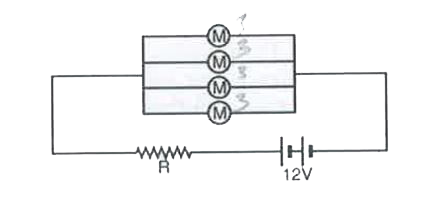
View SolutionFour identical lamps labelled 1·5 V, 0.5 A each which describes the condition necessary for them to operate at normal brightness. A 12 V battery is connected to lamps, find required value of R for lamps to glow with normal brightness :
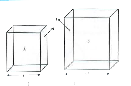
View SolutionTwo square metal plates A and B are of same thickness and material. The side of B is twice that of A. If resistances of A and B are denoted by `R_(A)` and `R_(B)`, then `(R_(A))/(R_(B))` is :
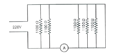
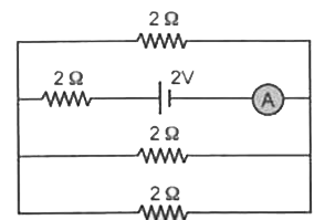
View SolutionThe reading of ammeter is :
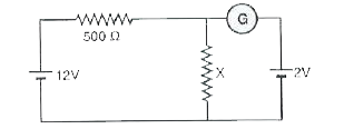
View SolutionIn the circuit given below, galvanometer reads zero, find value of X :
View SolutionFive resistances are connected shown by full lines. Then two additional resistors are connected shown by dotted lines. If `R_(1)` and `R_(2)` are net resistances in two cases then `(R_(2))/(R_(1))` is :
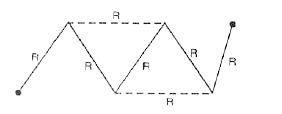
View SolutionIn the circuit, current supplied by battery is :
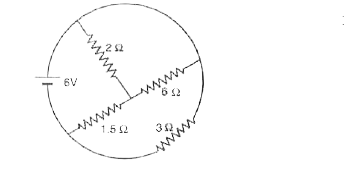
View SolutionTwo metallic wires whose masses are 12 g and 18 g have lengths in the ratio of 3 : 4. Their resistances are in the ratio of :
View SolutionIn the circuit shown, the internal resistances are `r_(1)` and `T_(2)` . The external resistance is 8 ohm. If the voltmeter put across the first cell, gives no deflection, then:
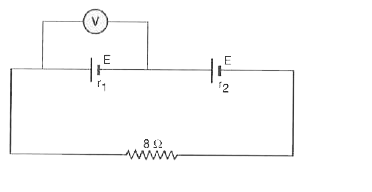
View Solution81 cells each of e.m.f. 2 V and internal resistance 1-5 ohm are connected to supply a maximum current through an external resistance of `9 xx 10^(-3)` ohm. Then the cells must be connected in :
View SolutionA conductor of resistance `3Omega` is stretched uniformly till its length is doubled. The wire is now bent in the form of an equilateral triangle. The effective resistance between ends of any side of triangle in ohm is :
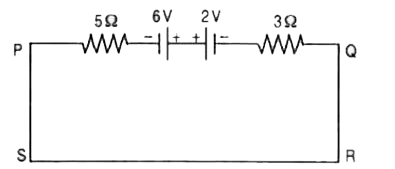
View SolutionWhat is the potential difference between P and Q in the circuit shown here ?
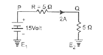
View SolutionA copper wire of length L and radius r is nickel plated till final radius is R. If the specific resistance of copper and nickel by `p_(c)` and `p_(n)`, then the conductance of wire will be:
View SolutionTwo electric bulbs marked 500 W, 220 V are put in series with 110 V line. The power dissipated in each of the bulb is :
View SolutionTwo resistances `R_(1)` and `R_(2)` when connected in series consume power equal to 25 W. When connected in parallel they consume 100 W. What is the ratio of power of each ?
View SolutionThere is a frill of 40 bulbs connected in series. One bulb gets fused. The remaining 39 bulbs are joined in series and connected to same supply. Will the illumination decrease or increase in the room ?
View SolutionTwo bulbs rated 25 W-220 V and 100 W-220 V are connected in series to a 440 V supply. Show that:
View SolutionIf in above question, hoth bulbs are connected in parallel, then :
View SolutionAll bulbs below are identical, which bulb(s) light(s) most brightly ?
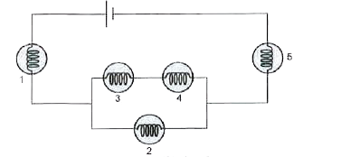
View SolutionThe drift velocity of the electron in a conductor is `v_(d)=J/(ne)` where J = current density.
Therefore, the drift velocity is :
View Solution
Given AB is thicker wire of length 1 m. CD has the same length and of the same material but is thinner.
Choose the right statements :
View Solution
`R_(1)ltR_(2)` length is the same for AB and CD as in question 24. Choose the correct statements :
View SolutionCross-section area of `CD=1/2` cross-section area of AB. Choose the correct statements

View SolutionStatement-1 : In series combination of resistors, p.d. is divided among them, in the direct ratio of the resistances.
Stament-2 In parallel combination of resistors, currents are divided in direct ratio of the resistances,
View SolutionStatement-1 : If 25 W and 100 W bulbs are joined in series and connected to mains, then 25 W bulb will glow brighter.
Statement-2 : 100 W bulb draws more current from mains.
View SolutionWheatstone's bridge is a very simple but powerfull concept which has made many calculations easy. If the assumption is made that current does not flow through the galvanometer from B to C or C to B,
`V_(A)-V_(B)=V_(A)-V_(D)` `V_(B)-V_(D)=V_(C)-V_(D)`
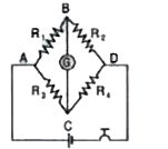
The current in R1, has to flow through BD and that in `R_(3)` through CD. This idea has been extended to many symmetrical circuits.
For Wheatstone's bridge,
View SolutionWheatstone's bridge is a very simple but powerfull concept which has made many calculations easy. If the assumption is made that current does not flow through the galvanometer from B to C or C to B,
`V_(A)-V_(B)=V_(A)-V_(D)` `V_(B)-V_(D)=V_(C)-V_(D)`
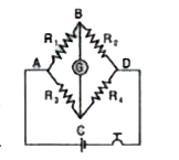
The current in R1, has to flow through BD and that in `R_(3)` through CD. This idea has been extended to many symmetrical circuits.
If `R_(1) = 2` ohm, `R_(3) = 4` ohm,`R_(2)= 5` ohm, `R_(4) = 10` ohm and `i_(R_(1)) = 1A`, then the current in `R_(3)` is:
View SolutionWheatstone's bridge is a very simple but powerfull concept which has made many calculations easy. If the assumption is made that current does not flow through the galvanometer from B to C or C to B,
`V_(A)-V_(B)=V_(A)-V_(D)` `V_(B)-V_(D)=V_(C)-V_(D)`
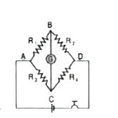
The current in R1, has to flow through BD and that in `R_(3)` through CD. This idea has been extended to many symmetrical circuits.
If the position of the galvanometer is exchanged with that of the battery in the Wheatstone's bridge shown in the passage.
View SolutionThe idea of the bridge has been extrapolated to complicated symmetric circuits. If all these resistances are equal, then `(R_(AB))/(R_(AC))=1=(R_(BD))/(R_(CD))`.
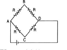
This is a Wheatstone's bridge.
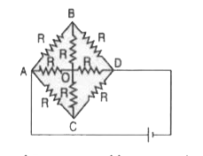
If now A and D connected by two resistances R and R and B also connected to O and O to C as shown above.
The current in BO is :
View SolutionThe idea of the bridge has been extrapolated to complicated symmetric circuits. If all these resistances are equal, then `(R_(AB))/(R_(AC))=1=(R_(BD))/(R_(CD))`.
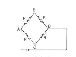
This is a Wheatstone's bridge.
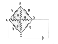
If now A and D connected by two resistances R and R and B also connected to O and O to C as shown above.
The total resistance is :
View SolutionResistance of a wire at 20°C is `20Omega` and at 500°C is `60Omega`. At what temperature its resistance is `25Omega`.
View SolutionThe temperature coefficient of resistance for a wire is 0.00125/°C. At 300K its resistance is 1 ohm. The temperature at which the resistance becomes 2 ohm is :
View SolutionThe resistance of a wire is 20 ohm. It is so stretched that the length becomes three times, then the new resistance of the wire will be :
View SolutionWhen a piece of aluminium wire of finite length is drawn through a series of dies to reduce its diameter to half its original value, its resistance will become.
View SolutionConsider a rectangular slab of length L and area of cross section A. A current I is passed through it. If the length is doubled, the potential drop across the end faces
View SolutionThe resistance of a metal increases with increasing temperature because
View SolutionIn the absence of applied potential, the electric current flowing through a metallic wire is zero because
View SolutionA metal were is subjected to a constant potential difference. When the temperature of the metal wire increases, the drift velocity of the electron in it
View SolutionTwo resistances of `10Omega` and `20Omega` and an inductor of inductance 5H are connected to a battery of 2V through a key k as shown in the figure.
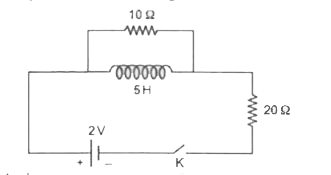
At time t = 0, when the key k is closed the initial current through the battery is
View SolutionTwo different conductors have same resistance at 0°C. It is found that the resistance of the first conductor at `t_(1)` °C is equal to the resistance of the second conductor at `t_(2)` °C. The ratio of the temperature coefficients of resistance of the conductors `alpha_(1)//a_(2)` is:
View SolutionThe resistance of a wire at room temperature 30° C is found to be 100. Now to increase the resistance by `10Omega`, the temperature of the wire must be [The temperature coefficient of resistance of the material of the wire is 0.002 per `""^(@)C`]
View SolutionMasses of three wires of copper are in the ratio of 1 : 3 : 5 and their lengths are in the ratio of 5 : 3 : 1. The ratio of their electrical resistances are
View SolutionAt room temperature, copper has free electron density of `8.4 xx 10^(28)` per `m^(3)`. The copper conductor has a crosssection of `10^(-6) m^(2)` and carries a current of 5.4 A. The electron drift velocity in copper is :
View SolutionExpress which of the following setups can be used to verify Ohm's law ?
View SolutionThe graph between resistivity and temperature, for a limited range of temperature, is a straight line for a material like
View SolutionThe tolerance level of a resistor with the ,colour code red, blue, orange, gold is :
View SolutionIn a conductor if 3000 coulomb of charge enters and 3000 coulomb of charge exits in time 10 minutes, then the current is :
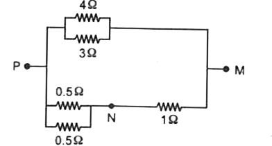
View SolutionIn the circuit shown, the current through the 4Q resistor is 1 A when the points P and M are connected to a d.c. voltage source. The potential difference between the points M and N is :
View SolutionThe reading of the ammeter as per figure shown is :
View SolutionNine resistors each of 1 `kOmega` are connected to a battery of 6V as shown in the circuit given below.
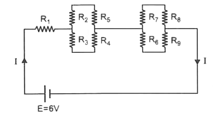
What is the total current flowing in the circuit ?
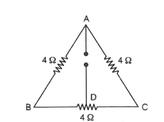
View SolutionThree resistances of `4Omega` each are connected as shown in figure. If the point D divides the resistance into two equal halves, the resistance between point A and D will be:
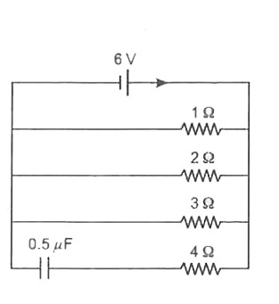
View SolutionThe potential difference between A and B in the following figure is :

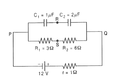
View SolutionIn the given circuit diagram the current through the battery and the charge on the capacitor respectively in steady state are
View SolutionA metallic wire of resistance of `12Omega` is bent to form a square. The resistance between two diagonal points would be :
View SolutionFigure shows a network of eight resistors, each equal to `2Omega`, connected to a 3V battery of negligible internal resistance.
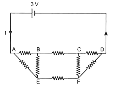
The current I in the circuit is :
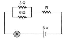
View SolutionIf the ammeter in the given circuit reads 2 A, the resistance R is :
View SolutionResistors of 1, 2, 3 ohm are connected in the form of a triangle. If a 1.5 volt cell of negligible internal resistance is connected across 3 ohm resistor, the current flowing through this resistance will be :
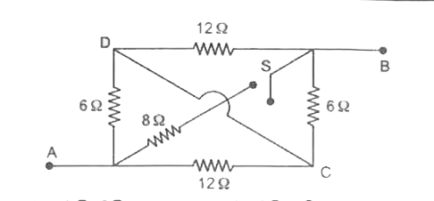
View SolutionThe equivalent resistance between points A and B with switch S open and closed are respectively.
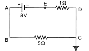
View SolutionIn the given circuit, the potential of the point E is :
View SolutionIn the Wheatstone's network given, `P = 10 Omega, Q = 20Omega, R = 15Omega, S = 30Omega`. The current passing through the battery ( of negligible internal resistance) is :
View SolutionThe internal resistances of given cells are negligible in given circuit. The current in given circuit is :
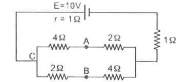
View SolutionIn the circuit shown below, the cell has an e.m.f. of 10V and internal resistance of 1 ohm. The other resistances are shown in the figure. The potential difference `V_(A) - V_(B)` is :
View SolutionThree resistances of values `2Omega, 3Omega`, and `6Omega` are to connected to produce an effective resistance of `4Omega`. This can be done by connecting
View SolutionTwo wires of equal diameters, of resistivities `p_(1)` and `p_(2)` and lengths `l_(1)` and `l_(2)`, respectively, are joined in series. The equivalent resistivity of the combination is :
View SolutionAn unknown resistance `R_(1)` is connected in series with a resistance of `10Omega`. This combinations is connected to one gap of a metre bridge while a resistance `R_(2)` is connected in the other gap. The balance point is at 50 cm. Now, when the `10Omega` resistance is removed the balance point shifts to 40 cm. The value of `R_(1)` is : (in ohm)
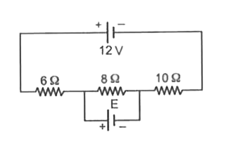
View SolutionIn the circuit shown, the current through 8 ohm is same before and after connecting E. The value of E is :
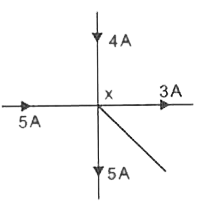
View SolutionFive conductors are meeting at a point x as shown in the figure. What is the value of current in fifth conductor ?
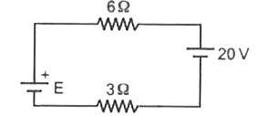
View SolutionCalculate the value of E, for given circuit, when value of 2 A current is either flowing in clockwise or anticlockwise direction
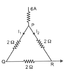
View SolutionA current of 6A enters one corner P of an equilateral triangle PQR having 3 wires of resistances `2Omega` each and leaves by the comer R. Then the current `I_(1)` and `I_(2)` are :
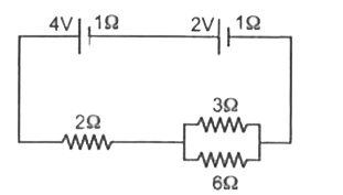
View SolutionTwo cells having e.m.f. 4V, 2V and internal resistances `1Omega, 1Omega` are connected as shown in figure. Current through `6Omega` resistance is :
View SolutionA battery of e.m.f E has an internal resistance 'r'. A variable resistance R is connected to the terminals of the battery. A current I is drawn from the battery. V is the terminal P.O. If R alone is gradually reduced to zero, which of the following best describes I and V
View SolutionA cell in secondary circuit gives null deflection for 2.5m length of potentiometer having 10m length of wire. If the length of the potentiometer wire is increased by 1 m without changing the cell in the primary, the position of the null point now is :
View SolutionA wire when connected to 220 V mains supply has power dissipation `P_(1)`. Now the wire is cut into two equal pieces which are connected in parallel to the same supply. Power dissipation in this case is `P_(2)`. Then `P_(2) : P_(1)` is:
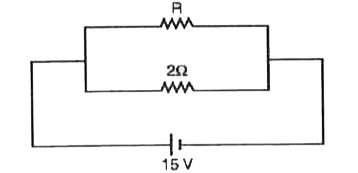
View SolutionIf in the circuit, power dissipation is 150 W, then R is :
View SolutionA 220 V, 1 000W bulb is connected across a 110 V mains supply. The power consumed is :
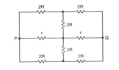
View SolutionThe effective resistance between points P and Q of the electrical circuit shown in fig. is :
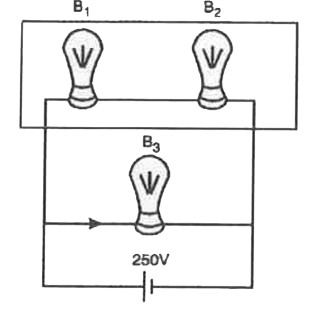
View SolutionA 100 W bulb `B_(1)`, and two 60 W bulbs `B_(2)` and `B_(3)`, are connected to a 250 V source, as shown in Fig. Now `W_(1), W_(2)` and `W_(3)` are the output powers of the bulbs `B_(1), B_(2)` and `B_(3)`, respectively. Then :
View SolutionAn ammeter reads upto 1 ampere. Its internal resistance is 0.81 ohm. To increase the range to 10 A the value of the required shunt is :
View SolutionThe length of a wire of potentiometer is 100 cm, and the e.m.f. of its standard cell is E volt. It is employed to measure the e.m.f. of a battery whose internal resistance is 0.5 `Omega`. If the balance point is obtained at l = 30 cm from the positive end, the e.m.f. of the battery is:
View SolutionN identical light bulbs, each designed to draw P power from a certain voltage supply, are joined in series across that supply. Toe total power which they will draw is :
View SolutionThree resistances of equal value are connected in four different combinations as shown in the figure. Arrangement them in increasing order of power dissipation :

View SolutionWhich of the circuits shown in the figure can be used to verify Ohm's law ?
View SolutionThe total current supplied to the circuit by the battery is
View SolutionThe resistance of the series combination of two resistance is S. When they are joined in parallel the total resistance is P. If S = nP, then the minimum possible value of n is :
View SolutionAn electric current is passed through a circuit containing two wires of the same material, connected in parallel. If the lengths and radii of the wires are in the ratio of 4/3 and 2/3, then the ratio of the currents passing through the wire will be :
View SolutionWhen a 100W electric bulb and a 100 W heater operate at their rated voltages, the filament of the bulb reaches a much higher temperature than the filament of the heater because :
View SolutionA 100-W bulb and a 25-W bulb are designed for the same voltage. They have filaments of the same length and material. The ratio of the diameter of the 100-W bulb to that of the 25-W bulb is :
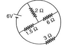
View SolutionWhat is P.D. between points in given circuit?
View SolutionIn given circuit shown in fig. ammeter A reads zero, if batteries have negligible internal resistance, value of R is:

View SolutionA moving coil galvanometer has 150 equal divisions. Its current sensitivity is 100 divisions per milliampere and voltage sensitivity is 2 divisions per millivolt. In order that each division reads 1 volt, the resistance in ohm needed to be connected in series with the coil be
View SolutionTwo sources of equal e.m.f are connected to an external resistance R. The internal resistances of the two sources are `R_(1)` and `R_(2) (R_(2) gt R_(1))`. If the potential difference across the source having internal resistance Rz is zero, then:
View SolutionAn energy source will supply a constant current into the load if its internal resistance is :
View SolutionIn a potentiometer experiment the balancing with a cell is at length 240 cm. On shunting the cell with a resistance of `2Omega`, the balancing length becomes 120 cm. The internal resistance of the cell is
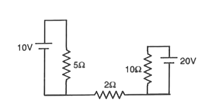
View SolutionFind the current through `2Omega` :
View SolutionThe resistance of a wire is 5 ohm at 50°C and 6 ohm at 100°C. The resistance of the wire at 0°C will be :
View SolutionTo verify Ohm's law, a student is provided with a test resistor `R_(T)` , a high resistance `R_(1)`, a small resistance `R_(2)`, two identical galvanometers `G_(1)` and `G_(2)`, and a variable voltage source V. The correct circuit to carry out the experiment is :
View Solution
MULTIPLE CHOICE QUESTIONS ( LEVEL-I) questions and complete solutions for chapter CURRENT ELECTRICITY of MODERN PUBLICATION PHYSICS (KANNADA ENGLISH) of Class 12