Complete Solutions to WB JEE WORKOUT (CATEGORY 3 : Single Option Correct Type) of chapter SOLID STATE ELECTRONS of Class 12 book with complete answers and questions
| Class 12 | PHYSICS |
| Chapter | SOLID STATE ELECTRONS |
| MTG-WBJEE | WB JEE WORKOUT (CATEGORY 3 : Single Option Correct Type) |
| Number Of Questions | 15 |
| Academic Year | 2023-24 |
In a p- n junction diode not connected to any circuit,
03:07View SolutionIn the following circuit, the output `Y` for all possible inputs `A` and `B` is expressed by the truth table:
 01:58View Solution
In Fig. `V_(0)` is the potential barrier across a `p-n` junction, when no battery is connected across the junction :
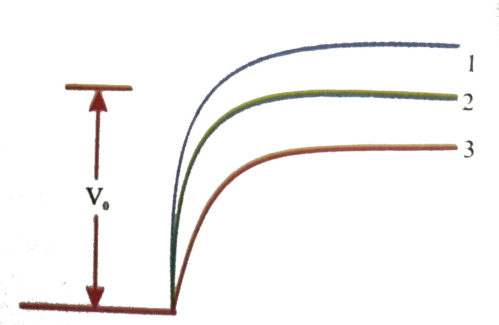 .03:05View Solution
In figure , assuming the diodes to be ideal ,
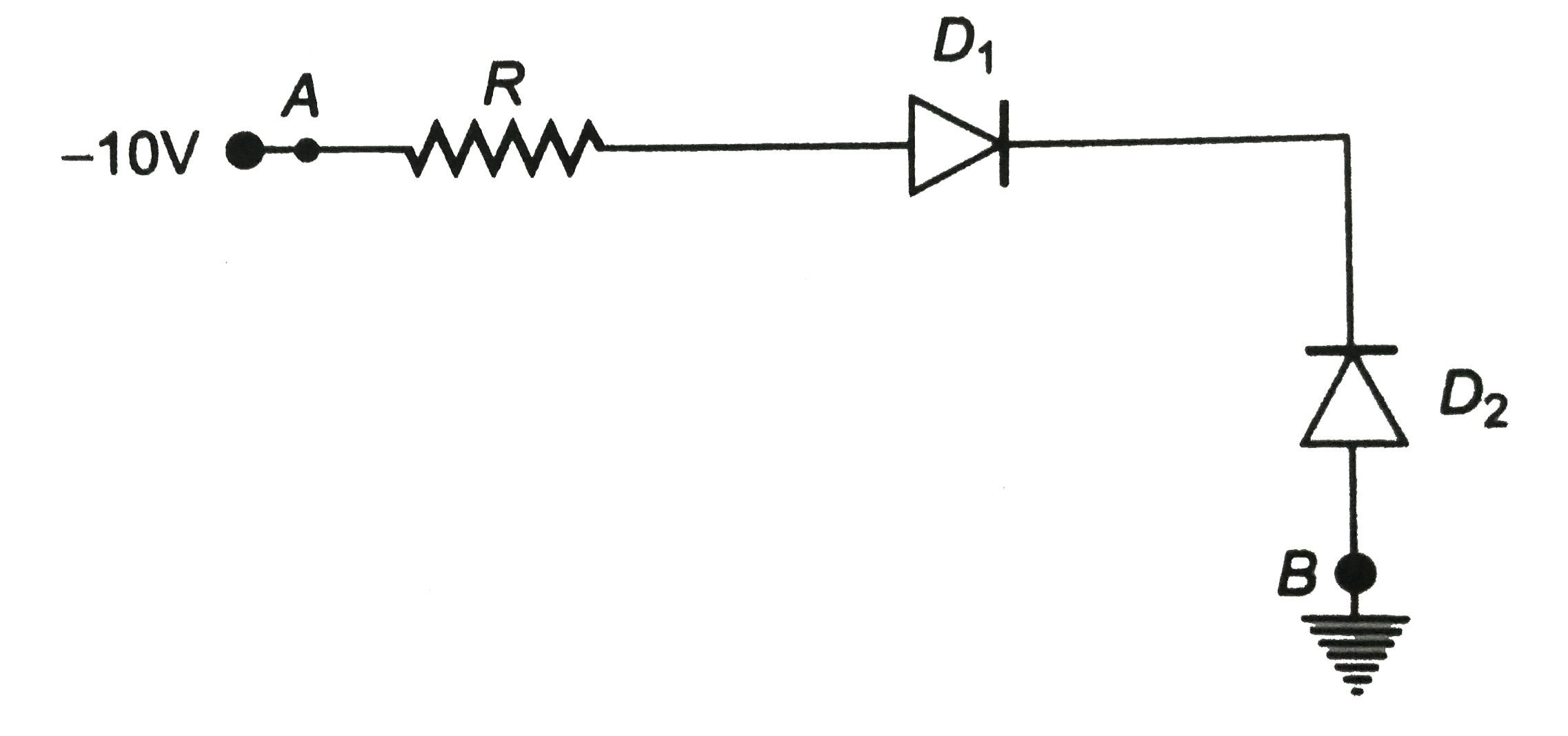 02:08View Solution
Truth table for the given circuit is
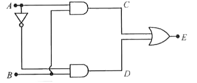 02:09View Solution
In the circuit shown(Fig.) if the diode forward voltage drop is `0.3 V`, the voltage difference between `A` and `B` is :
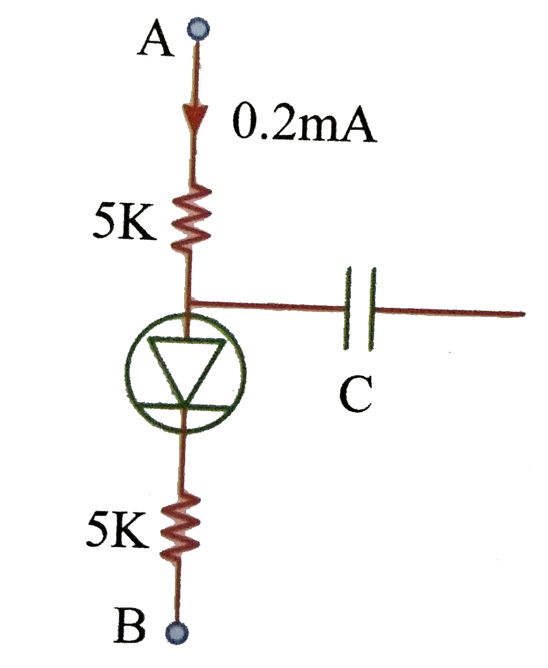 .02:45View Solution
The real time variation of input signals A and B are as shown below. If the inputs are fed into NAND gate, then select the output signal from the following :-
_E01_434_Q01.png) 02:18View Solution
02:18View SolutionThe logic circuit shown below has the input waveforms 'A' and 'B' as shown. Pick out the correct output waveform
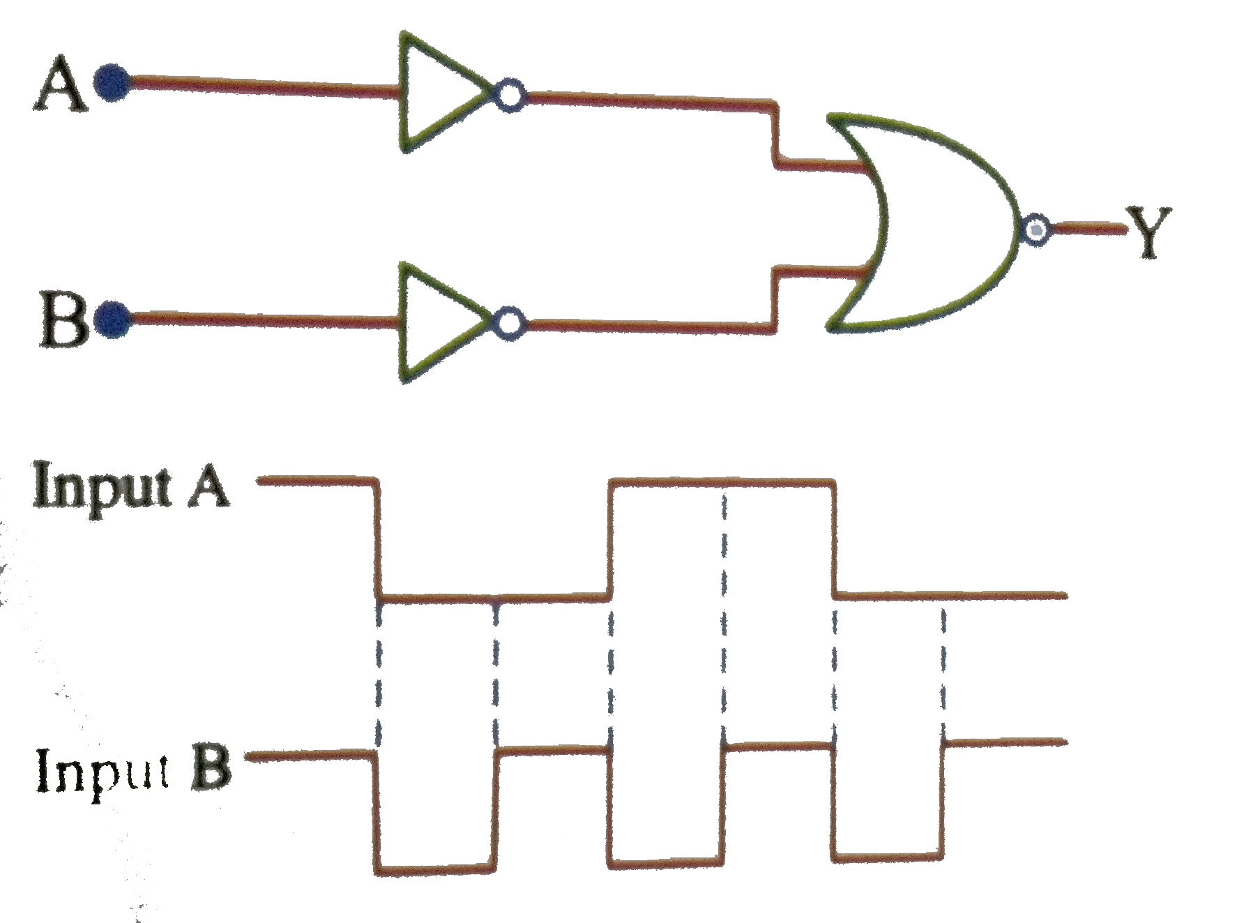 .03:28View Solution
If `beta, R_(L)` and r are the AC current gain, load resistance and the input resistance of a transistor respectively in CE configuration, the voltage and the power gains respectively are
02:03View SolutionIn a semiconductor material `(1//5)`th of the total current is carried by the holes and the remaining is carried by the electrons. The drift speed of electrons is twice that of holes at this temperature. Thr ratio between the number densities of electrons and holes is
04:59View SolutionAn n-p-n transistor can be considered to be equivalent to two diodes, connected. Which of the following figures is the correct one ?
03:32View SolutionIn the given circuit the current through the zener diode is
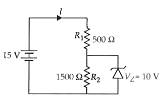 06:31View Solution
The graph shown in Fig. represents the I-V characteristics of a zener diode. Which part of the characteristics curve is most relevent for its operation as a voltage regular?
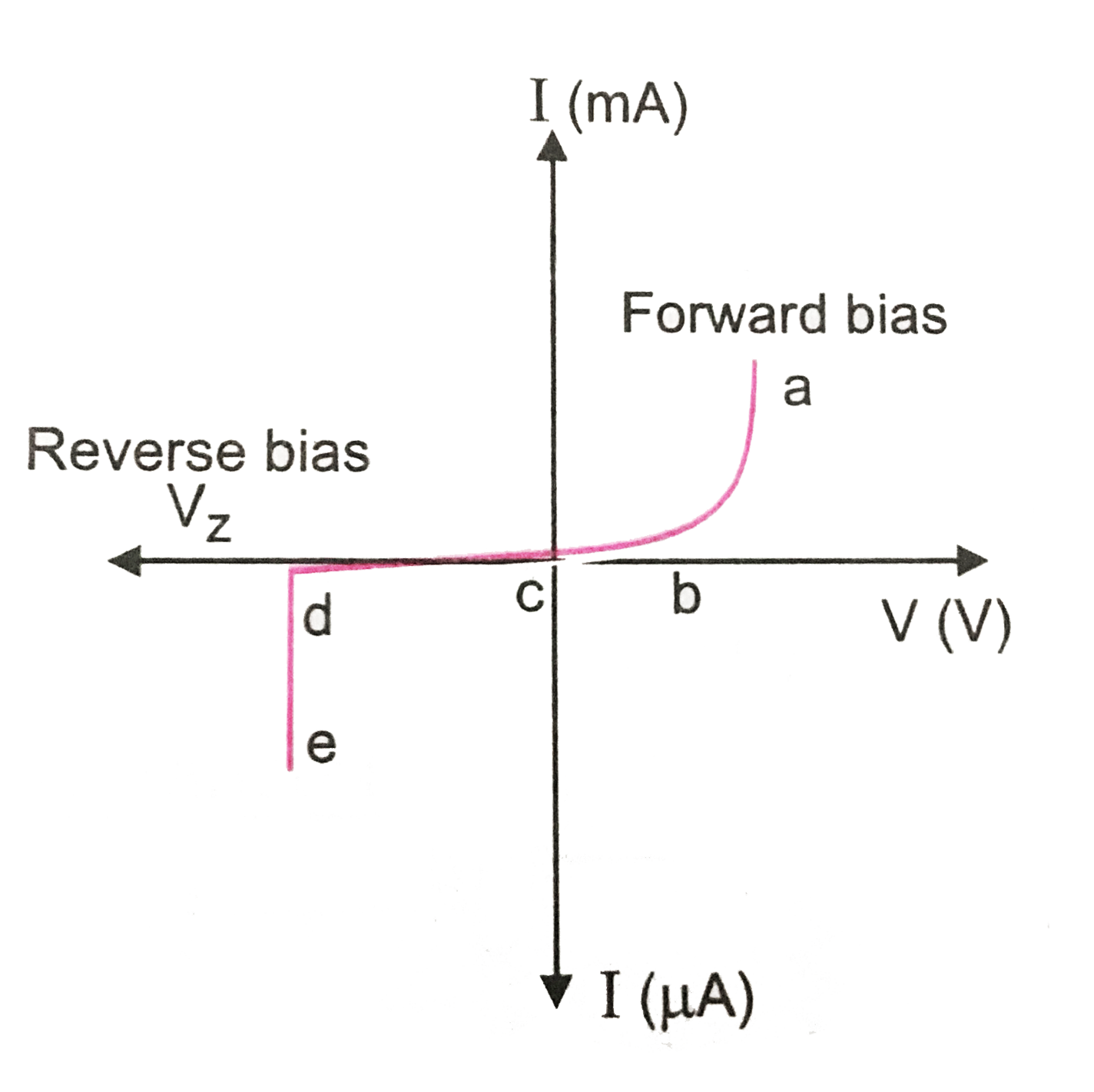 05:21View Solution
The diode used in the circuit shown in the figure has a constant voltage drop of `0.5 V` at all currents and a maximum power rating fo `100` milliwatts. What should be the value of the resistor `R`, connected in series with the diode for obtaining maximum current?
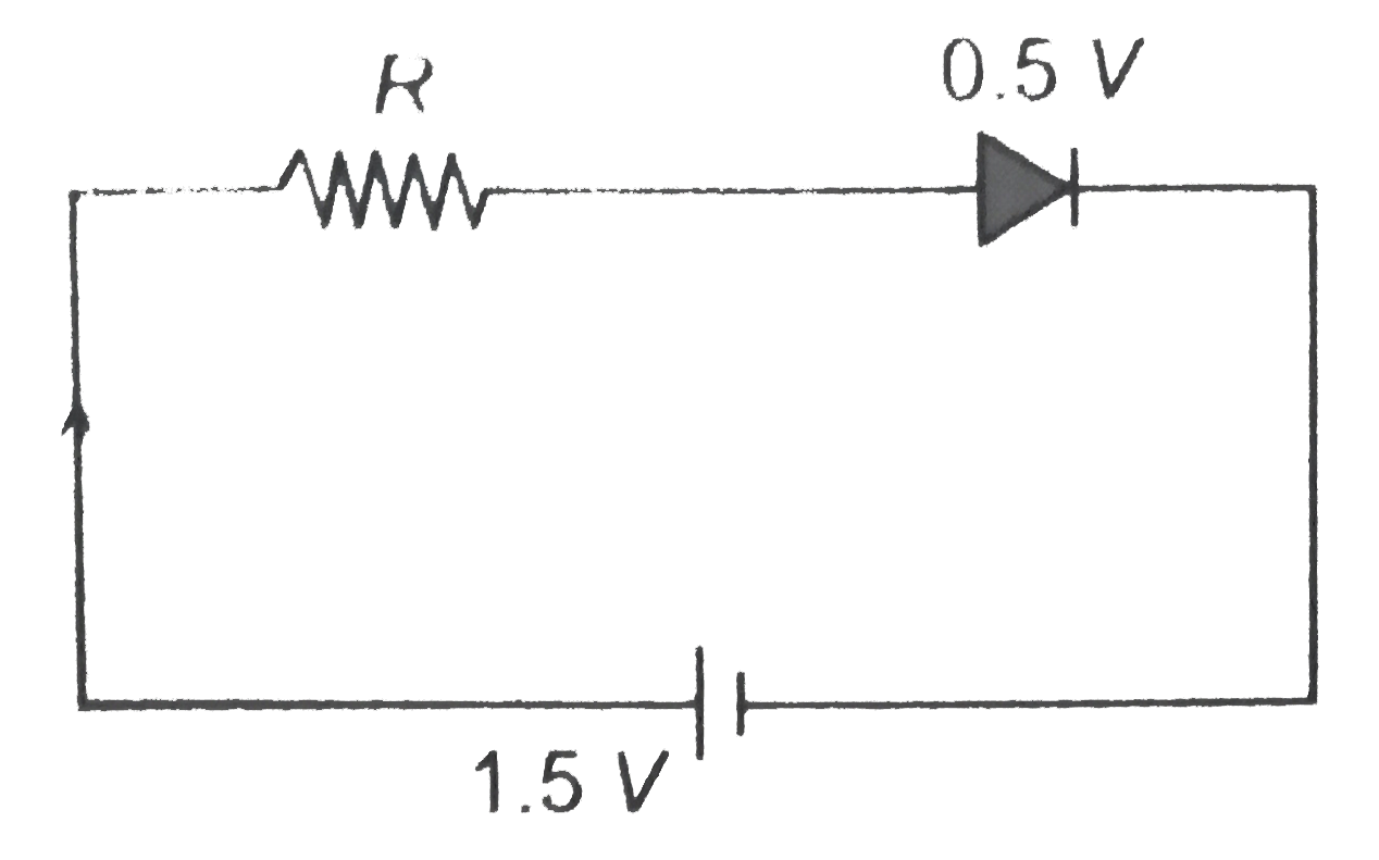 03:16View Solution
Truth table for system of four NAND gates as shown is
 03:18View Solution
WB JEE WORKOUT (CATEGORY 3 : Single Option Correct Type) questions and complete solutions for chapter SOLID STATE ELECTRONS of MTG-WBJEE PHYSICS (HINGLISH) of Class 12
