Complete Solutions to Illustrative Example of chapter ELECTROMAGNETIC INDUCTION AND ALTERNATING CURRENT of Class 12 book with complete answers and questions
| Class 12 | PHYSICS |
| Chapter | ELECTROMAGNETIC INDUCTION AND ALTERNATING CURRENT |
| PHYSICS GALAXY | Illustrative Example |
| Number Of Questions | 50 |
| Academic Year | 2023-24 |
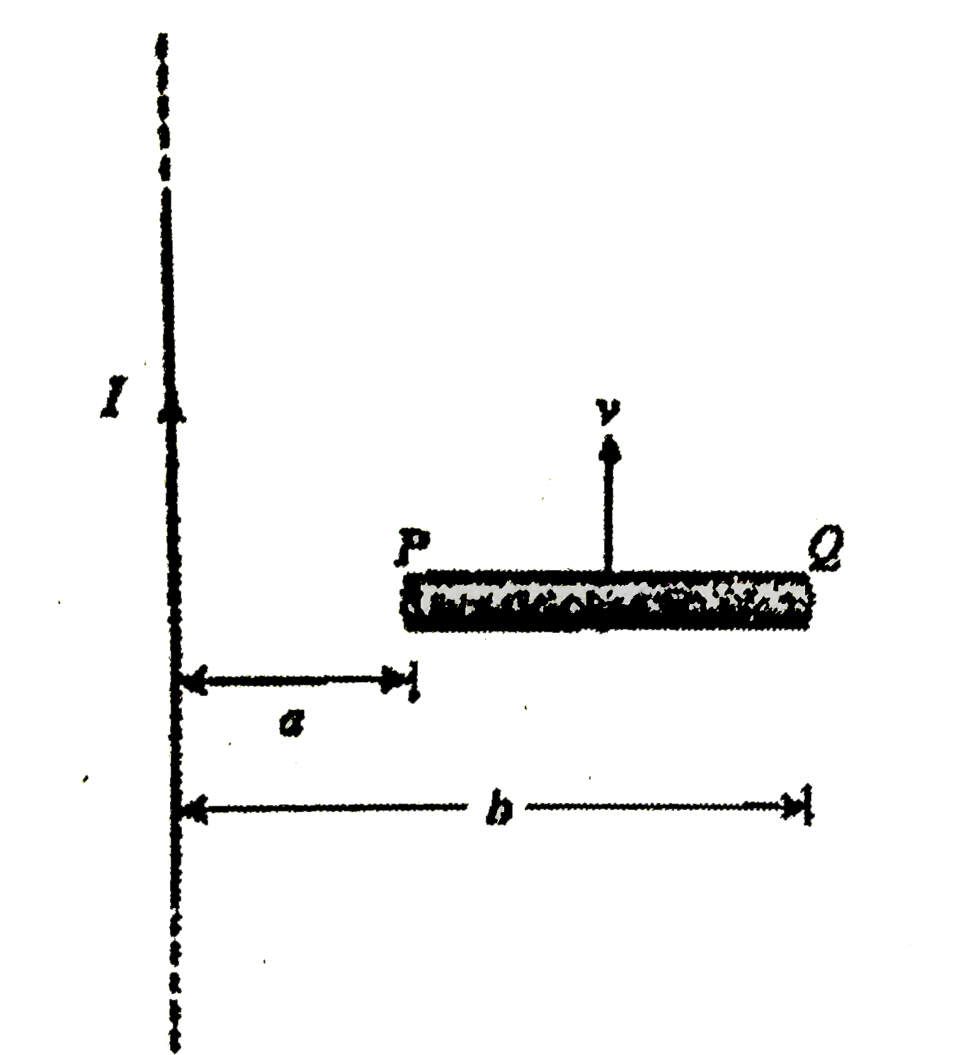
A copper rod of length L is moving at a uniform speed v parallel to along straight wire carrying a current of I as shown in figure-5.25. The rod is perpendicular to the wire with its ends at distance a and b from if . Calculate the motional EMF induced in the rod.
View SolutionA circular cpper disc of 10 cm in diameter rotates at 1800 revolution per minute about an axis through its centre and at right angles to disc. A uniform field of induction B of `1Wb^(-2)m` is perpendicular to disc. What potential difference is developed between the axis of the disc and the rim?
View SolutionA copper connector of mass `m` slides down two smooth cooper bars, set at an angle `alpha` to the horizontal due to gravity (Fig). At the top the bars is equal to `l`. The system is located in a unifrom magnetic field of induction `B`, perpendicular to the plane in which the connector slides. The resistances of the bars, the connector and the sliding contacts, as well as the self-inductance of the loop, are assumed to be negligible. Find the steady-state velocity of the connector.

View SolutionA straight horizontal conductor PQ of length l, and mass_ m slides down on two smooth conducting fixed parallel rails, set inclined at an angle 9 to the horizontal as shown in figure-5.30.
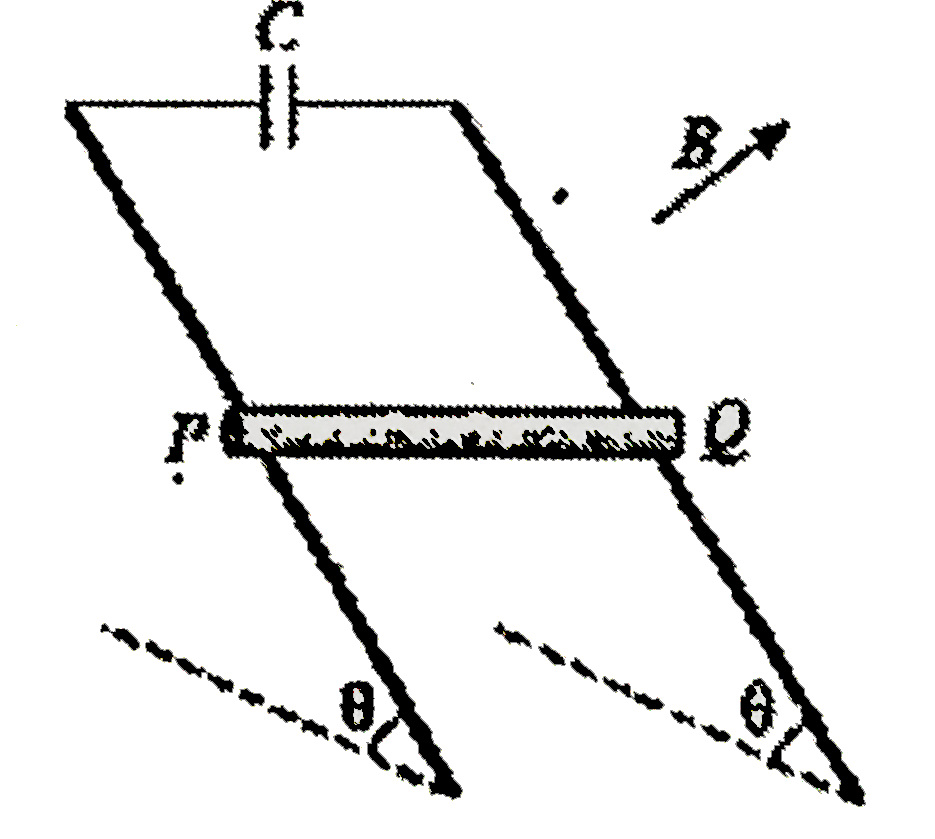 The top end of the bar are connected with a capacitor of capacitance C. The system is placed in a uniform magnetic field, in the direction perpendicular to the inclined plane formed by the rails as shown in figure. If the resistance of the bars and the sliding conductor are negligible calculate the acceleration of sliding conductor as a function of time ifit is released from rest at t= 0
View SolutionA magnetic field `B = B_(0) (y//a)(hat)k` is into the paper in the +z direction, `B_(0)` and a are positive constants. A square loop EFGH of side a, mass m and resistance R, in x-y plane, starts falling under the influence of gravity see figure. Note the direction of x and y axis in figure.
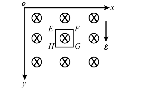
Find
(a) the induced current in the loop and indicate its direction.
(b) the total Lorentz force acting on the loop and indicate its direction, and
(c) an expression for the speed of the loop, v(t) and its terminal value.
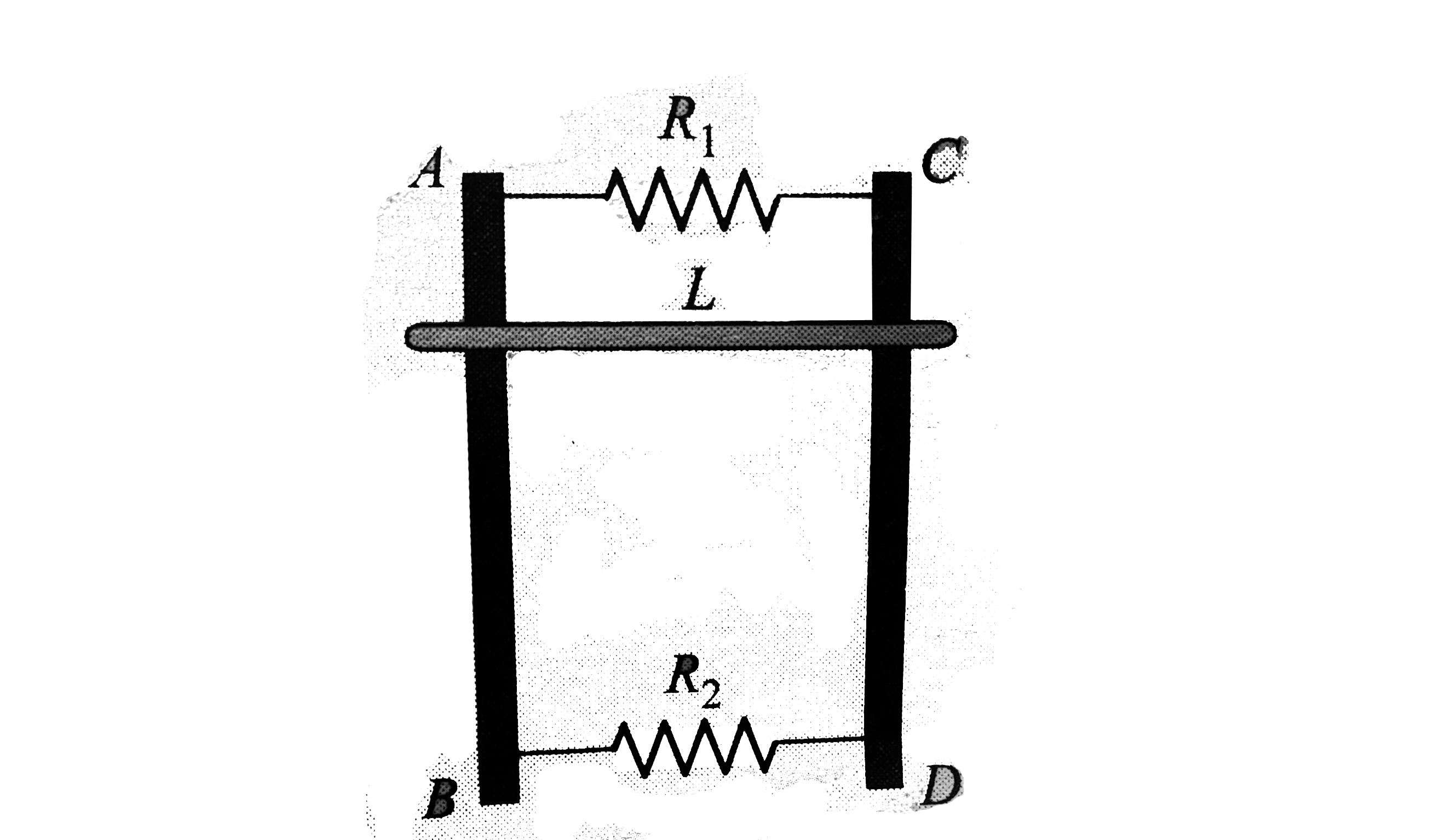
View SolutionTwo parallel vertical metellic rails `AB` and `CD` are separated by `1m`. They are connecting at two ends by resistances `R_(1)` and `R_(2)` as shown in Fig. 3.96. A horizontal metallic bar `L` mas `0.2 kg` slides without friction vertically down the rails under the action of gravity. There is a uniform horozontal magnetic field of `0.6 T` perpendicular to the plane of the rails. It is observed that when the terminal velocity is attained, thwe power dissipated in `R_(1) and R_(2)` are `0.76 and 1.2W`, respectively. Find the terminal velocity of the bar `L` and the values of `R_(1) and R_(2)`.
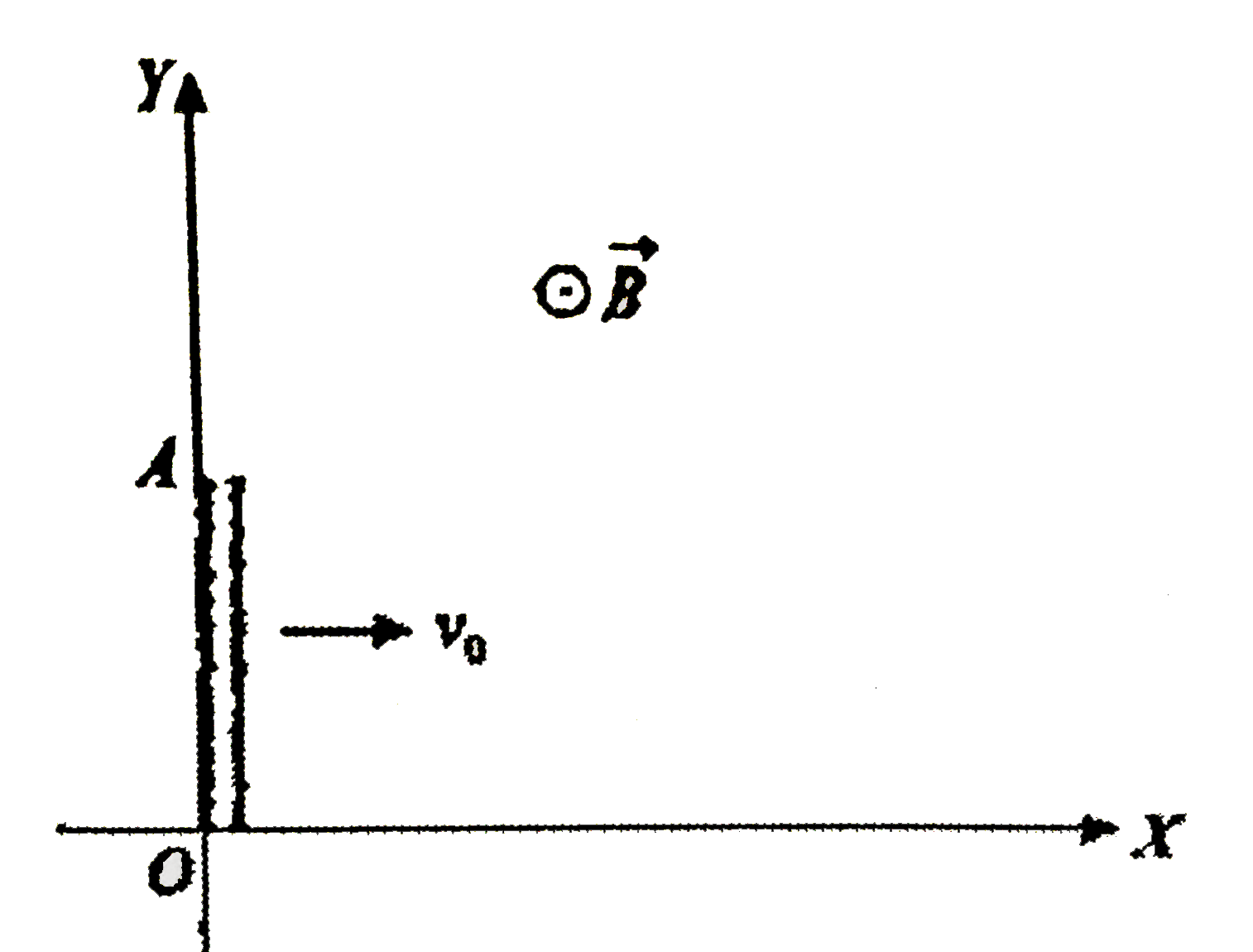
View SolutionFigure,5.36 shows a conductor OA of length I placed along y-axis with one end at origin. In this region a non-uiform magnetic field exist along `+Z`-direction of which magnitude depends only n its Y coordinate which is given as
`B=B_(0)(1+(y^(2))/(l^(2)))T`
If the conductor OA starts translating with velocity `vec(v)=v_(0)hat(i)`, find the EMF induced in conductor.
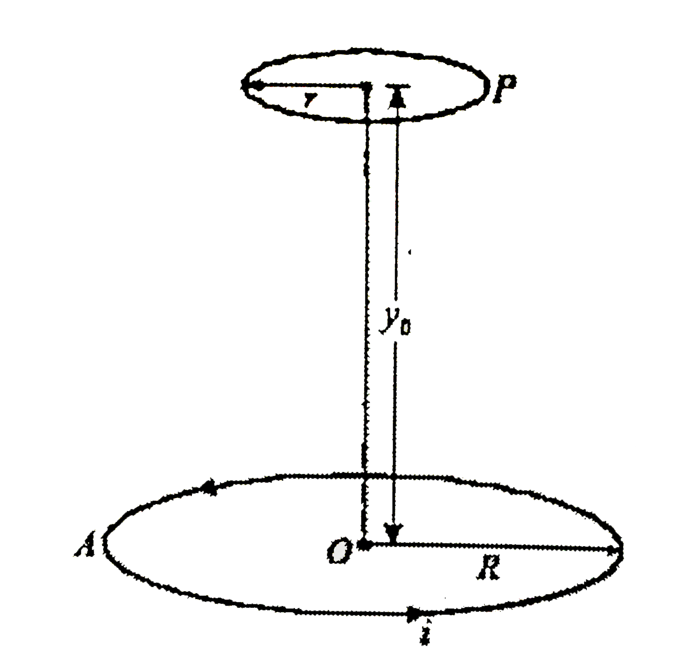
View SolutionA coil A of radius R and number of turns n carries a current i and it is placed in a horizontal plane. A small conducting ring P of radius `r (r lt lt R)` is placed at a height `y_(0)` above the centre of the coil A as shown in figure-5.38. Calculate the induced EMF in the ring when the ring in allowed to fall freely. Express the induced EMF as a function of instantaneous speed of the falling ring and its height above the center of the coil A.
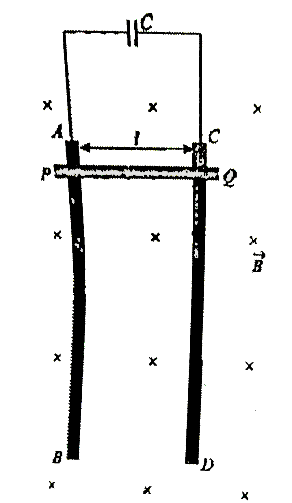
View SolutionFigure-5.39 shows two vertical smooth rails AB and CD separated by a distance l. Ends A and C are connected with capacitor of capacitance C. A rod PQ of mass m is horizontally kept in touch with both rails as shown. If it is released at t=0 and it remains in contact with rails during its fall, find the charge on capacitor as function of time. Neglect resistance of connecting wires and rails.
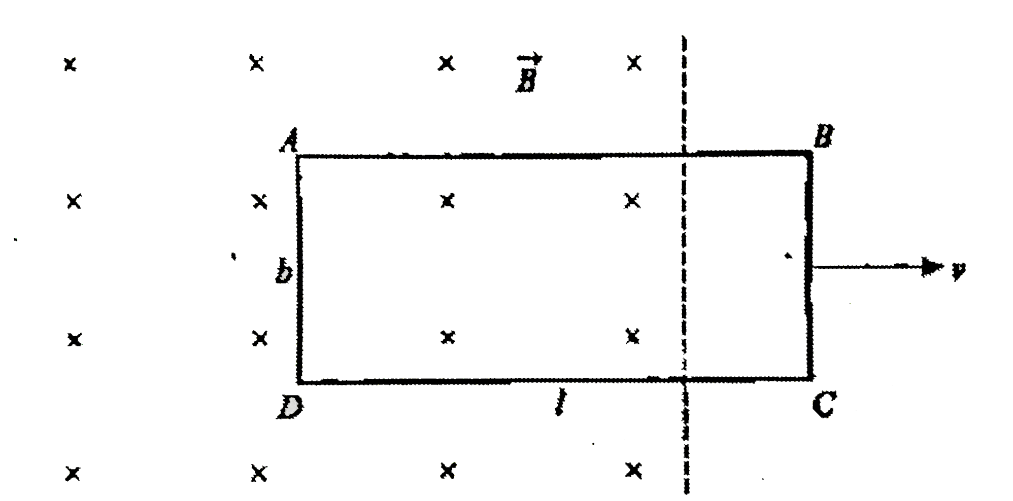
View SolutionFigure-5.41 shows a rectangular wire loop ABCD with length l and breadth b. the wire is having a resistance `lamda l` per unit length. If the loop is pulled out from the magnetic field at a uniform speed v as shown in fiure-5.00, find the potential difference across points of the loop `V_(B)-V_(C ) " and " V_(A)-V_(D)`.
View SolutionA metal rod of mass `m` can rotate about a horizontal axis `O`, sliding along a circular conductor of radius `a` (fig). The arrangment is located in a unifrom magnetic field of induction `B` directed perpendicular to the ring plane. The axis and the ring are connected to an emf source to form a circuit of resistance `R`. Neglecting the friction, circuit induction and ring resistance, find the law according to which the source and must very to make the rod rotate with a constant angular velocity `omega`.

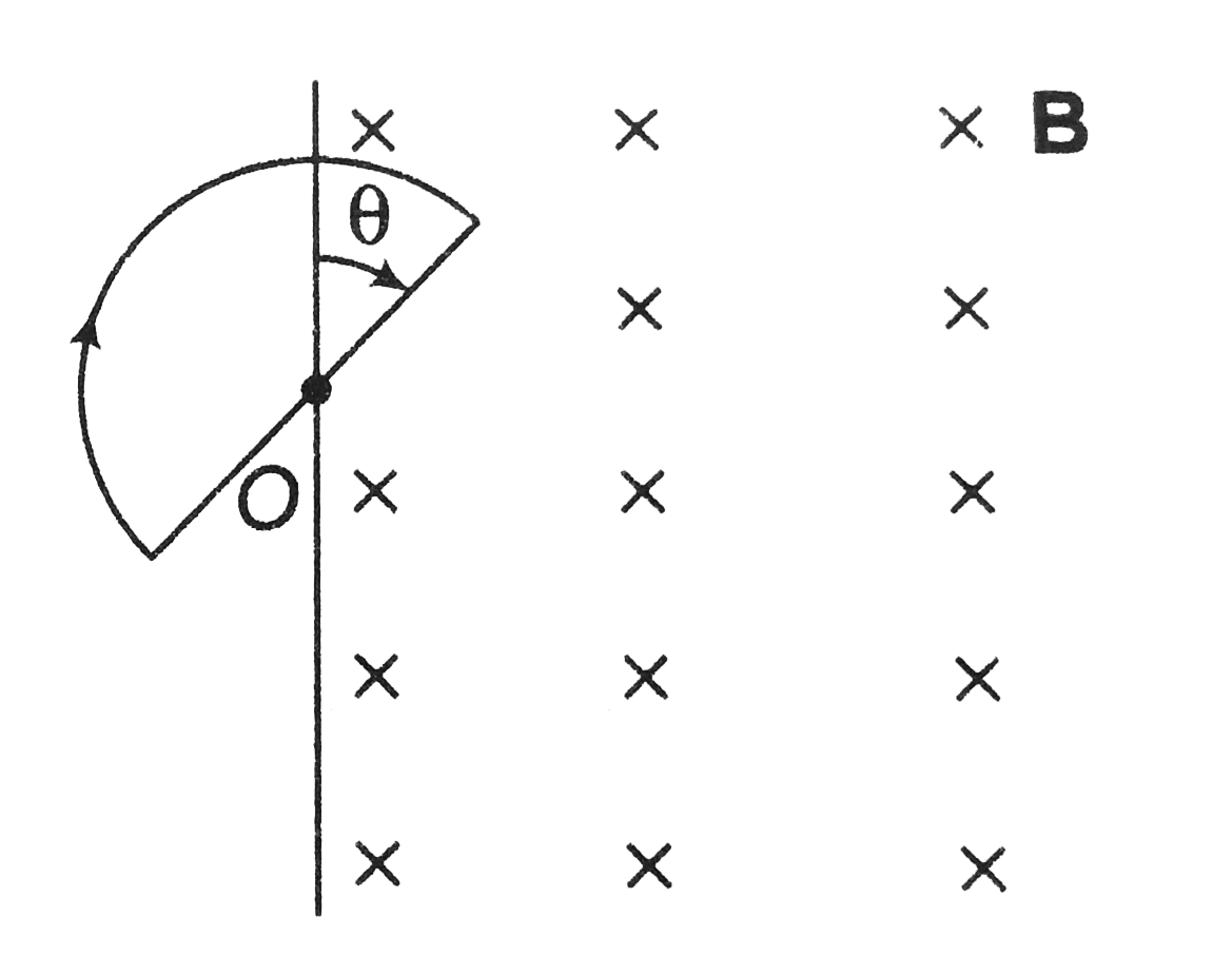
View SolutionA wire loop enclosing as semicircle of radius `R` is located on the boudary of uniform magnetic field `B`. At the moment `t=0`, the loop is set into rotation with a costant angular acceleration `alpha` about an axis `O` coinciding with a line of vector B on the boundary. Find the emf induced in the loop as a function of time. Draw the approximate plot of this function.The arrow in the figure shows the emf direction taken to be positive.
View SolutionA conducting light string is wound on the rim of a metal ring of radius `r` and mass `m`. The free end of the string is fixed to the ceiling. A vertical infinite smooth conducting plane is always tangent to the ring as shown in the figure. A uniform magnetic field Bis applied perpendicular to the plane of the ring. The ring is always inside the magnetic field. The plane and the strip are connected by a resistance `R`. When the ring is released, find
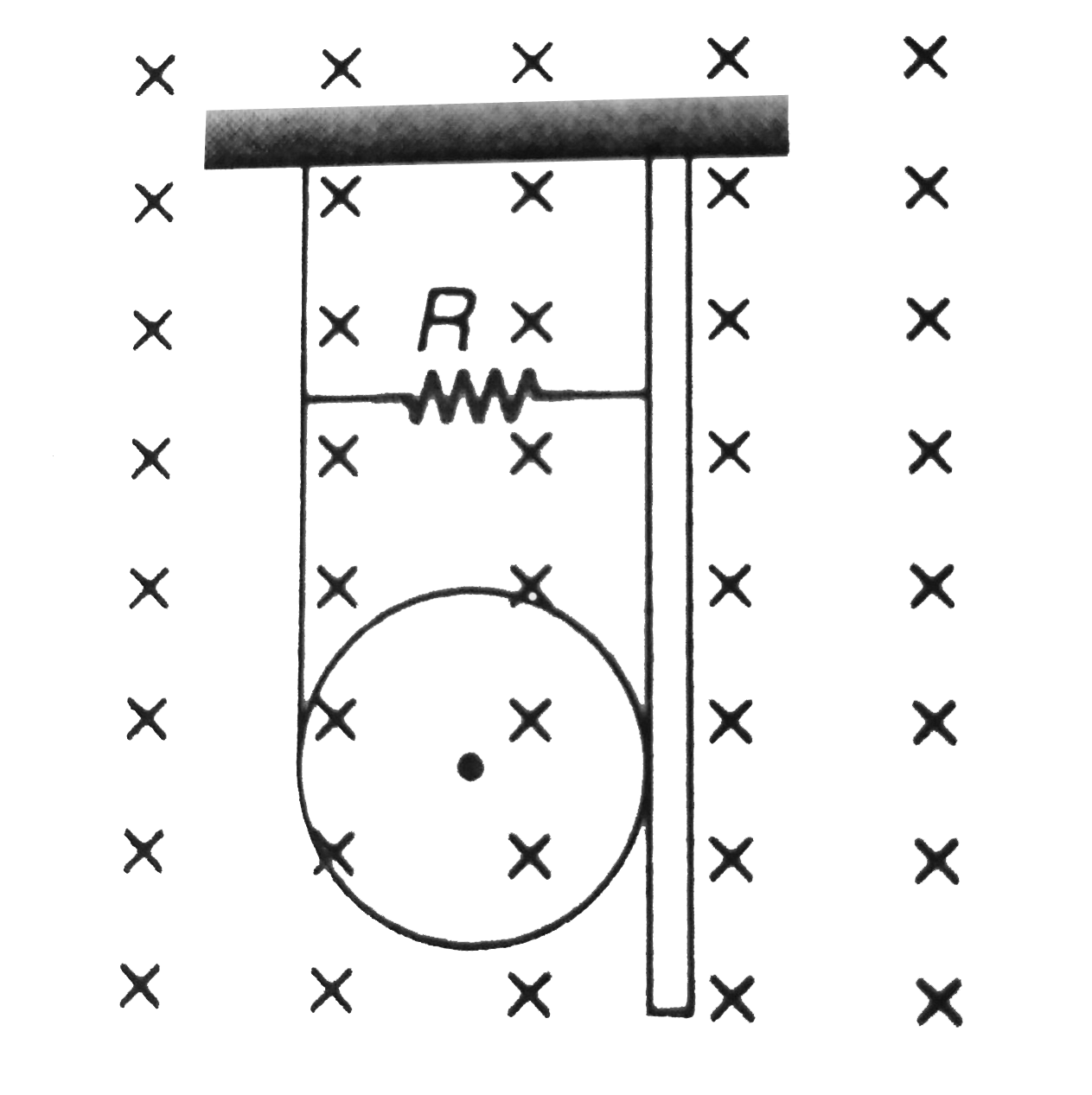
a. the curent in the resistance `R` as as function of time.
b. the terminal velocity of the ring.
View SolutionTwo concentric coplanar circular loops made of wire with resistance per unit length `10^(-4)Omega//m`, have diameters 0.2 m and 2m. A time varying potential difference (4+2.5t) volt is applied to the larger loop. Calculate the current in the smaller loop.
View SolutionA current `I = 3.36(1 +2t) xx 10^(-2)` A increase at a steady state in a long staight wire. A small circular loop of radius `10^(-3)` m has its plane parallel to the wire and is placed at a distance of 1 m from the wire. The resistance of loop is `8.4 xx 10^(-4) (Omega)`. Find the approximate value of induced current in the loop.
View SolutionA long straight solenoid of cross-sectional diameter d and with n turns per unit of its length has a round turn of copper wire of cross-sectional area A and density `rho` is tightly put on its winding. Find the current flowing in the turn if the current in the solenoid winding is increased with a constant rate I ampere per second.
View SolutionFor the situation described in figure, the magnetic field changes with time according to
`B=(2.00t^3-4.00t^2+0.8)t` and `r_2=2R=5.0cm`
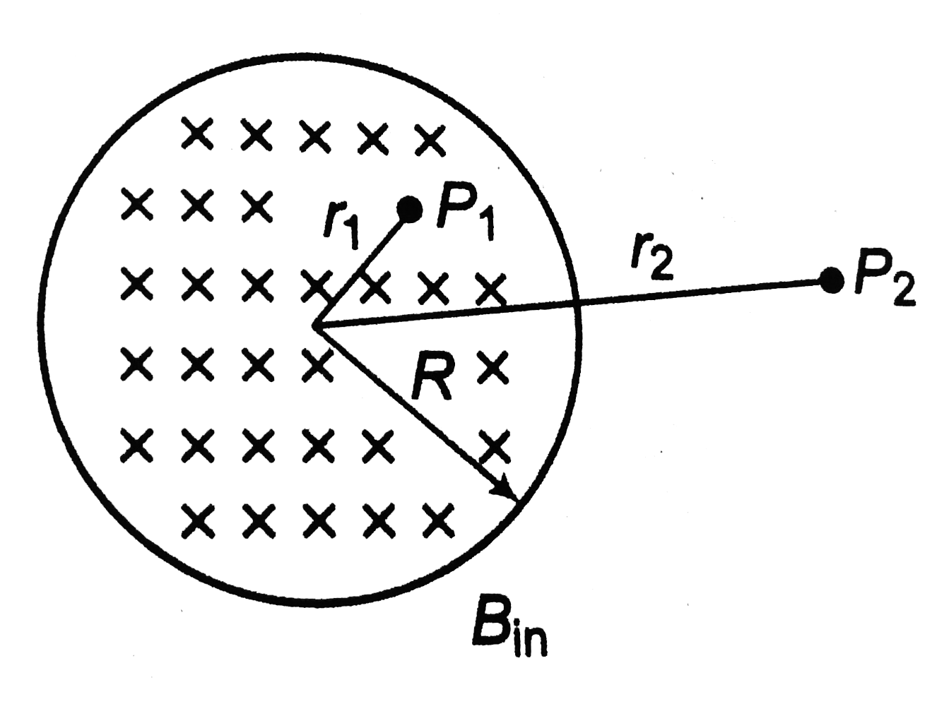
(a) Calculate the force on an electron located at `P_2` at `t = 2.00 s`
(b) What are the magnitude and direction of the electric field at `P_1` when `t = 3.00 s` and `r_1= 0.02 m`.
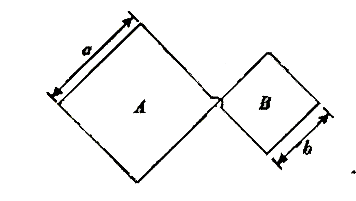
View SolutionA plane loop shown in figure-5.71 is shaped in the from of two squares with sides a and b and it is introduced into a uniform magnetic field at right angles, to the loop's plane. The magnetic induction varies with time as `B=B_(0) sin omega`t. find the amplitude of the current induced in the loop if its resistance per unit length is equal to r. the induction of the loop is negligible.
View SolutionFigure-5.72 shows a conducting loop of which semi-circular part lies in the magnetic induction B which varies with time, given as
`B=at^(3)+ct^(3)+fT`
The wire is having a resistance `Romega//m`. Find current in loop at time t=2s.
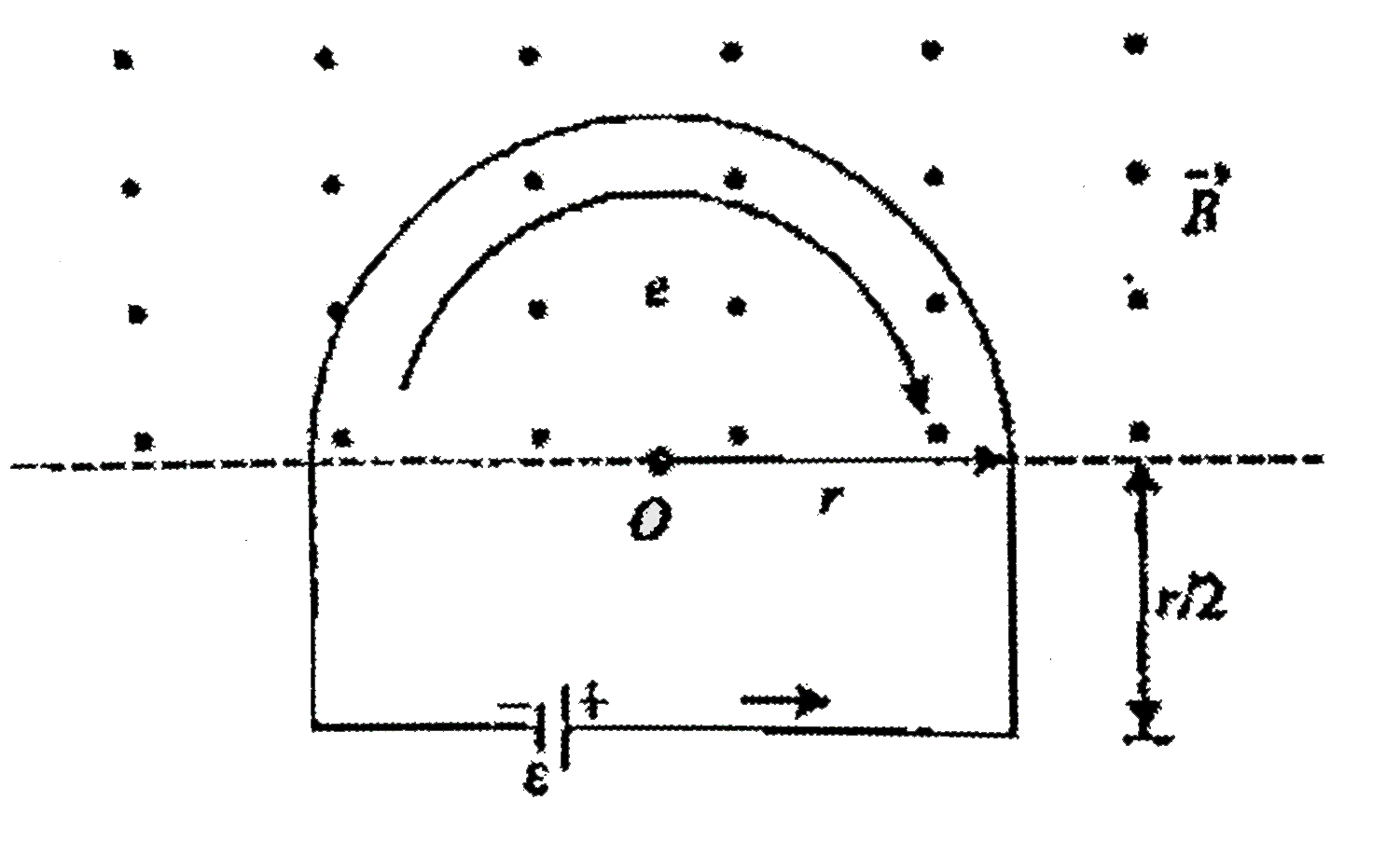
View SolutionA thin non-conducting ring of mass `m` carrying a charge `q` can freely rotate about its axis. At the initial moment the ring was at rest and no magnetic field was present. Then a practically unifrom magnetic field was switched on, which was perpendicular to the planeof the ring and increased with time according to a certain law `B (t)`, Find the angluar velocity `omega` of the ring as a function of the induction `B(t)`.
View SolutionAn infinitesimal bar magnet of dipole moment `M` is pointing and moving with speed `v` in the `x`-direction. A closed circular conducting loop of radius a and negligible self-inductance lies in the `y-z` plane with its centre at `x=0` and its axis coinciding with `x`-axis. find the force opposing the motion of the magnet, if the resistance of the loop is `R` . Assume that the distance `x` of the magnet from the centre of the loop is much greater than a .
View SolutionA closed coil having 50 turns, area `300cm^(2)`, is rotated from a position where it plane makes an angle of `45^(@)` with a magnetic field of flux density 2.0T to a position perpendlcular to the field in a time of 0.1s. What is the average EMF induced in the coil ?
View SolutionHow many meters of a thin wire are required to manufacture a solenoid of length `l_(0) = 100 cm` and inductance `L = 1.0 mH` if the solnoid's cross -sectional diameter is condiserably less than its length ?
View SolutionThe inductor shown in figure has inducance `0.54 H` and carries a current in the direction shown thast is decreasing at a uniform rate `(di)/(dt)=0.03A//s`.

a. Find the self induced emf
b. Which emf of the inductor a ro b is at a higher potential?
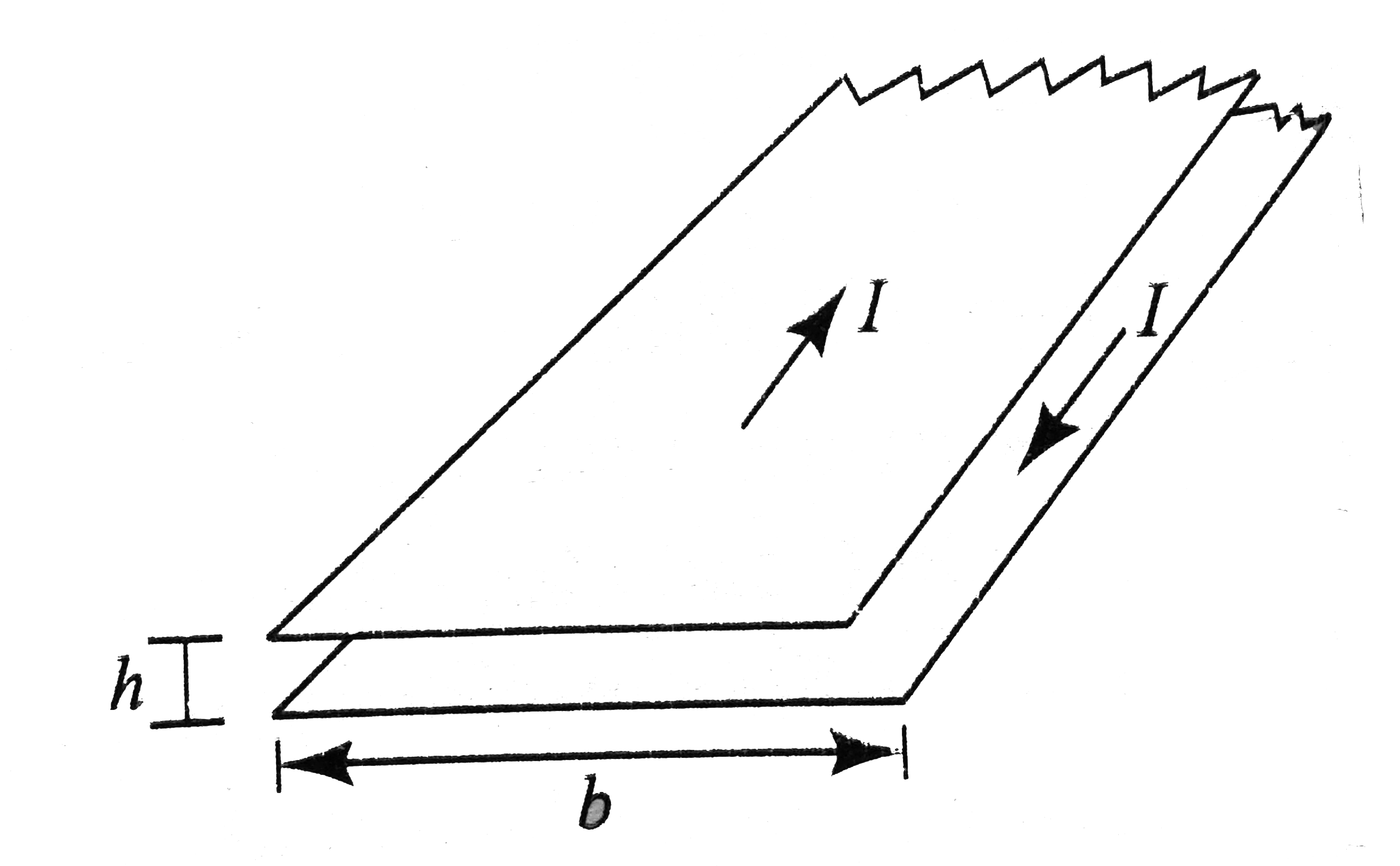
View SolutionCalculate the inductance of a unit length of a double tape line as shows in Fig if the tapes are separated by a distance `h` which is considerably less than their width `b`.
View SolutionCalculate the inducatance of a doughunt solenoid whose inside radius is equal to `b` and cross-section has the form of a square with side `a`. The solenoid winding consists of `N` turns. The space inside the solenoid is filled up with unifrom paramagnetic having permeability `mu`.
View SolutionAn iron core is inserted into a solenoid 0.5 m long with 400 turns per unit length. The area of cross-section of the solenoid is `0.001m^(2)`. (a) Find the relative permeability of the core when a current of 5 A flows through the solenoid winding. Under these conditions, the magnetic flux through the cross-section of the solenoid is `1.6xx10^(-3)` Wb. (b) Find the inductance of the solenoid under these conditions.
View SolutionA solenoid has an inductance of `10H` and a resistance of `2Omega`. It is connected to a `10V` battery. How long will it take for the magnetic energy to reach `1//4` of its maximum value?
View SolutionCalculate the time constant `tau` of a straight solenoid of length `l` having a single layer winding of copper wire whose total mass is equal to `m` . The cross-sectional diameter of the solenoid is assumed to be considerably less than its length. Given density of copper `p_(0)` and resistivity `p` .
View SolutionA battery of emf `E` and of negligible internal resistance is connected in a `L-R` circuit as shown in figure. The inductor has a piece of soft iron inside it. When steady state is reached in the piece of soft iron is abruptly pulled out suddenly so that the inductance of the inductor decreases to `nL` with `nlt1` with battery remaining connected. Calculate.
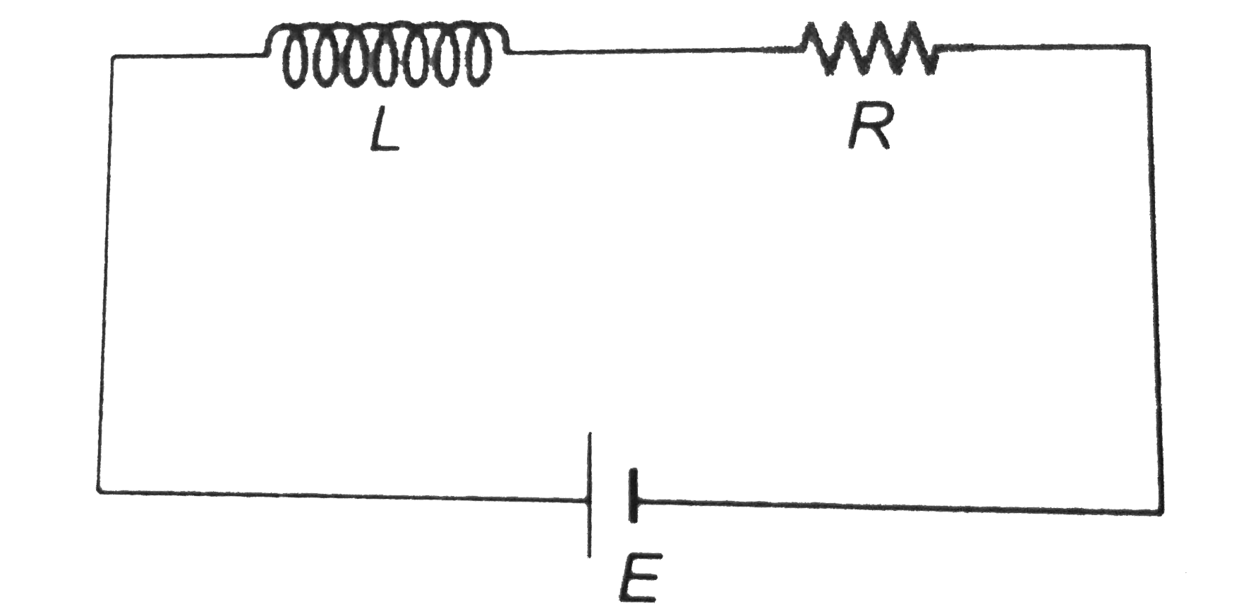
a. Current as a function of time assuming `t=0` at the instant when piece is pulled.
b. the work done to pull out the piece.
c. thermal power generated in the circuit as as function of time.
d. power supplied by the battery as a function of time.
HOW TO PROCEED When the inductance of an inductor is abruptly changed, the flux passing through it remains constant.
`phi =` constant
`:. Li =` constant `(L = (phi)/(i))`
View SolutionA thin wire ring of radius a and resitance `r` is located inside a long solenoid is equal to `l`, its cross-sectional radius , to `b`. At a certain moment the solenoid was connected to a source of a constant voltage `V`. The total resistance of the circuit is equal to `R`. Assuming the the radial force acting per unit length of the ring.
View SolutionA section of an electrical circuit XY is shown in figure-5.100 which carries a current of 5A which is decreasing at the rate of `10 A//s`. Find the potential difference `V_(y)-V_(x')`

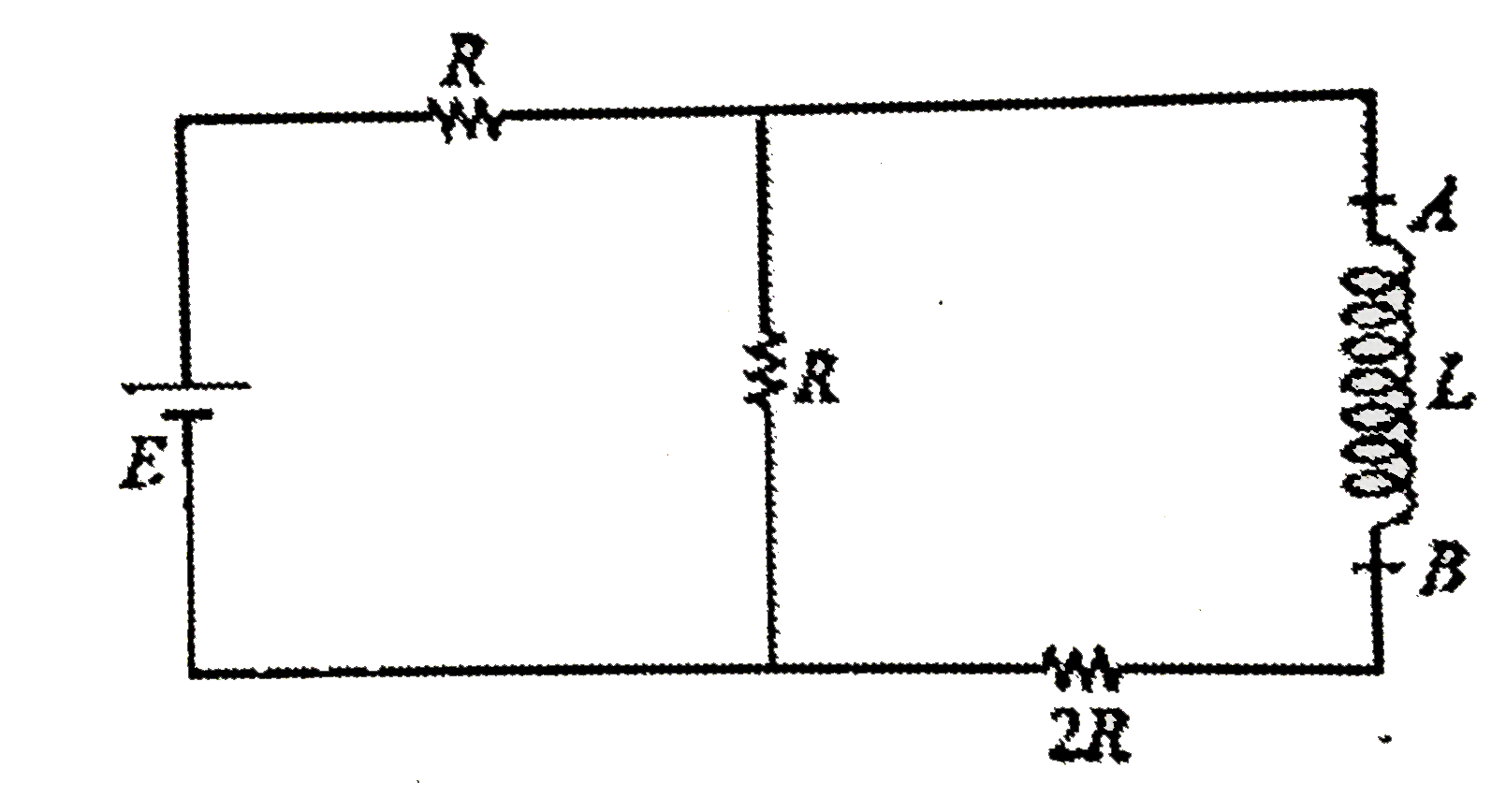
View SolutionFigure-5.102 shows a RL circuit. If at t-0 switch is closed, find the current in inductor as a function of time.
View SolutionA solenoid of resistance `50Omega` and inductance `80H` is connected to a `200V` battery. How long will it take for the current to reach `50%` of its final equilibrium value? Calculate the maximum energy stored.
View SolutionThe current in a coil of self inductance 2.0 henry is increasing according to `i= 2 sin t^(2)` ampere. Find the amount of energy spent during the period when the current changes from 0 to 2 amp.
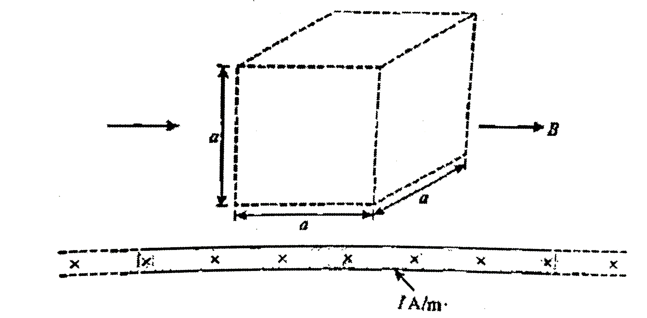
View SolutionFind the magnetic field energy in a cubical region of edge 'a' above a large current carrying sheet carrying a uniform linear current density I `A//m`.
View SolutionWhat inductance would be needed to store `1.0 kWh` of energy in a coil carrying a `200 A` current. `(1kWh=3.6xx10^6J)`
View SolutionA thin uniformly charged ring of radius `a = 10 cm` rotates about its axis with an angular velocity `omega = 100 rad//s`. Find the ratio of volume energy densities of magnetic and electric fields on the axis of the ring at a point removed from its centre by a distance `l = a`
View SolutionA `10 H` inductor carries a current of `20A`. How much ice at `0^@C` could melted by the energy stored in the magnetic field of the inductor? Latent heat of ice is `22.6xx10^I3J//kg`
View SolutionA coil of inductance `L = 2.0 mu H` and resitance `R = 1.0 Omega` is connected to a source of constant `emf E = 3.0 V`. A resistance `R_(s) = 2.0 Omega` is connected in parallel with the coil. Find the amount of heat generated in the coil after the swich `Sw` is disconnecied. The internal resistance of the source is negligible.

View SolutionIn cirucit shown in figure-5.111, find the current through battery just after closing the switch and after a long time in steady state.
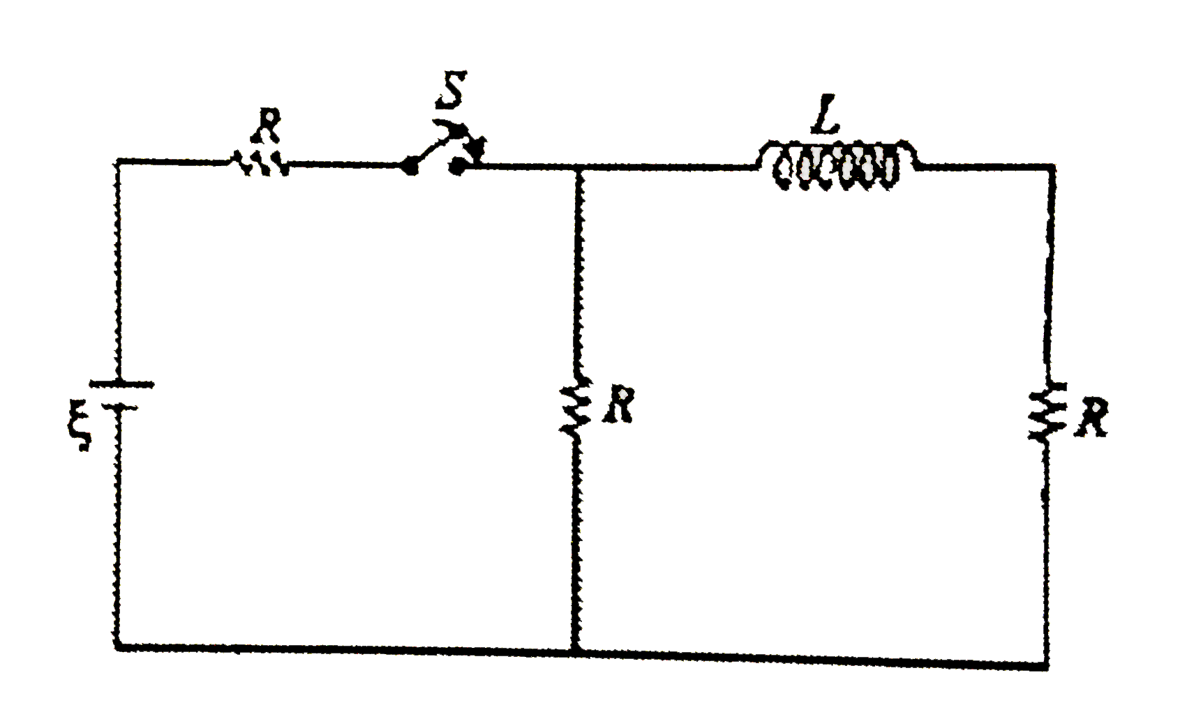
View SolutionFor the ciruit shown in figure `E=50V`, `R_1=10Omega, R_2=20Omega, R_3=30Omega` and `L=2.0 mH`. Find
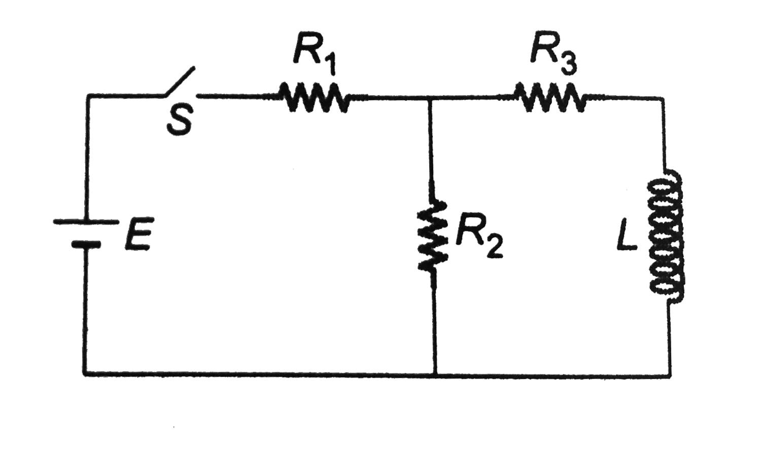
a. Immediately after switch `S` is closed
b. A long time after `S` is closed.
c. Immediaately after S is reopened
d. A long time after `S` is reopened.
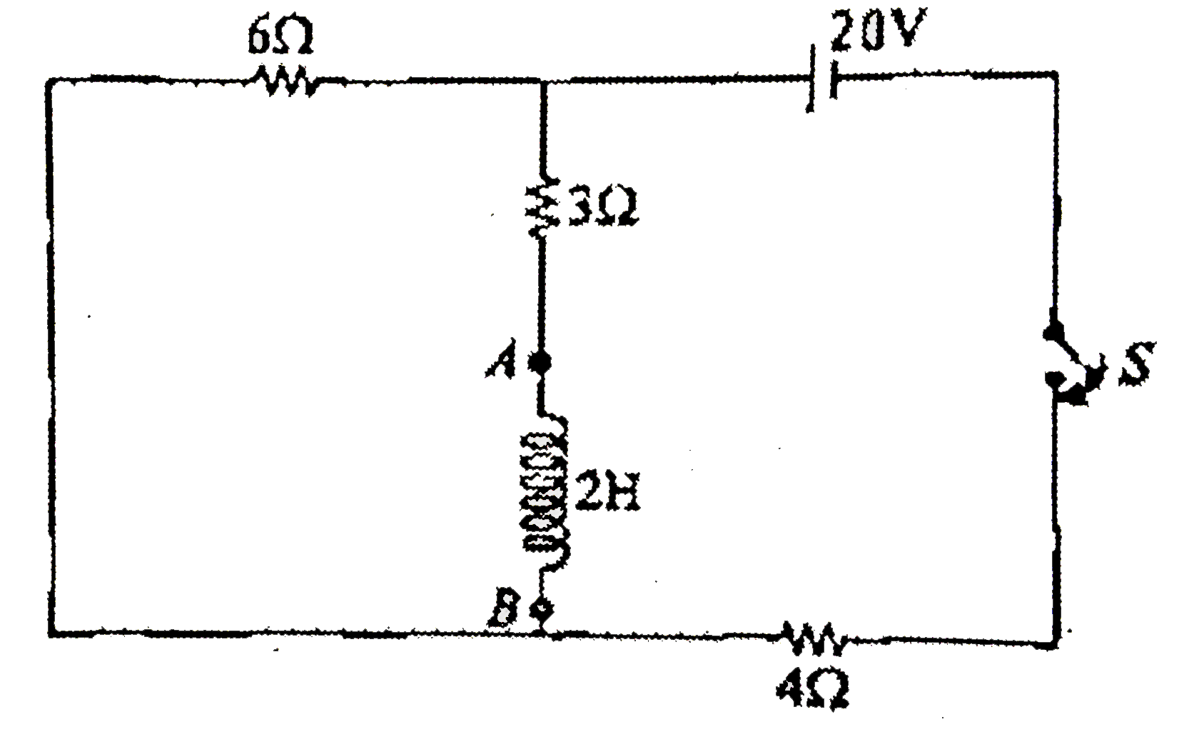
View SolutionIn the circuit shown in figure-5.115, find the current in inductor as a function of time if switch is closed at t=0.
View SolutionIn a process of current decay in an inductor through a resistance, if in time t, current falls to `eta` times `(eta lt 1)` the initial value, find the time constant of circuit.
View SolutionA coil of 100 turns and 1cm radius is kept coaxially within a long solenoid of 8 turns per cm and 5 cm radius. Find the mutual inductance.
View SolutionCalculate the mutual inductance of a long straight wire and a rectangular frame with sides `a` and `b`. The frame and the wire lie in the same plan, with the side `b` being closent to the wire, separated by a distance `l` from it and oriented parallel to it.
View SolutionAn inductor of inductance L is cut in three equal parts and two of these parts are interconnected (a) in series, (b) in parallel. Assuming the mutual inductance between the parts to be negligible, calculate the inductance of the combination of the combination in both the cases.
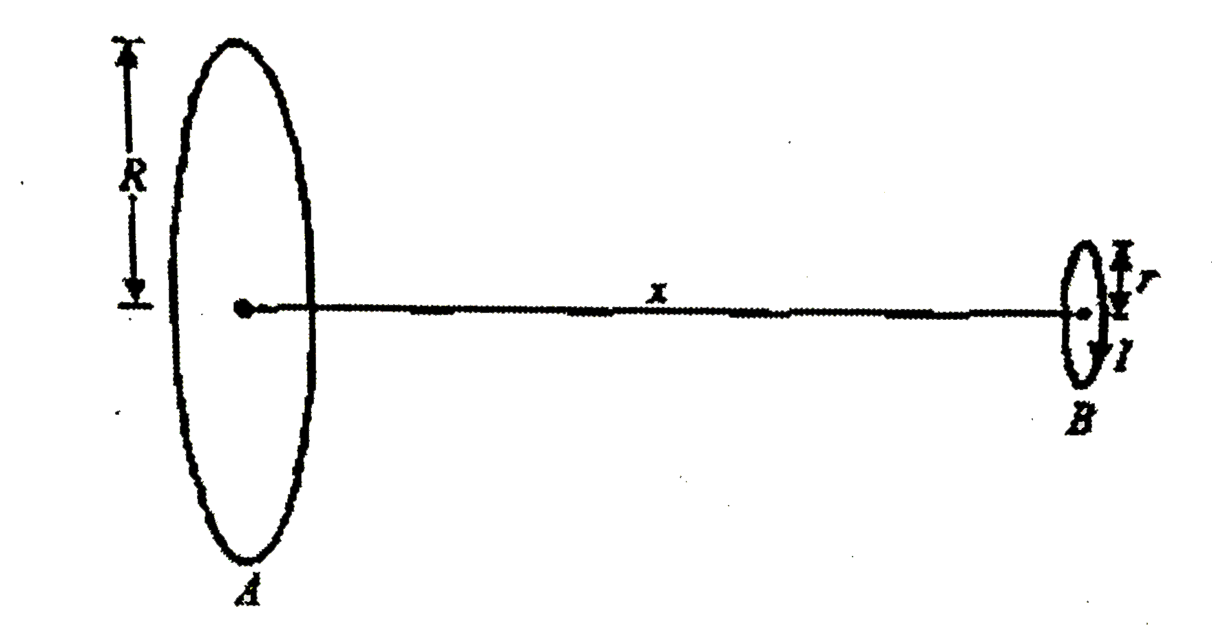
View SolutionFigure-5.136 shows two coaxial coils of radii r and R `(R gt gt r)` kept at large separation x`(x gt gt R)`. Calculate the magnetic flux passing through coil A due to a current I in coil B.
View SolutionIn the circuit shown in Fig. `emf E` , a resistance `R`, and coil inductances `L_(1)` and `L_(2)` are known. The internal resistance of the source and the coil resistances are neglible. Find the steady-state currents in the coils after the swich `Sw` was shorted.

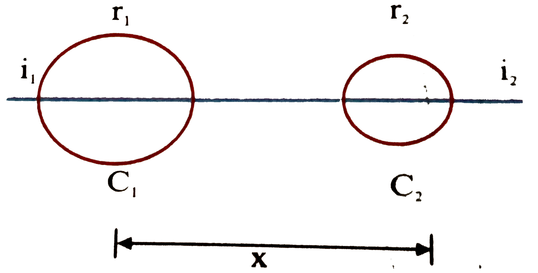
View SolutionTwo coaxial circular loops of radius `0.5 m` and `5 xx 10^(-2)m` are separated by a distance `0.5 m` and carry currents `2 A` and `1 A` respectively. The force between the loops due to mutual induction is
View Solution
Illustrative Example questions and complete solutions for chapter ELECTROMAGNETIC INDUCTION AND ALTERNATING CURRENT of GK PUBLICATIONS PHYSICS (HINGLISH) of Class 12