Level 2 from ARIHANT PHYSICS Chapter 4 ELECTROMAGNETIC INDUCTION for Class 12
| Class 12 | PHYSICS |
| Chapter | ELECTROMAGNETIC INDUCTION |
| ARIHANT PHYSICS | Level 2 |
| Medium | English |
| Academic Year | 2023-2024 |
Question 1
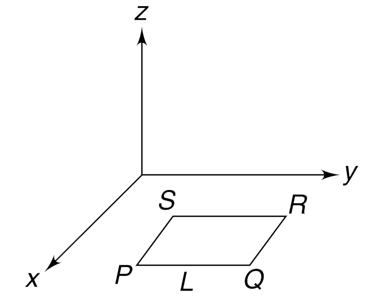
A rectangular conducting loop PQRS is kept in xy plane with its adjacent sides parallel to x and y axes. A mag- netic field →B is switched on in the region which varies in posi- tion and time as →B=[B0sin(ky–ωt)]ˆk . It was found that the emf induced in the loop is always zero. Express the length (L) of the loop in terms of constant k and ω.
 View Solution
Question 2
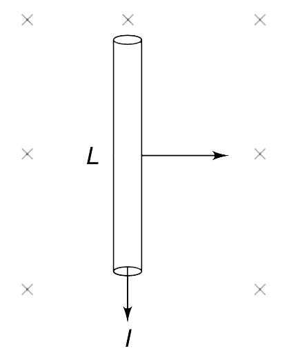
A conducting rod of length L is carrying a constant current I. There exists a magnetic field B perpendicular to the rod. Due to the magnetic force the rod moved through a distance x in a direction perpendicular to the field (B) as well as its own length. The rod acquires a kinetic energy. A student says that a magnetic force ILB acted on the rod and it performed a work W=ILBx on the rod. But we know that magnetic force is always perpendicu- lar to the velocity of the charge and it cannot perform work on a moving charge. Which agency has actually spent energy to impart kinetic energy to the rod?
 View Solution
Question 3
In a rectangular circuit ABCD a capacitor having capacitance C=20μF is charged to a potential difference of 100 V. Resistance of circuit is R=10Ω. Another rectangular conducting loop PQRS is kept side by side to the first circuit with sides AB and PQ parallel and close to each other. The length and width of rectangle PQRS is a = 10 cm and b = 5 cm respectively and AB as well as BC is large compared to a. PQ is located near the centre of side AB with d = 5 cm. The loop PQRS has 25 turns and the wire used has resistance of 1Ωm–1. The switch S is closed at time t = 0. Neglect self inductance of loops.
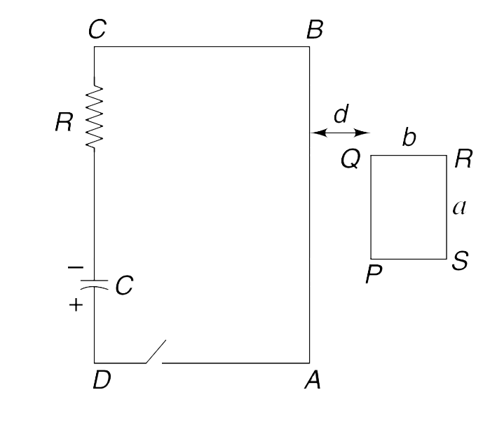
(a) Find the current in ABCD at t=200μs.
(b) Find the current in PQRS at t=200μs. View SolutionQuestion 4
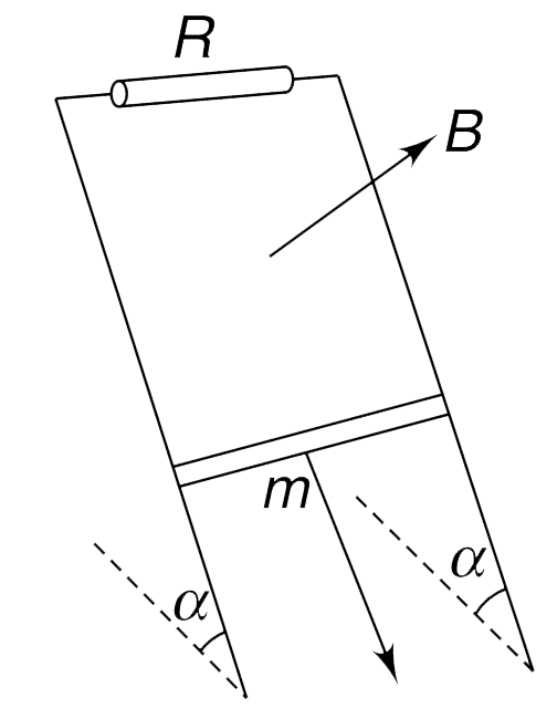
A copper connector of massm, starting from rest, slides down two conducting bars set at angle α to the horizontal, due to gravity (see figure). At the top the bars are interconnected trhough a resistance R. The separation between the bars is equal to l. The system is located in uniform magnetic field of induction B, perpendicular to the plane in which the connectr slides. The resistance of the bars the connector and the sliding contacts, as well as the self inductance of the loop, are assumed to be negligible. The coefficient of friction between the connector and the bars is equal to 12 and α
(a) Find the steady-state velocity of the connector.
(b) How will your answer differ if the magnetic field was in opposite direction.
 View Solution
Question 5
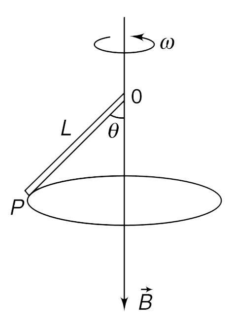
A conducting rod (OP) of length L rotates in form of a conical pendulum with an angular velocity ω about a fixed vertical axis passing through its end O. There is a uni- form magnetic field B in vertically downward direction. The rod makes an angle θ with the direction of the magnetic field. Calculate the emf induced across the ends of the rod. Which end is positive?
 View Solution
Question 6
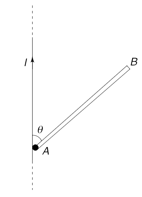
A conducting rod AB of mass M and length L is hinged at its end A. It can rotate freely in the vertical plane (in the plane of the Figure). A long straight wire is vertical and carrying a current I. The wire passes very close to A. The rod is released from its vertical position of unstable equilibrium. Calculate the emf between the ends of the rod when it has rotated through an angle θ (see Figure).
 View Solution
Question 7
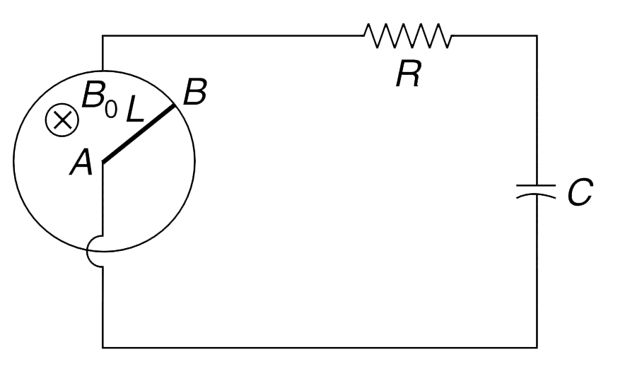
A perfectly conducting ring of radius L is kept fixed on a horizontal surface. A vertical uniform magnetic field B0 exists in the region. A conducting rod (AB) of length L is hinged at the centre of the ring at A and its other end (B) touches the ring. The ring and the end A of the rod are connected to an external circuit having resistance R and capacitance C. The rod is made to rotate at a constant angular speed ω0. Neglect friction and self inductance of the circuit.
(i) Find work done by the external agent in rotating the rod by the time the capacitor acquires a charge q0.
(ii) Find heat generated in resistance R by the time the capacitor acquires a charge q0.
 View Solution
Question 8
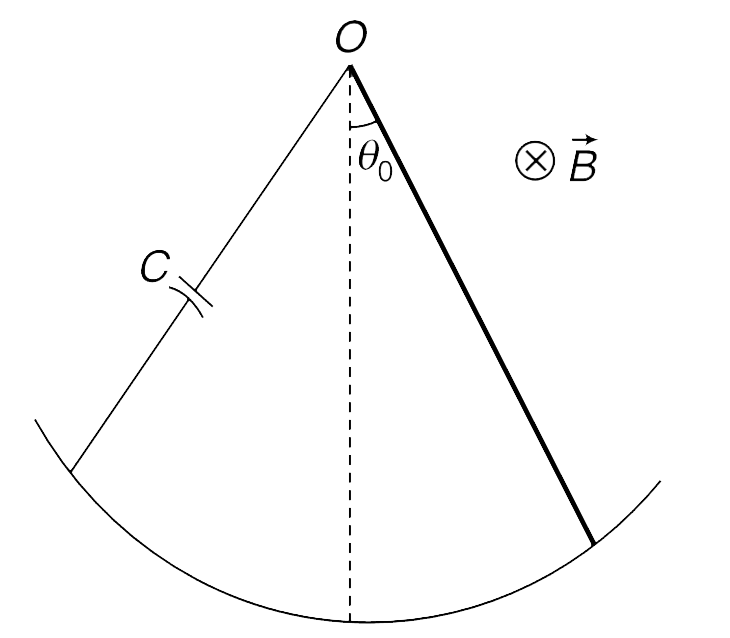
A conducting rod of mass M and length L can oscillate like a pendulum in a vertical plane about point O. The lower end of the rod glides smoothly on a circular conducting arc of radius L. The circular arc is connected to point O of the rod through a capacitor of capacitance C. The entire device is kept in a uniform horizontal magnetic field B directed into the plane of the Figure. Disregard resistance of any component. The rod is deflected through a small angle θ0 from vertical position and released at time t = 0.
(a) Write the deflection angle (θ) of the rod as a function of time t.
(b) If the capacitor is replaced with a resistor what kind of motion do you expect? Give qualitative description only.
 View Solution
Question 9
Two identical thin circular, metal plates are at a small separation d. They are connected by a thin conducting rod (AB) of length d. Each plate has area A. An ideal spring of stiffness k is connected to a rigid support and midpoint of rod AB as shown in the figure. Spring is made of insulating material. The system is on a smooth horizontal surface. The entire region has a uniform vertical upward magnetic field B.
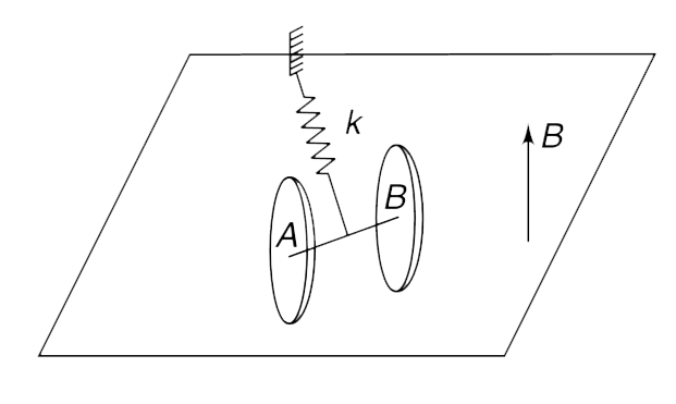
The discs are pulled away from the support and released. Find time period of oscillations. Mass of the two disc plus rod system is M. Neglect any eddy current. View SolutionQuestion 10
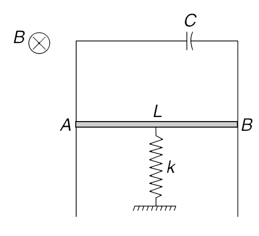
Two metal bars are fixed vertically and are connected on top by a capacitor of capacitance C. A sliding conductor AB can slide freely on the two bars. Length of conductor AB is L and its mass is m. It is connected to a vertical spring of force constant k. The conductor AB is released at time t = 0, from a position where the spring is relaxed. Taking initial position of the conductor as origin and downward direction as positive x axis, write the x co-ordinate of the conductor as a function of time. The entire space has a uniform horizon- tal magnetic field B. Neglect resistance and inductance of the circuit and assume that the bar AB always remains horizontal.
 View Solution
Question 11
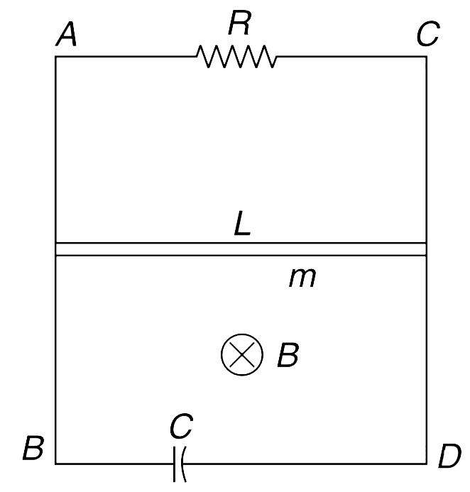
Two long fixed parallel vertical conducting rails AB and CD are separated by a distance L. They are connected by resistance R and a capacitance C at two ends as shown in the figure. There is a uniform magnetic field B directed horizon- tally into the plane of the figure. A horizontal metallic bar of length L and mass m can slide without friction along the rails. The bar is released from rest at t = 0. Neglect resistance of bar and rails and also neglect the self inductance of the loop.
(a) Find the maximum speed acquired by the bar after it is released.
(b) Find the speed of the bar as a function of time t.
 View Solution
Question 12
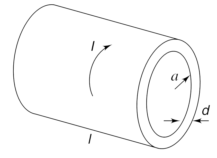
A hollow cylinder made of material of resistivity ρ has length a and wall thickness d(l>>a>>d). A current I flows through the cylinder in tangential direction and is uniformly distributed along its length.
(a) Find the emf developed along the circumference of the cylinder if the current changes at a rate dldt=β
(b) Assume that no external source is present and the current at time t = 0 is I0. The current decays with time. Write I as a function of time.
 View Solution
Question 13
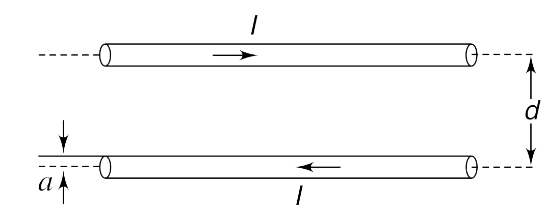
A long straight wire of cross sectional radius a carries a current I. The return current is carried by an identical wire which is parallel to the first wire. The centre to centre distance between the two wires is d. Find the inductance (L) of a length x of this arrangement. Neglect magnetic flux inside the wires.
 View Solution
Question 14
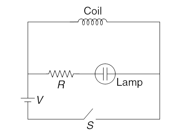
In the circuit shown in the figure the neon lamp lights up if potential difference across it becomes 60 V and goes out if the potential difference falls below 30 V. The inductor coil has a very small resistance and emf of the cell is V = 4 volt. The lamp does not light when the switch is closed. The neon light flashes once when the switch is opened. Explain why?
 View Solution
Question 15
Determine the mutual inductance of a toroid and an infinite straight wire located along the central axis of the toroid. The toroid has a rectangular cross section with inner and outer radii a and b respectively. The width of the rectangular cross section parallel to the straight wire is h. Total turns in the toroid is N.View SolutionQuestion 16
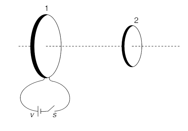
Two coils – 1 and 2 – are mounted co axially as shown in the figure. The resistance of the two coils are R1 and R2 and their self inductances are L1 and L2 respectively. Switch S is closed at time t = 0 to connect the coil 1 to an ideal cell of emf V. It is observed that by the time current reaches its steady value in coil 1, the quantity of charge that flows in coil 2 is Q0. Calculate the mutual inductance (M) between the two coils.
 View Solution
Question 17
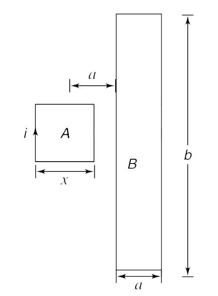
A rectangular conducting loop B has its side lengths equal to b and a(<<b). In the plane of the loop there is another very small loop A in shape of a square of side length x. Loop A is placed symmetrically with respect to B with its centre at a distance a from one of its longer side (see Figure). There is a current (i) in loop A which is made to increase at a constant rate of didt=αAs–1. Calculate the emf induced in the bigger loop.
 View Solution
Question 18
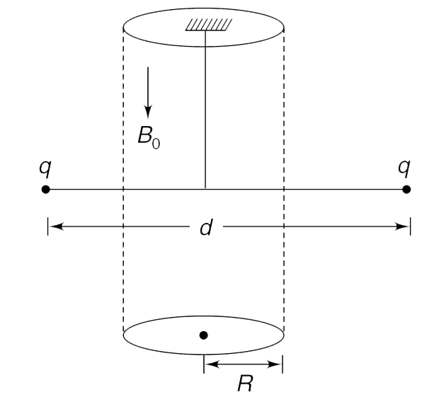
Two identical small balls, made of insulting material are attached to the ends of a light insulating rod of length d. The rod is suspended from the ceiling by a thin torsion free fibre as shown in figure. Each ball is given a charge q. There is a uniform magnetic field B0, pointing vertically down, in a cylindrical region of radius R. The fibre is along the axis of the cylindrical region. The system is initially at rest. Now the magnetic field is suddenly switched off. Calculate the angular velocity acquired by the system. Each ball has mass m.
 View Solution
Question 19
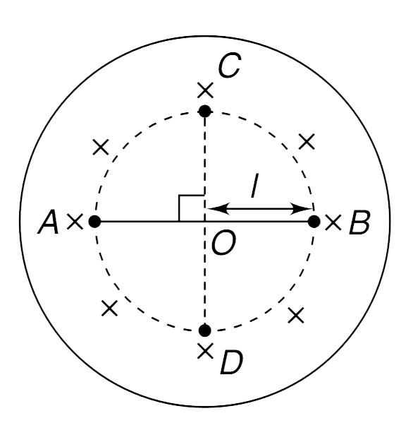
A massless non conducting rod AB of length 2l is placed in uniform time varying magnetic field confined in a cylindrical region of radius (R>l) as shown in the figure. The center of the rod coincides with the centre of the cylin- drical region. The rod can freely rotate in the plane of the Figure about an axis coinciding with the axis of the cylinder. Two particles, each of mass m and charge q are attached to the ends A and B of the rod. The time varying magnetic field in this cylindrical region is given by B=B0[1−t2] where B0 is a constant. The field is switched on at time t=0. Consider B0=100T,l=4cmqm=4π100C/kg. Calculate the time in which the rod will reach position CD shown in the figure for th first time. Will end A be at C or D at this instant ?
 View Solution
Question 20
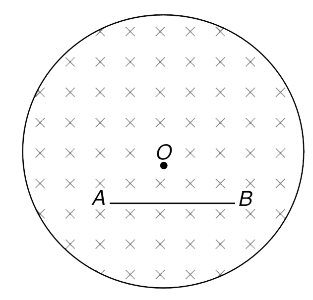
A cylindrical region of radius R is filled with a uniform magnetic field B as shown in the figure. A metal wire (AB) of length L is placed inside the field such that its ends are symmetrically located with respect to the centre (O) of the circular cross section of the region. If the magnetic field is changed at a rate dBdt the emf induced in the metal wire is e. Find change in value of ε if the wire is displaced by a small distance ΔL parallel to its own length. Assume that the wire remains inside the field region.
 View Solution
Question 21
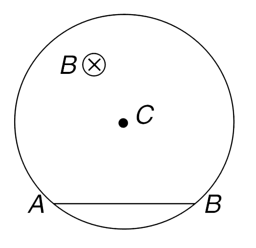
cylindrical volume of radius R has a uniform axial magnetic field B, which is increasing at a rate of dBDt=αTs−1. A chord (AB) of the circular cross section of the cylindrical region has length L.Calculate the line integral of induced electric field (∫BA→E→dl) as one moves along the chord from A to B. Try to find the answer without actually performing the integration. Is the value of integral same if one moves along the arc from A to B ?
 View Solution
Question 22
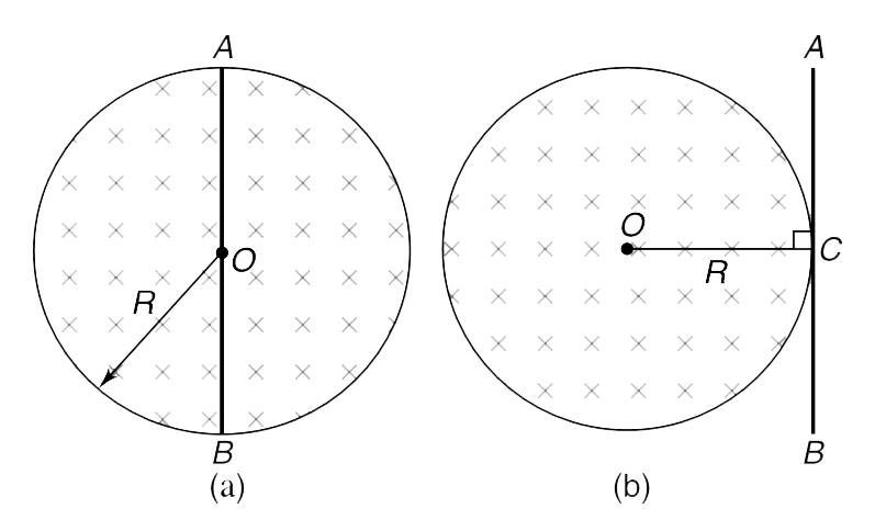
A uniform magnetic field B exists in a circular region of radius R. the field is perpendicular to the plane and is increasing at a constant rate of dBdt=α. There is a straight conducing rod AB of length 2R. Find the emf induced in the rod when it is placed as shown in figure (a) & (b). Point C is midpoint of the rod in figure (b)
 View Solution
Question 23
A thin beam of n identical positively charged particle are constrained to move in a circular orbit of radius R in a particle accelerator. Each particle has charge q and mass m and the current in the circular orbit is I0. The magnetic flux through the circular path is made to increases at a constant rate of βWbs–1. Calculate the current after the particles complete one turn. View SolutionQuestion 24
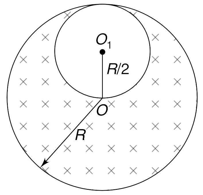
There is a long cylinder of radius R having a cylindrical cavity of radius R/2 as shown in the figure. Apart from the cavity, the entire space inside the cylinder has a uniform mag- netic field parallel to the axis of the cylinder. The magnetic field starts changing at a uniform rate of dBdt=kT/s. Find the induced electric field at a point inside the cavity.
 View Solution
Question 25
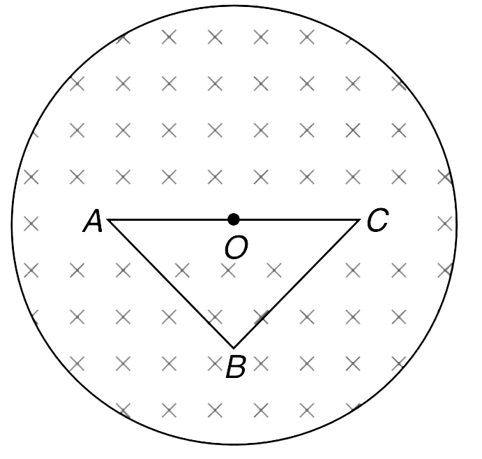
A uniform magnetic field B exists in a region of circular cross section of radius R. The field is directed perpendicularly into the plane of the figure. There is a tri- angular circuit ABC made of a uniform wire placed in the circular region. The triangle is a right angled isosceles tri- angle with equal sides AB=BC=l. The hypotenuse AC has its midpoint at the centre of the circle. Electrical resistance of the triangular circuit per unit length isr0l. If the magnetic field is changed at a constant rate of dBdt=α, find the potential difference between points C and A and that between B and A.
 View Solution
Question 26
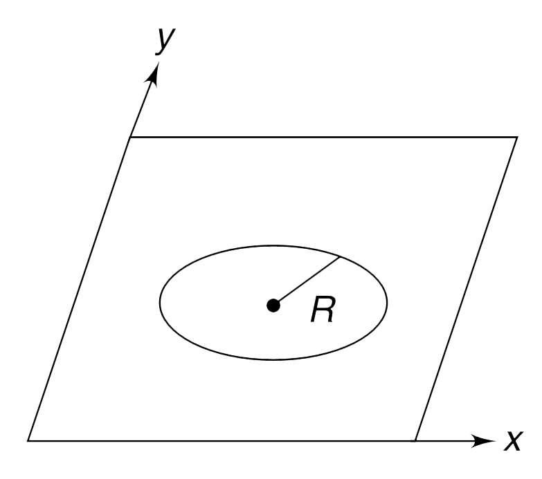
A conducting ring of mass m=πkg and radius R=12m is kept on a flat horizontal surface (xy plane). A uniform magnetic field is switched on in the region which changes with time (t) as →B=(2ˆj+t2ˆk)T. Resistance of the ring is r=πΩ and g=10ms−2.
(a) Calculate the induced electric field at the circumference of the ring at the instant it begins to topple.
(b) Calculate the heat generated in the ring till the instant it starts to topple.
 View Solution
Question 27
A tightly wound solenoid of length l and cross sectional area A1 is partly inserted co-axially into another tightly wound solenoid of length l and cross section A2(>A1). The centres of the two solenoids are separated by x(<l). Assume that A2<<x2,A2<<l2. Calculate the total magnetic field energy inside the solenoid when both of them carry same current (I) in the same sense. Number of turns in each solenoid is N. View SolutionQuestion 30
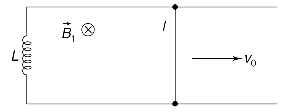
Two ends of an inductor of inductance L is connected to two parallel conducting rails. A conducting wire of length (that is equal to separation between the rails) can slide on the rails without friction. The wire has mass m. It is projected with a velocity v0 parallel to the rails (see Figure). Neglect self inductance and resistance of the loop.
(a) Find velocity of the wire as a function of time.
(b) Write current through the wire at time t.
(c) Find speed of the wire as a function of its displacement.
(d) Is the current in the conductor zero when it stops? If no, find this current .
(e) Will the conductor move after it stops?
 View Solution
Question 31
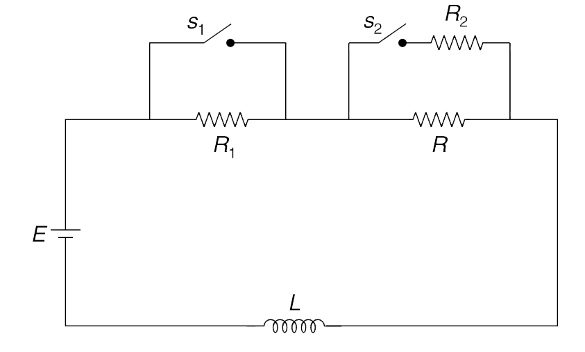
In the circuit shown in Figure, switch S1 is kept closed and S2 open for a long time. Resistance R1=1000R and R2=10−3R.
(a) Switch S1 is opened at time t = 0. Write the current and potential drop across R1 immediately after S1 is opened. What will be value of current after a long time?
(b) Switch S2 is closed (S1 is already closed since long) at time t = 0. Write current and potential drop across R2 immediately after this operation. Write current through the inductor as a function of time.
 View Solution
Question 32
A ring is made of a nearly superconducting mate- rial. Inductance of the ring is L=0.5H. A current allowed to decay in the ring was observed to remain constant for a month. The instrument used to measure current could detect any change if it is greater than 1%. Estimate the resistance of the ring considering it as a L R circuit with decaying current. View SolutionQuestion 33
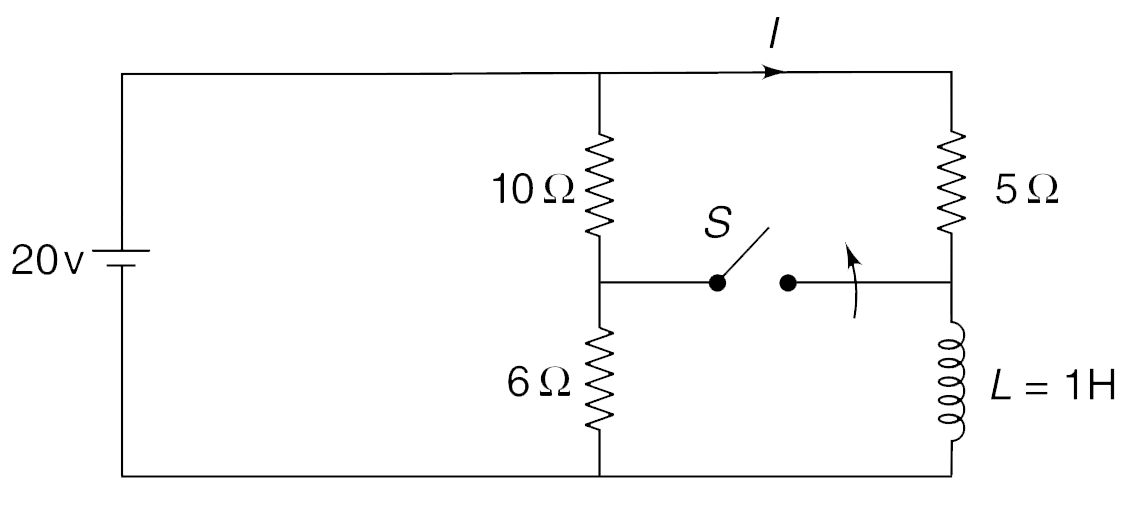
In the circuit shown, the switch ‘S’ has been closed for a long time and then opens at t = 0.
(a) Find the current through the inductor just before the switch is opened.
(b) Find the current I a long time after the switch is opened.
(c) Find current I as a function of time after the switch is opened. Also write the current through the cell as a function of time.
 View Solution
Question 35
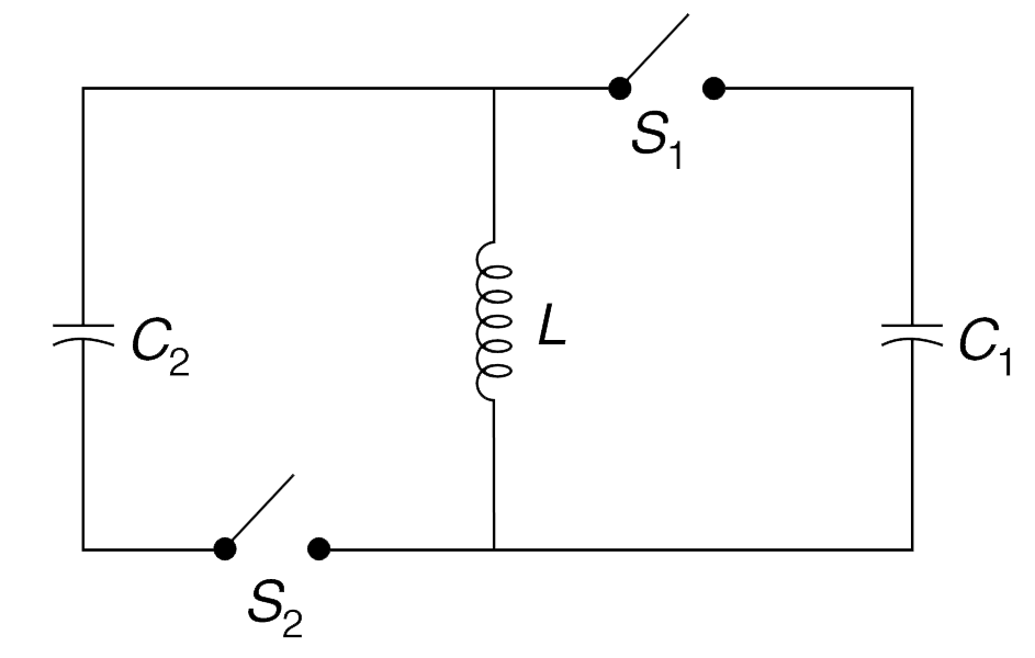
The circuit shown in the figure is used to transfer energy from one capacitor to another. Initially capacitor of capacitance C1=C0 is charged to a potential difference of V0. Switch S1 is closed at time t = 0. After some time S1 is opened and S2 is closed simultaneously. At time t=T,S2 was opened and it was found that the potential difference across capacitor of capacitance C2=C09 was 3V0. Find the smallest possible value of time T. The coil has inductance L. Assume no resistance.
 View Solution
Question 36
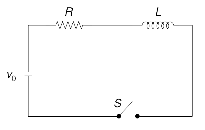
A pure inductor coil having inductance L is connected to a resistance R and a cell of emf V0 as shown in the figure. Switch ‘S’ is closed at t = 0.
(a) Plot the variation of voltage across the resistance and the inductance as a function of time
(b) Find the time (t1) when the two curves, obtained in (a) intersect.
(c) A student decides to start counting time from the instant the current becomes half its maximum value. Show the graphical plot of current vs time as obtained by this student.
 View Solution
Question 37
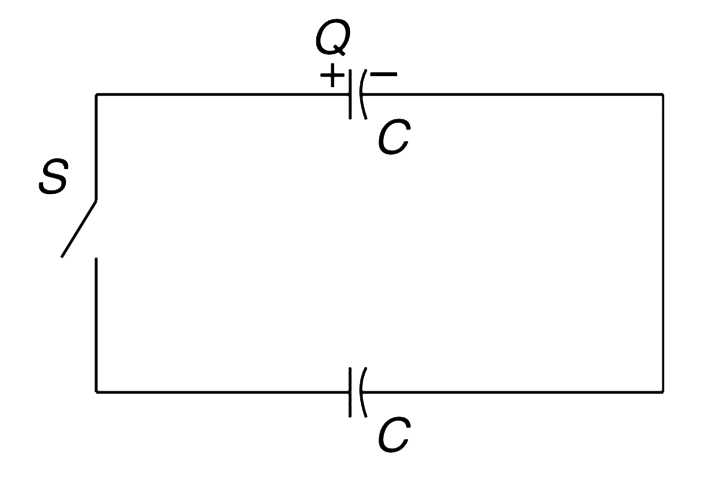
The circuit shown in figure has two identical capacitors one of which carries a charge Q and the other is having no charge. Switch S is closed. Find the maximum value of current in the circuit if self inductance of the loop is L and each capacitance C. Neglect resistance of the loop.
 View Solution
Question 38
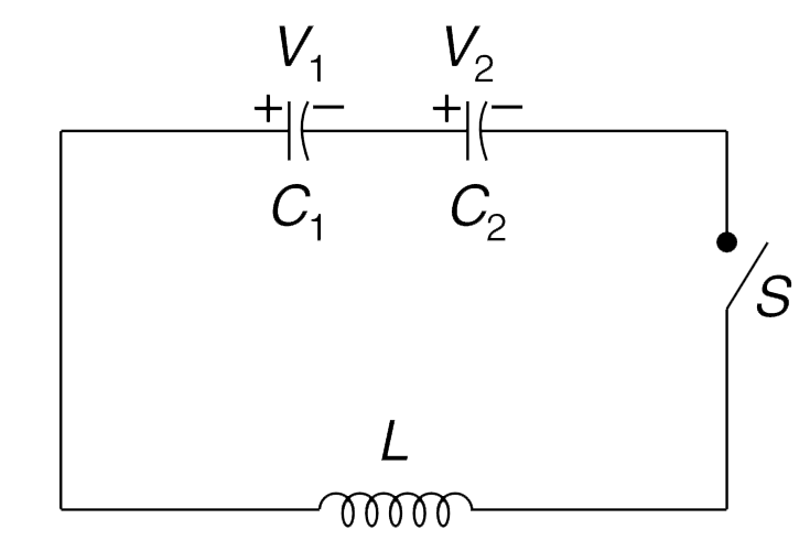
The capacitors shown in the circuit have capacitance C1=C and C2=3C and they have been charged to potenitals V1=2V0 and V2=3V0 respectively. Switch S is closed to connect them to the inductor L.
(a) Find the maximum current through the inductor
(b) Find potential difference across C1 and C2 when the current in the inductor is maximum.
 View Solution
Question 39
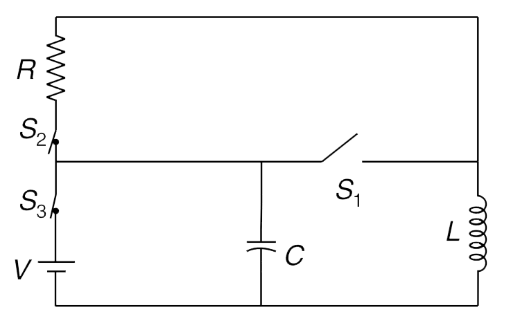
In the circuit shown in figure S1 is open and, S2 and S3 are closed. The circuit is in steady state. At time t = 0, switch S1 is closed and S2 and S3 are opened simultaneously. V=100volt,R=10Ω,C=100μF,L=0.03H
(a) Find the maximum charge that will appear on the capacitor at any time.
(b) Find the time at which the charge on the capacitor will become zero for the first time.
 View Solution
