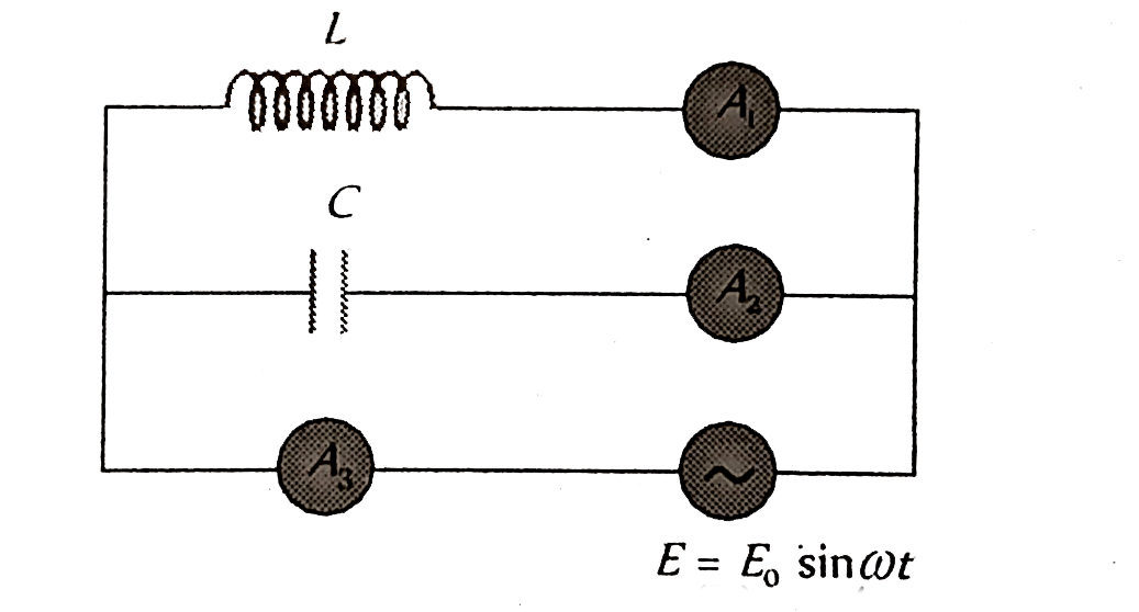
An inductor L and capacitor C are connected in the circuit as shown in fig. The frequency of the power supply is equal to the resonant frequency of the circuit. Which ammeter will read zero ?a A1 b A2 c A3 d None of these
The correct option c A3Explanation:The frequency matches resonance occurs. Given is parallel LC circuit. Hence parallel resonance will occur. In parallel resonance circuit current become zero. Hence ammeter A3 which is used to show total circuit current will read zero.
Related Solutions
An inductor L and a capacitor C are connected in the circuit as shown in the figure. The frequency of the power supply is equal to the resonant frequency of the circuit. Which ammeter will read zero ampere
 View Solution
An inductor L and a capacitor C are connected in the circuit as shown in the figure. The frequency of the power supply is equal to the resonant frequency of the circuit. Which ammeter will read zero ampere
 View Solution
An inductor of 10mH an a capacitor of 16mF are connected in the circuit as shown in figure The frequency of the power supply is equal to the resonant frequency of the circuit Which ammeter will read will zero ampere .
View SolutionAn inductor L and capacitor C are added to the circuit as shown in Figure IV.24. The frequency of the power supply is equal to the resonant frequency of the circuit. Which ammeter will have zero ampere reading?
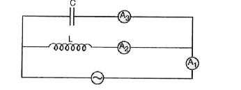
View SolutionAN inductor L, a capacitor C and A.C ammeters are connected in the circuit as shown. When the frequency of the oscillator is increased then at resonant frequency, the reading of ammeter
 View Solution
An inductance L and capacitor C are connected as shown in the figure. If the frequency of the charged source and the resonant frequency are equal, then which of the following ammeter will show zero reading?
View SolutionAn inductor L , a capacitor C and AC ammeters A_(1),A_(2) and A_(3) are connected in the circuit as shown. When the frequency of the oscillators is increased, then at resonant frequency, the reading of ammeter ?
View SolutionFigure below shows a capacitor C, an inductor L and a resistor R, connected in series to an a.c. supply of 220 V. The resonant frequency of the given RLC circuit.
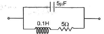
View SolutionIn the circuit shown in fig, the resonant frequency is
 View Solution
Resonant frequency of L-C circuit is :
View SolutionThe resonant frequency of an L - C circuit is
View SolutionA series L-C-R circuit with R = , L = 1.5 H and C = is connected to a variable frequency 200 V, AC supply. When the frequency of the supply equals the natural frequency of the circuit, what is the average power transfered to the circuit, what is the average power transfered to the circuit in one complete cycle ?
View SolutionA series L-C-R circuit with R = 20 Omega , L = 1.5 H and C = 35muF is connected to a variable frequency 200 V, AC supply. When the frequency of the supply equals the natural frequency of the circuit, what is the average power transfered to the circuit, what is the average power transfered to the circuit in one complete cycle ?
View SolutionWhen the frequency of the AC source in an LCR circuit equals the resonant frequency, the reactance of the circuit is zero. Does it mean that there is no current through the inductor or the capacitor?
View SolutionWhen the frequency of the AC source in an LCR circuit equals the resonant frequency, the reactance of the circuit is zero. Does it mean that there is no current through the inductor or the capacitor?
View SolutionWhen the frequency of the AC source in an LCR circuit equals the resonant frequency, the reactance of the circuit is zero. Does it mean that there is no current through the inductor or the capacitor?
View Solutionएक ट्रांजिस्टर ढोलक में अनुनादी परिपथ का प्रयोग किया गया है जिसमें प्रेरक L ( प्रतिरोध नगण्य ) और संधारित्र C को श्रंख्लाबंध्द जोड़ा गया है | इसमें आवृति f के दोलन पैदा होते है | यदि L को दुगुना कर दिया जाये तथा C को 4C में बदल दिया जाये, तो प्राप्त आवृति का मान हो जाएगा---
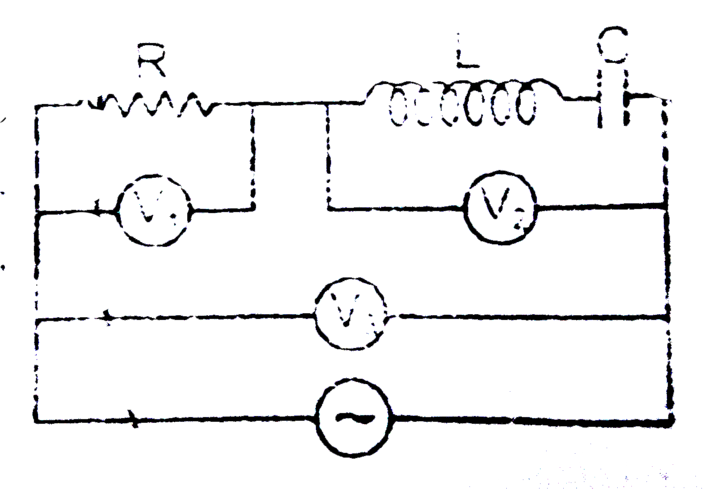
View SolutionA resistor , an inductor , a capacitor and voltmeters and are connected to an oscillator in the circuit as shown in the adjoining diagram.When the frequency of the oscillator is increased, upto resonance frequency, the voltmeter reading (at resonance frequency) is zero in the case of:
 View Solution
A resistor R , an inductor L , a capacitor C and voltmeters V_(1),V_(2) and V_(3) are connected to an oscillator in the circuit as shown in the adjoining diagram.When the frequency of the oscillator is increased, upto resonance frequency, the voltmeter reading (at resonance frequency) is zero in the case of:
View SolutionA resistor R, an inductor L, a capacitor C and voltmeters V_(1),V_(2) and V_(3) are connected to an oscillator in the circuit as shown in the adjoining diagram.When the frequency of the oscillator is increased, upto resonance frequency, the voltmeter reading (at resonance frequency) is zero in the case of:
 View Solution
