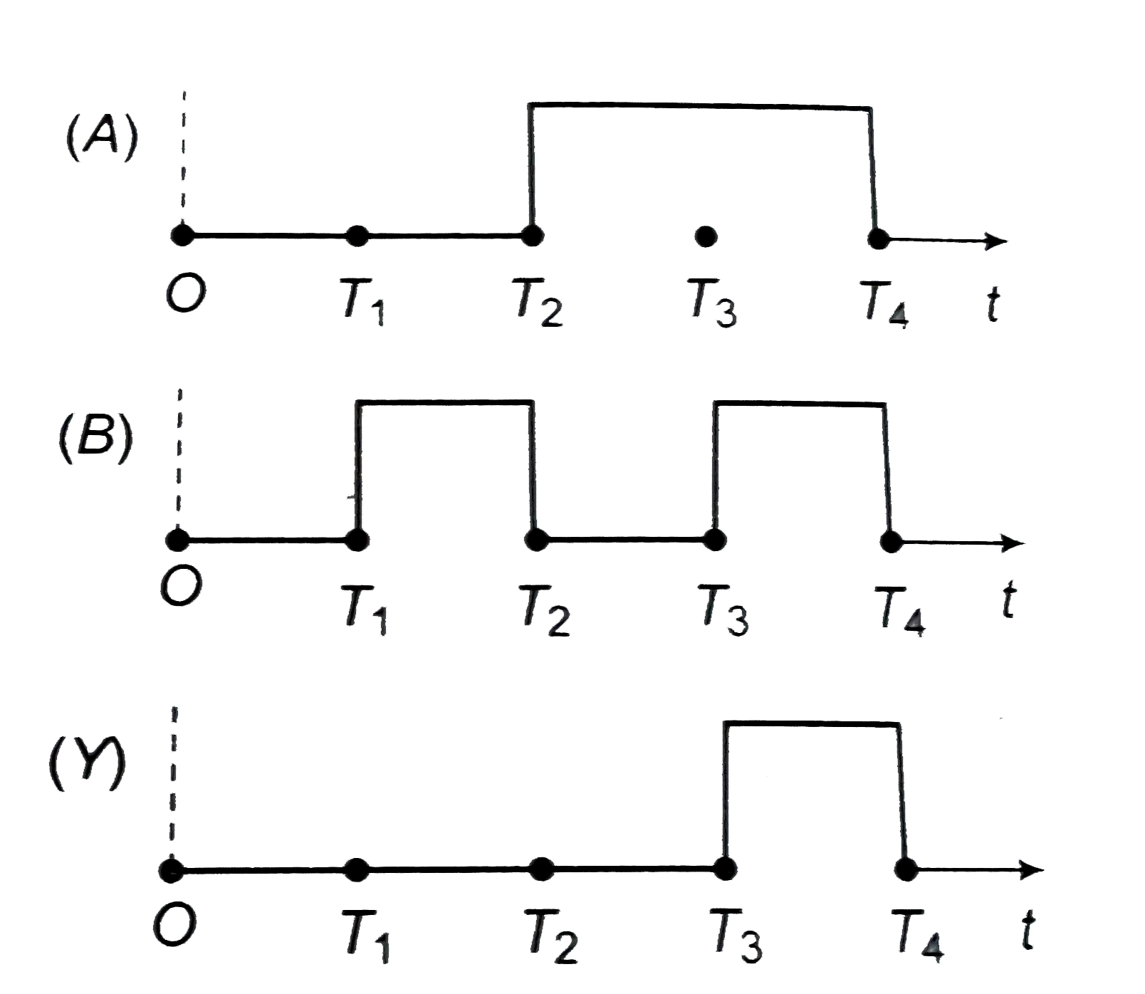
Draw the output wave form at X using the given inputs A and B for the logic circuit shown below. Also identify the logic operation performed by this circuit.
That is the logic operation is AND operation. Therefore output is 1 only when both inputs are 1. The output waveform is shown in figure.
Related Solutions
Draw the output waveform at X, using the given inputs, A and B for the logic circuit shown below. Also, identify the logic operation performed by this circuit.
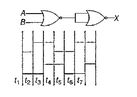
View SolutionDraw the output waveformed at X, using the given inputs A and B for the logic circuit shows below. Also, identify the logic operation performed by this circuit.

View SolutionDraw the output waveform X, using the given inputs A and B for the logic circuit shows below. Also, identify the logic operation performed by this circuit.

View SolutionDraw the output waveformed at X, using the given inputs A and B for the logic circuit shows below. Also, identify the logic operation performed by this circuit.

View SolutionDraw the output waveform X, using the given inputs A and B for the logic circuit shows below. Also, identify the logic operation performed by this circuit.

View SolutionDrawn the output waveform at X, using thye given inputs A and B for the logic circuit shown in Fig. Also identify the logic operation performed by this circuit.

View SolutionUsing the wave forms of the input A and B, draw the output waveform of the given logic circuit . Identify the logic gate obtained . Write also the truth table.
View SolutionUsing the wave forms of the input A and B, draw the output waveform of the given logic circuit . Identify the logic gate obtained . Write also the truth table.

View SolutionIdentify the logic operation performed by the circuit as shown in the figure.
View SolutionWrite the truth table for the logic circuit shown below and identify the logic operation performed by circuit.
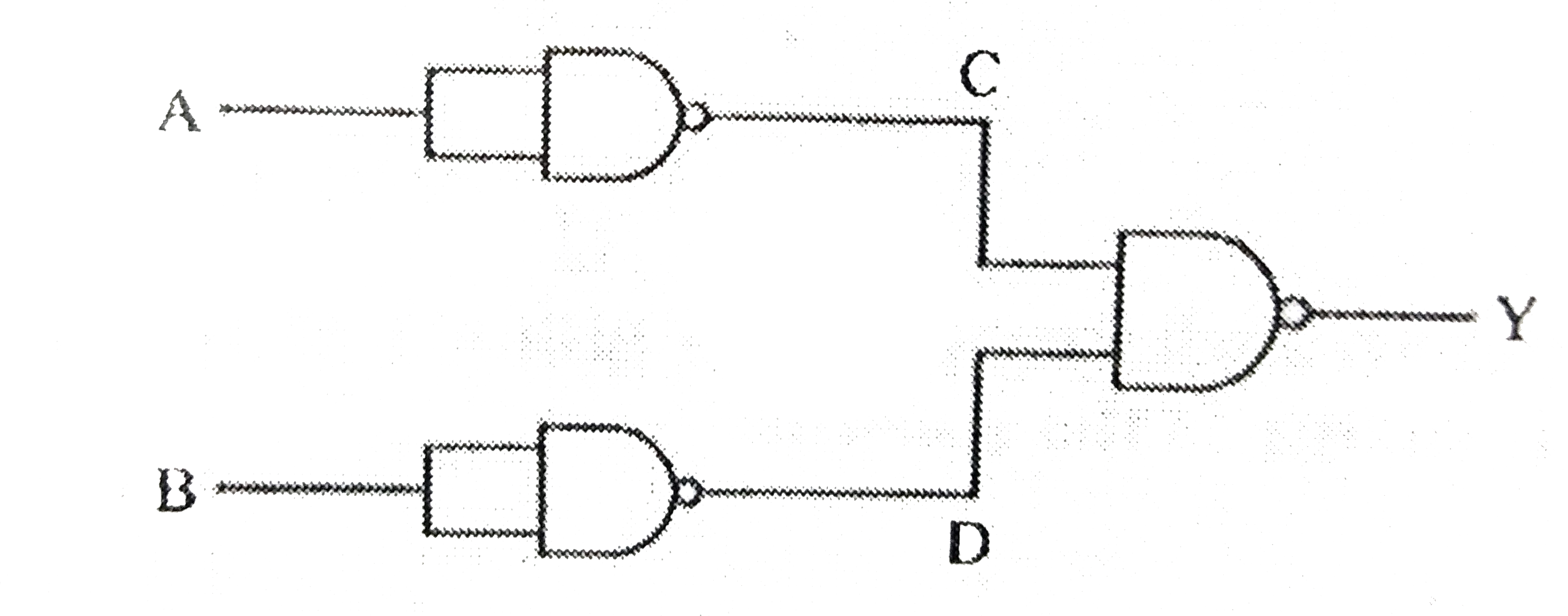
View SolutionWrite the truth table for the logic circuit shown below and identify the logic operation performed by circuit.
View SolutionWrite the truth table for the logic circuit shown below and identify the logic operation performed by circuit.

View Solutionनिचे चित्र में लॉजिक गेट का परिपथ एवं निवेशी तरंग रूप प्रदर्शित किया गया है
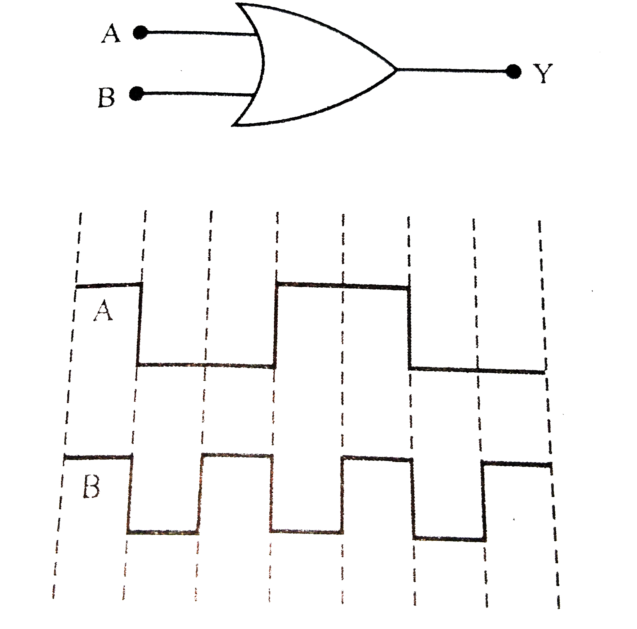
निर्गत तरंग रूप दीजिए |
View Solutionनीचे दर्शाये गये लॉजिक परिपथ के निवेश तरंग रूप A और B निम्न हैं। सही निर्गम का चयन कीजिए-
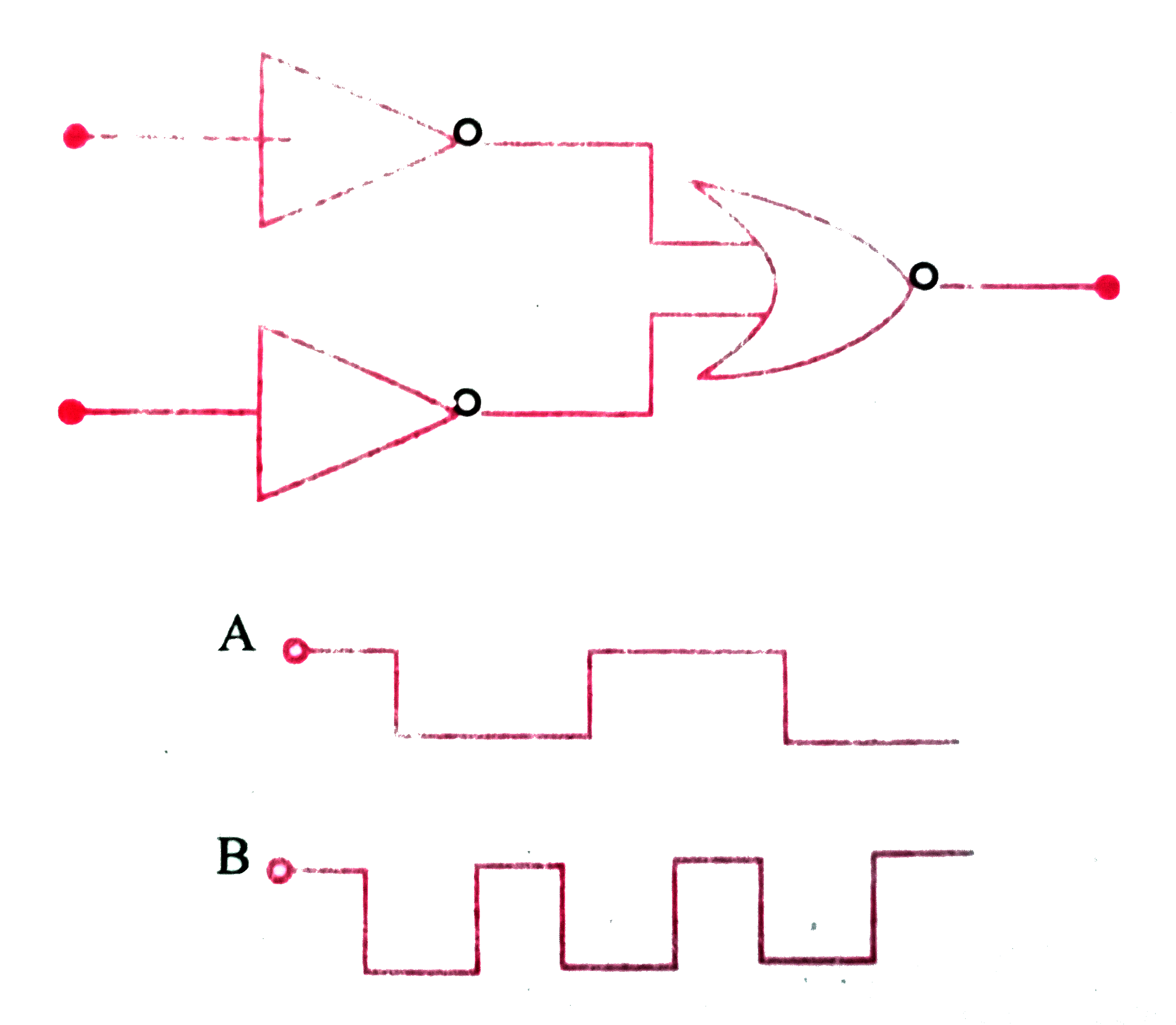
View SolutionFollowing are the input wave forms A and B of the logic circuit shown below. Choose the correct output Are issues
View SolutionFig, shows a logic gate circuit with two input A and B and the output C. The voltage wave form of A, B and C are as shown in Fig.The logic gate circuit is
View SolutionIdentify the logic operation performed by the circuit given here.
View SolutionIdentify the logic operation performed by the circuit given here.
View SolutionIdentify the logic operation performed by the circuit given here.
View SolutionThe given figure shows the wave forms for two inputs and and that for the output of a logic circuit.the logic circuit is
View Solution