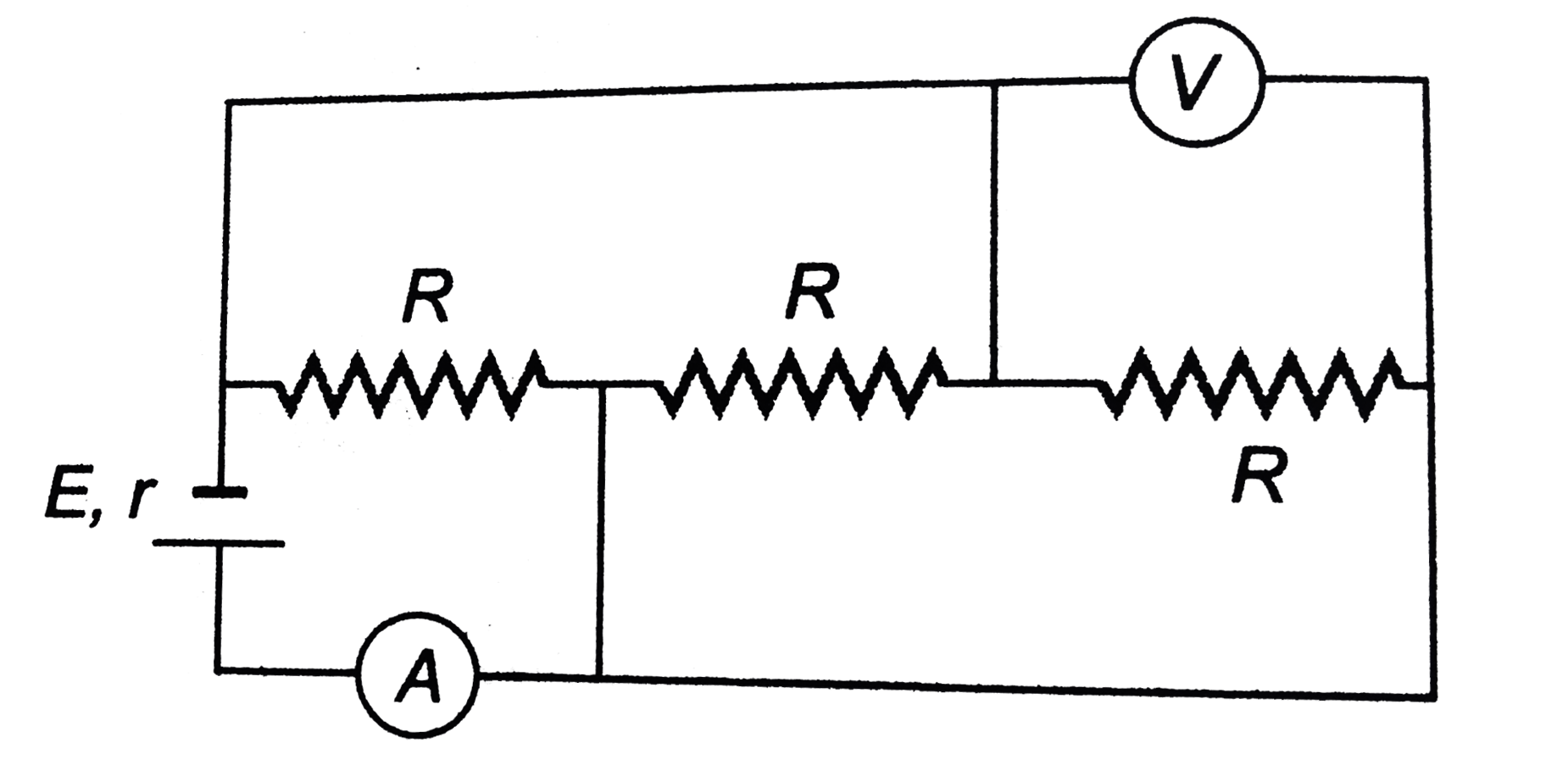
A perfect voltmeter and a perfect ammeter are connected in turn betweenpoints E and F of a circuit whose diagram is shown in Fig. 96. The readings of the instruments are U0 and I0.Determine the current I through the resistor of resistance R connected between points E and F.
We shall mentally connect in series two perfect having zero internal resistance current sources of emfs equal to -U6 . and U0 between points A and F. Obviously this will not introduce any change in the circuit. The dependence of the current through the resistor of resistance R on the emfs of the sources will have the formwhere ξ is the emf of the source contained in the circuit and the coefficients α and β depend on the resistance of the circuit.If we connect only one perfect source of emf equal to - U0 between A and F the potential difference between A and B will become zero. Therefore the first two terms in the equation for I will be compensated: I = βU0. The coefficient β is obviously equal to 1/R + Reff where Reff is the resistance between A and B when the resistor R is disconnected. This formula is also valid for the case R = 0 which corresponds to the connection of the ammeter. In this case Consequently the required current is
Related Solutions
When an ideal voltmeter is connected between the [points E and F the reading of the meter is V_(0) . When an ideal ammeter is connected between E and F, reading is I_(0) find the current I through resistor R connected between E and F.
View SolutionWhen an ideal voltmeter is connected between the points E and F (fig) the reading of the meter is . When an ideal ammeter is connected between E and F, readig is . Find the current I through a resistor R connected between E and F.
[Hint: The circuit behaves like voltage source of and some resistance r in series]View SolutionAn ammeter, a voltmeter and a resistor are connected in series to a cell and the readings are noted as I and V. If another resistor R is connected in parallel with the voltmeter, then:
View SolutionAn ammeter, voltmeter and a resistor are connected in series to a cell and the readings are noted as I and V. If another resistor R is connected in parallel with a voltmeter, then
View SolutionAn ammeter, voltmeter and a resistor are connected in series to a cell and the readings are noted as I and V. If another resistor R is connected in parallel with a voltmeter, then
View SolutionA voltmeter and an ammeter are connected in series to an ideal cell of . The voltmeter reading is , and the ammeter readings is . Then
(i) (ii) the voltmeter resistance is
(iii) the potential difference across the ammeter is
(iv) Voltmeter resistance + ammeter resistance = E//I
Correct statements areView SolutionA voltmeter and an ammeter are connected in series to an ideal cell of . The voltmeter reading is , and the ammeter readings is . Then
(i) (ii) the voltmeter resistance is
(iii) the potential difference across the ammeter is
(iv) Voltmeter resistance + ammeter resistance = E//I
Correct statements areView SolutionAn ammeter A, a voltmeter V and a resistance R are connected as shown in the figure. If the voltmeter reading is 1.6V and the ammeter reading is 0.4 A, then R is
View SolutionAn ammeter A, a voltmeter V and a resistance R are connected as shown in the figure. If the voltmeter reading is and the ammeter reading is A, then R is
 View Solution
A cell of emf E and internal resistance r is connected to two external resistance and a perfect ammeter. The current in the circuit is measured in four different situations :
(i) without any external resistance in the circuitView SolutionAn ammeter, voltimeter and a resistor are connected in series to a cell and the readings are noted as I and V. If another resistor R is connected in parallel with voltmeter, then
View SolutionA student connects a voltmeters, ammeter and resistance according to the circuit given. If the voltmeter reading is 20V and ammeter reading is 4A, then the resistance will be
 View Solution
A student connects a voltmeters, ammeter and resistance according to the circuit given. If the voltmeter reading is 20V and ammeter reading is 4A, then the resistance will be
 View Solution
A student connects a voltmeters, ammeter and resistance according to the circuit given. If the voltmeter reading is 20V and ammeter reading is 4A, then the resistance will be
 View Solution
An ammeter and a voltmeter are connected in series to an ideal battery of emf E. If the ammeter reads I and voltmeter reading V, then
View SolutionAn ammeter and a voltmeter are connected in series to an ideal battery of emf E. If the ammeter reads I and voltmeter reading V, then
View SolutionAn ammeter, a voltmeter V and a resistance R are connected as shown
 . Ameneter reads 2 A . Voltmeter reading is 10 V. Then R isView Solution
A battery of emf 2.5 V and internal resistance r is connected is series with a resistor of 45 ohm through an ammeter of resistance 1 ohm. The ammeter reads a current of 50 mA. Draw the circuit diagram and calculate the value of r.
View SolutionIn the circuit shown in figure ammeter and voltmeter are ideal. If and then readings of ammeter and voltmeter are
 View Solution
In the circuit shown in figure ammeter and voltmeter are ideal. If E=4 V,R=9Omega and r=1Omega then readings of ammeter and voltmeter are
View Solution
