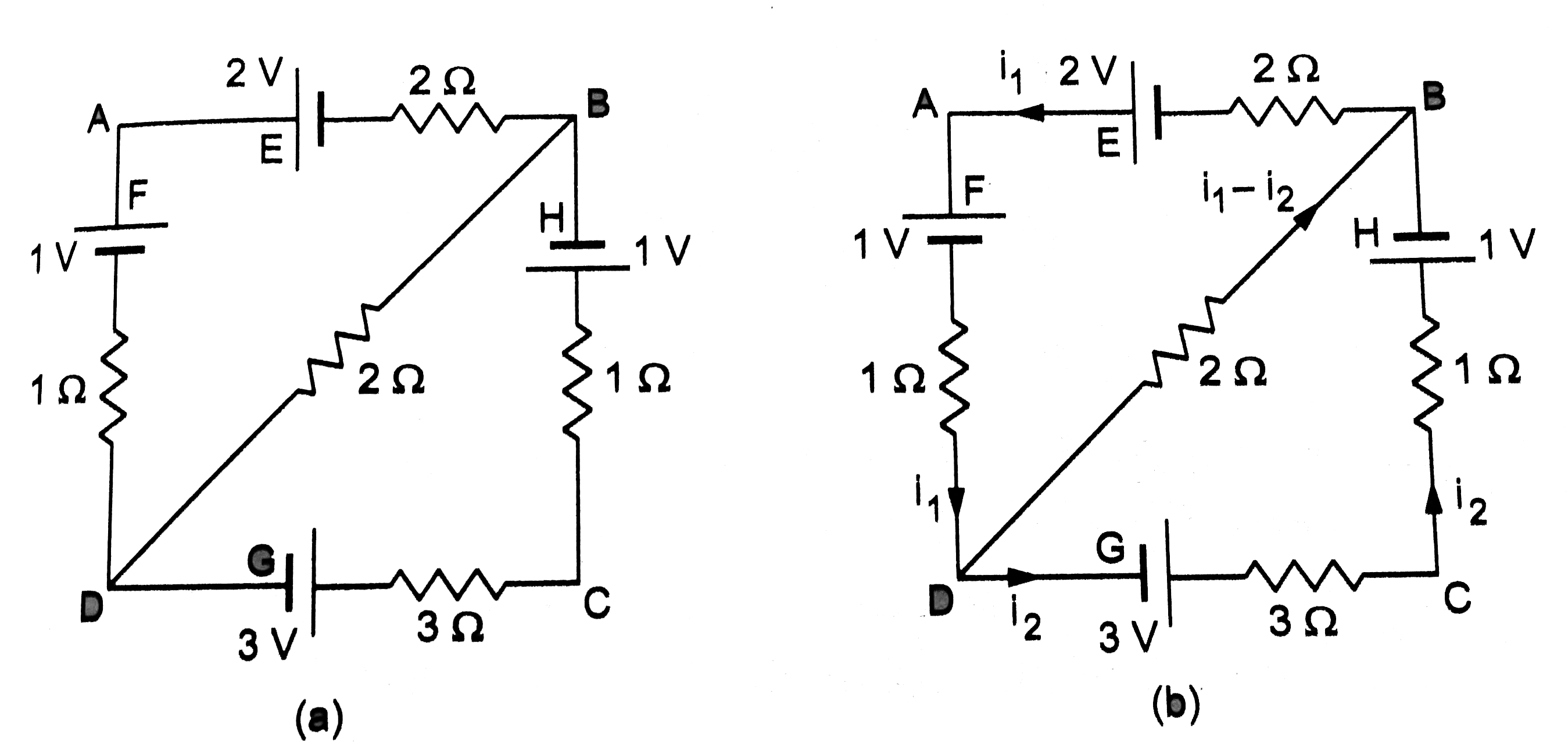
In the circuit shown in figure E,F, G and H are cell of emf 2,1,3, and 1V respectively. The resistances 2,1,3 and 1(Omega)are their respective internal resistance .Calculate (a)the potential difference between B and D and (b) the potential differences across the terminals of each of each of the cells G and H.
The correct Answer is:A, B, C
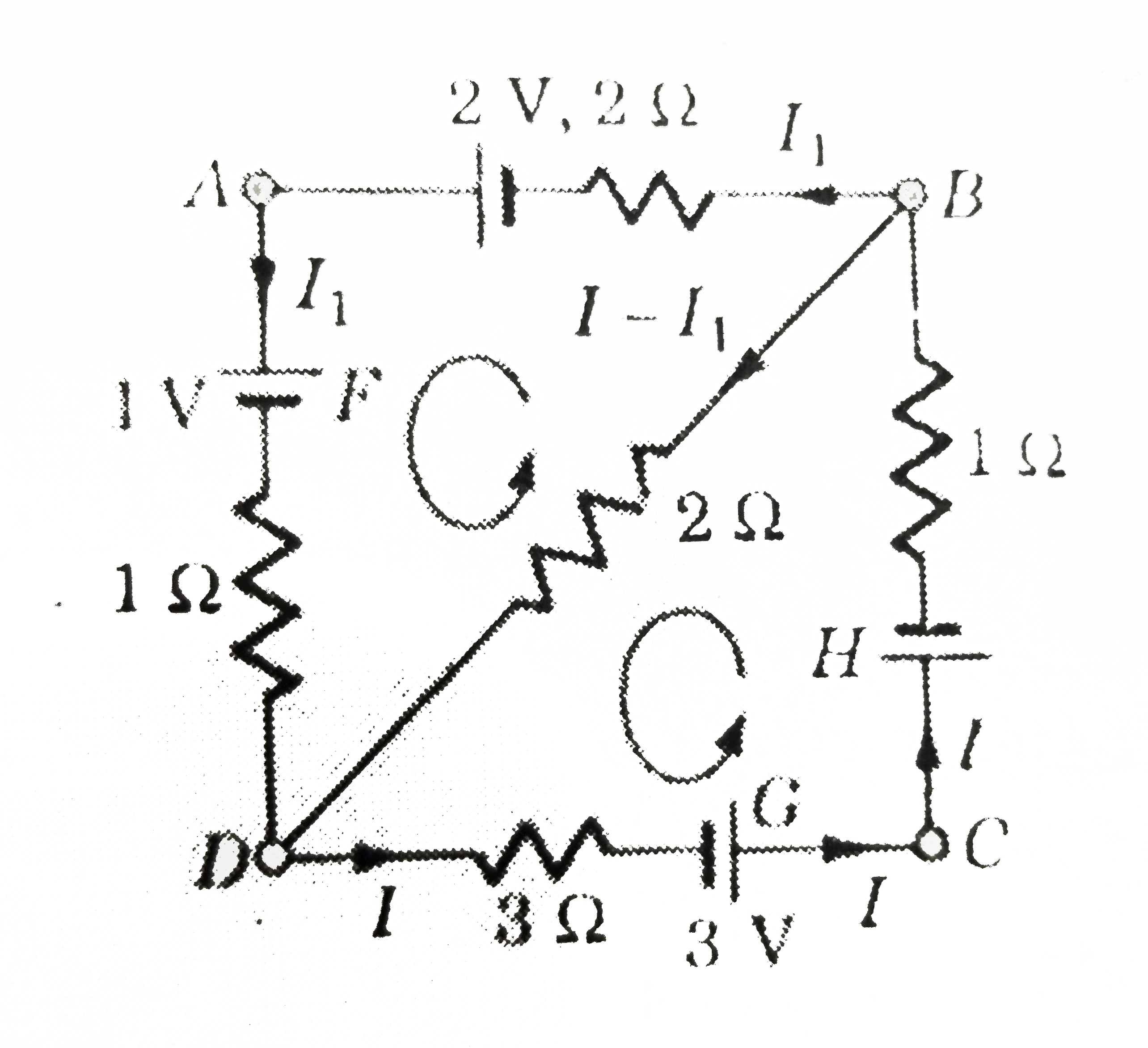
Let I2 current flow through the branch DCB
∴ByKirchoff'sjunctionlaw,current∈branchDBwillbe<br>I_2-I_1asshown∈figure.<br><imga≤ocr_imageload∈g=lazysrc=https://d10lpgp6xz60nq.cloudfront.net/physics_images/JMA_CE_C13_059_S01.pngwh=80%sty≤=background:white;><br>Apply∈gKirchoff'slaw∈l∞pBDAB<br>+2(I_2 - I_1) + 1 + 1 xx I_2 - 2 + 2I_2 = 0<br>rArr 2I_1 - 5I_2 = -1.........(i)<br>Apply∈gKirchoff'slaw∈l∞pBCDB,we≥t<br>-2 (I_2-I_1) + 1+I_1 -3 + 3I_1 = 0<br>rArr 3I_1 - I_2 = 1.........(ii)<br>Solv∈g(i)and(ii,we≥tI_1 = 6//13 amp<br>andI_2 = 5/13 amp<br>(i)Tof∈dthep.d.betweenBandD,wemoveomB→D.<br>V_(B) + [5/13 - 6/13] xx 2 = V_(D) :. V_(B)-B_(D) = 2/13 volt<br>(ii)p.d.acrossG = 3- 6/13 xx 3 = (39-18)/13 = 21/13 volt <br>[:. the cell is in discharging mode ] <br>p.d.acrossH=1+1×613=1913vo<
[∴cellis∈charg∈gmode] .
Topper's Solved these Questions
Similar Questions
In the circuit shown in E, F, G, and H are cells of emf 2,1,3 and 1 V, respectively. The resistances 2Ω,1Ω,3Ωand1Ω are their respectivle internal resistances.
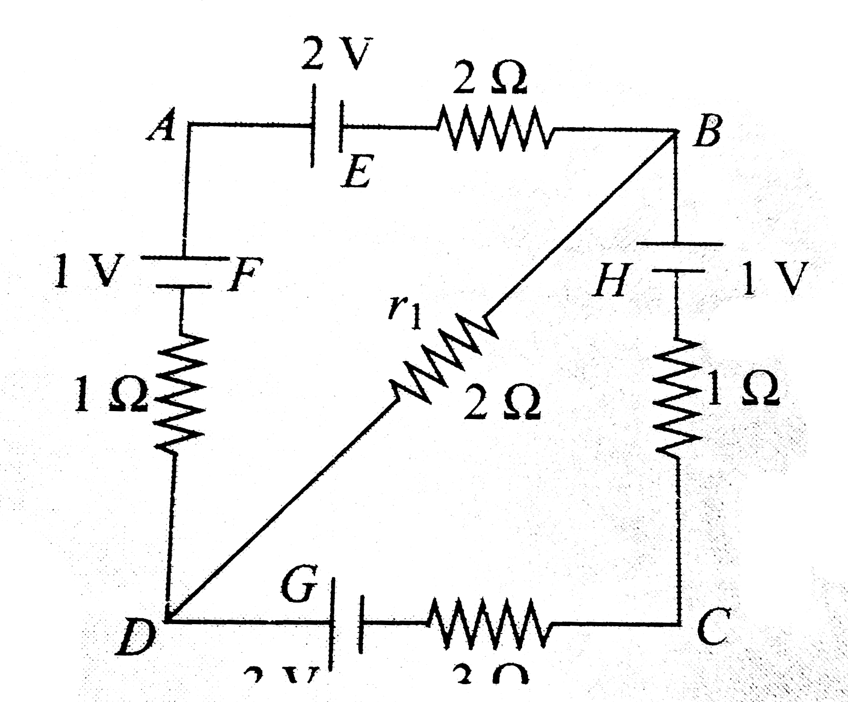
i. Find the potential difference between B and D.
(ii) Calculate the potential differences across the terminals of each of the cells G and H.
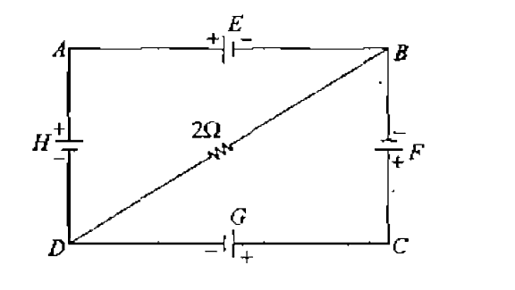
View SolutionIn the circuit shown in figure-3.159 cells E,F,G and H are of EMF 2V, 1V,3V and 1V respevitly and their internal resitance are 2Ω,1Ω,3Ω and 1Ω respectively Calculate
(a) The potential difference between points B and D
(d) The potential difference across the terminals of the cell G and H.
View Solution
Knowledge Check
In the circuit shown E,F,G and H are cells of emf 2V,1V,3V and 1V respectively and their internal resistance are 2Ω,1Ω,3Ω and 1Ω respectively.
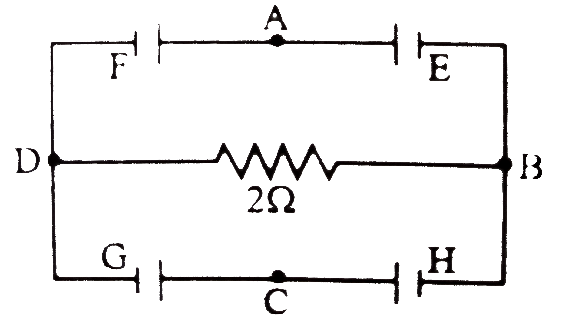 AVD−VB=−2/13VBVD−VB=2/13VCVG=21/13V=potential difference across GDVH=19/13V=potential difference across H
In the circuit E,F,G,Hare cell of emf 2,1,3and 1Ω respectively .The potential difference across the terminal of each of the cell G and H are
 A1.46V,1.61VB1.61V,1.46VC2.52V,1.61VD1.61V,2.25V
Two cells A and B of e.m.f.2 V and 1.5 V respectively, are connected as shown in figure through an external resistance 10 Ω The internal resistance of each cell is 5 Ω. The potential difference EAandEB across the terminals of the cells A and B respectively are
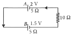 AEA=2.0v,EB=1.5VBEA=2.125V,EB=1.375VCEA=1.875V,EB=1.625VDEA=1.875V,EB=1.375V
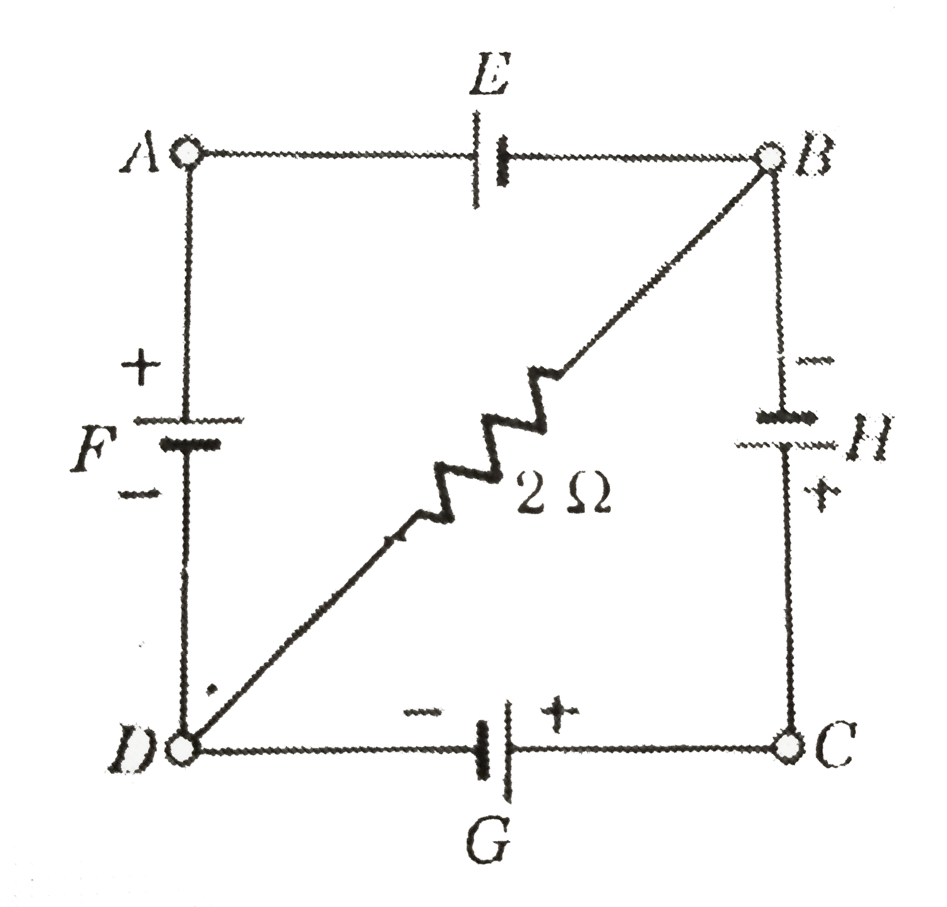
In the circuit shown in figure. The cells E,F,G and H have e.m.f's 2,1,3 and 1 V and internal resistance 2,1,3 and 1Ω respectively. Find the potential differences between points B and D, and across the terminals of the cells G and H.
View SolutionTwo non-ideal batteries have e.m.f 2V and 8V respectively and internal resistance 1 Omega and 2 Omega respectively as shown in the figure. If the potential difference between a and b is zero then the resistance R has a value
_PHY_E01_014_Q01.png)
View SolutionA cell of emf 'E' is connected across a resistance R.The potential difference between the terminals of the cell is found to be "V" .The internal resistance of the cell must be:
View Solutionv31
View SolutionA cell of e.mf. E and internal resistance r is connected in series with an external resistance nr. Then, the ratio of the terminal potential difference to E.M.F.is
View Solution