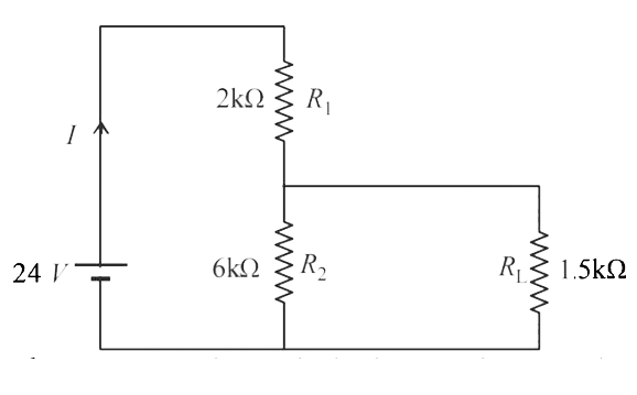
For the circuit shown in figure
A
the current I through the batter is 7.5 mA.
B
the potential difference across R_L is 18V.
C
ratio of powers dissipated in R1andR2 is 3
D
if R1andR2 are interchanged, magnitude of the power dissipated in RL will decrease by a factor of 9.
Video Solution
Text Solution
The correct Answer is:A, D
(a,d) 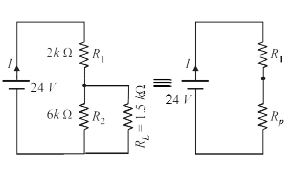
Rp=(R2×RLR2+RL)=6×1.56+1.5=97.5kΩ
∴I=⎛⎝2497.5+2⎞⎠mA=24×7.524=7.5mA.
⇒option(a)iscorrect.<br>Thepotentiald⇔erenceacrossR_L = potential<br>d⇔erenceacrossR_p<br>=(7.5mA)(9/7.5 kOmega) = 9V.<br>rArr option (b) is incorrect.
Now, (Power dissipation across R1)/(Power dissipation across R2) = ((15)22/(9)26)
=15×152×(69×9)=8.33
⇒option(c)is∈correct.<br>ThemagnitudeofpowerdissipatedarossR_2is<br>(9)^2. (1.5).
Now when R1andR2 are interchanged the equivalent
resistance between R1andRL=2×1.52+1.5=33.5kΩ
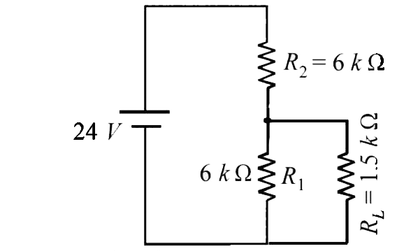
∴Potentialdropacrossthis≡a≤ntresistance.<br>((3/3.5)/(3/3.5 +6)) xx 24 = 3/24 xx 24 = 3V.<br>:. Potential difference accross RL=321.5=19[921.5]
∴Themagnitudeofthepowerdissipation∈R_Lwill<br>decreasebyafac→r9ifR_1 and R_2 are intercharged.
(d) is the correct option.
|
Topper's Solved these Questions
Similar Questions
Knowledge Check
In the circuit shown in figure
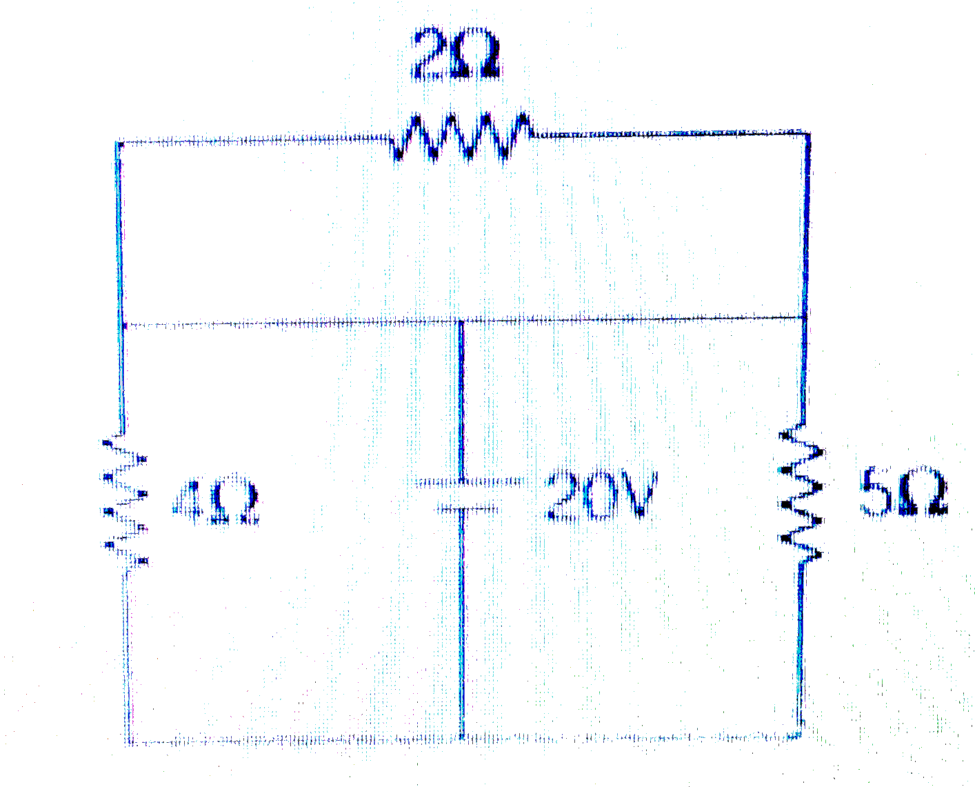 Acurrent passing through 2Ω resistance is zeroBcurrent passing through 4Ω resistance is 5 ACcurrent passing through 5Ω resistance is 4 ADAll of the above
In the circuit shown in figure
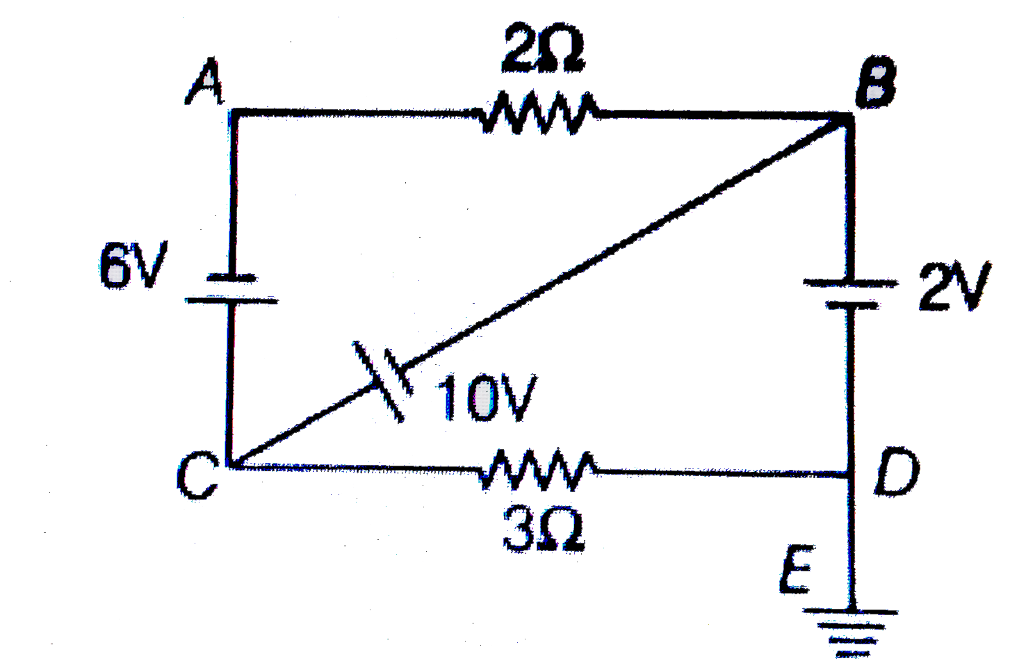 Acurrent passing through 2Ω resistance is 2 ABcurrent passing through 3Ω resistance is 4 ACcurrent in wire DE is zero.Dpotential of point A is 10 V
In the circuit shown in figure
 AE = 6.6 VBi1=1.1ACi2=0.5ADE = 4.4 V

