In the circuit shown in the figure, switch S is closed at time t=0. Select the correct statements.
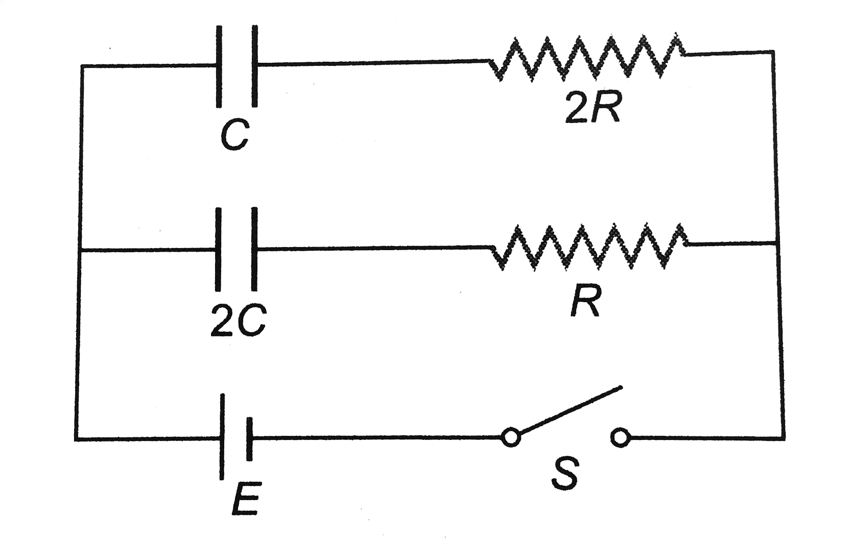
Rate of increase of charge is same in both the capacitors
Ratio of charge stored in capacitors C and 2C at any time t would be 1:2
Time constants of both the capacitors are equal
Steady state chares on capacitors C and 2C are in the ratio of 1:2
The correct Answer is:B, C, D
In steady, state,
qC=ECandq2C=2EC
τC=2CR of both circuits
At time t
qC=EC(1−etτC)
q2C=2EC(1−e−tτC)
∴qCq2C=12
Topper's Solved these Questions
- CAPACITORSBook:DC PANDEYChapter:CAPACITORSExercise:OBJECTIVE_TYPE
Explore 1 Video
- CAPACITORSBook:DC PANDEYChapter:CAPACITORSExercise:OBJECTIVE_TYPE
Explore 1 Video
- ATOMSBook:DC PANDEYChapter:ATOMSExercise:MEDICAL ENTRANCES GALLERY
Explore 42 Videos
- COMMUNICATION SYSTEMBook:DC PANDEYChapter:COMMUNICATION SYSTEMExercise:Subjective
Explore 11 Videos
Similar Questions
In the given circuit, the switch S is closed at time t=0 then select the correct statement for current l in resistance PQ as shown in the figure
_PHY_E05_091_Q01.png)
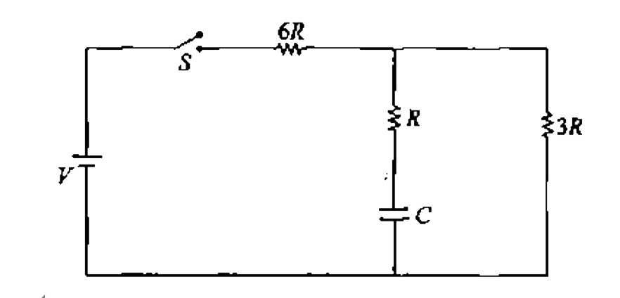
View SolutionIn the circuit shown in figure-3.240 switch S is closed at time t=0. find the current through different wires and charge stored on the capacitor at any time t.
View Solution
Knowledge Check
In the circuit as shown in the figure, switch S is added at t=0. Then:
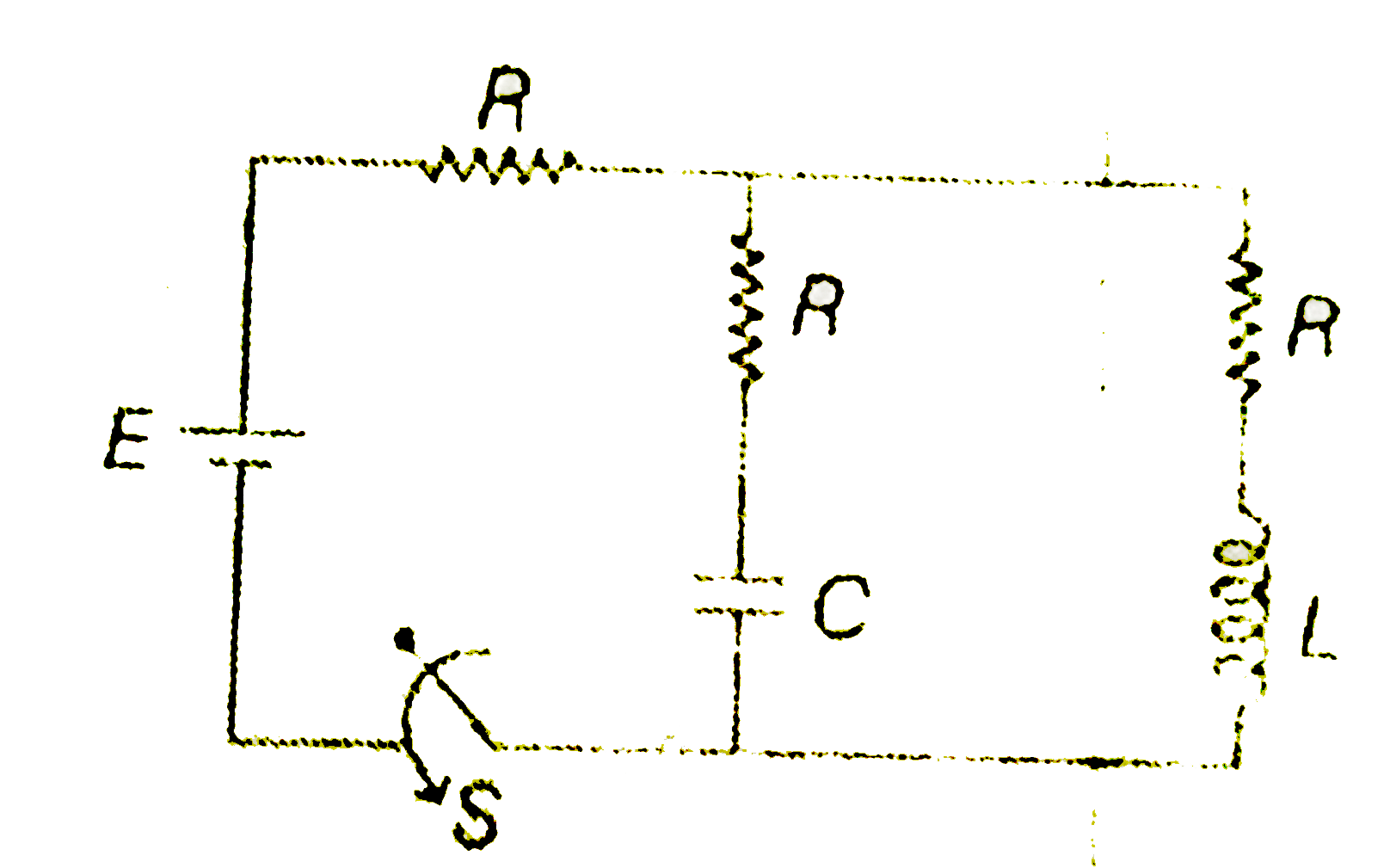 Aafter a long time interval potential differences across capacitor and inductor will be equalBafter a long time interval charge on a capacitor will be ECCafter a long time interval curent in the inductory will be E/RDafter a long time interval current through battery willl be same as the curren through it initially
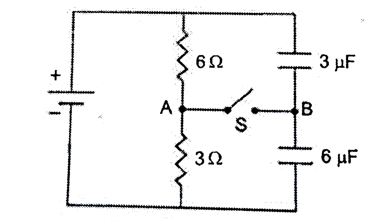
In the circuit shown above, when then switch S is closed,Ano charge flows through SBcharge flows from A to BCcharge flows from B to ADcharge flows initially from A to B and later from B to AIn the circuit shows in Fig the switch is closed at t=0.
 AAt t=0,I1=I2=0BAt any time t,I0I2=L2L1CAt any time t, I1+I2=εRDAt t=∞,I1 and I2 are independent of L1 and L2
In the given circuit, the switch S is closed at time t = 0, then select the correct statement for current l in resistance PQ as shown in the figure.
_PHY_E05_045_Q01.png)
View Solution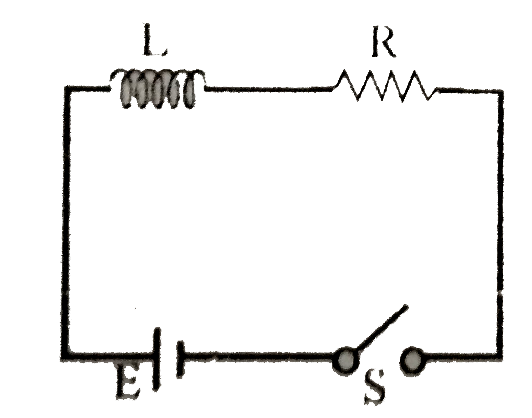
In the LR circuit as shown in figure, te switch is closed at t=0, mark the incorrect statement of the following
View SolutionIn the circuit shown in figure, circuit is closed at time t=0. At time t=ln(2) second
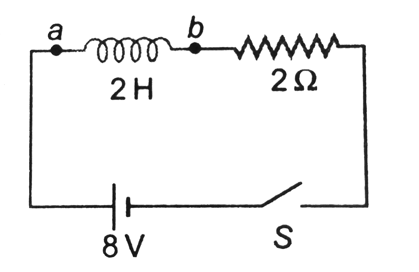
View SolutionIn the circuit shown in figure switch S is closed at time t=0
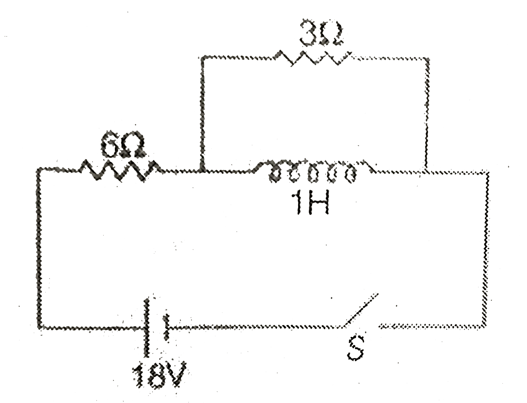
Takin left to right current through the indcutor as apositive current, current through inductor varies with time as
View SolutionIn the circuit shown in figure switch S is closed at time t=0
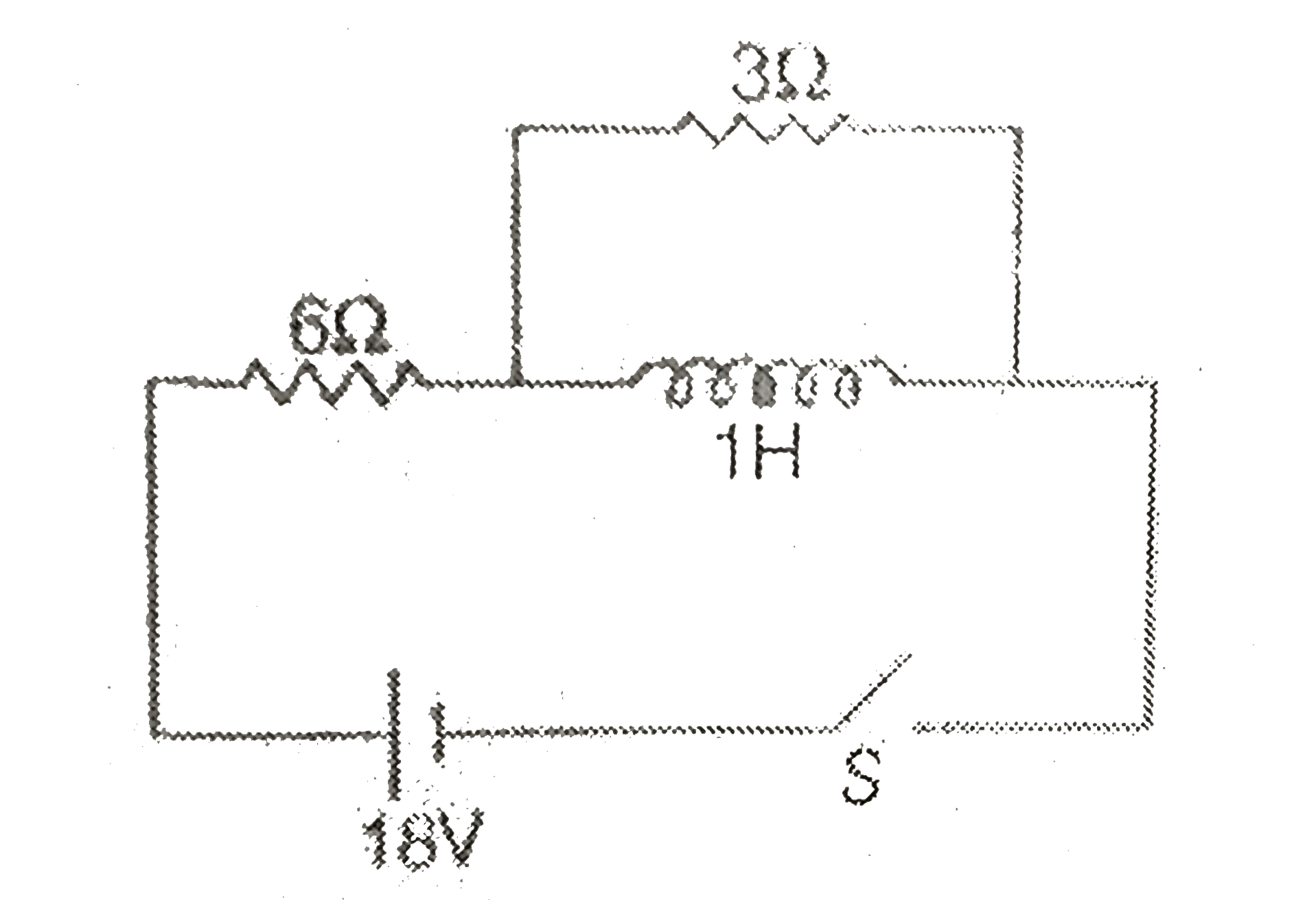
Current I from the battery at time t is given by
View Solution