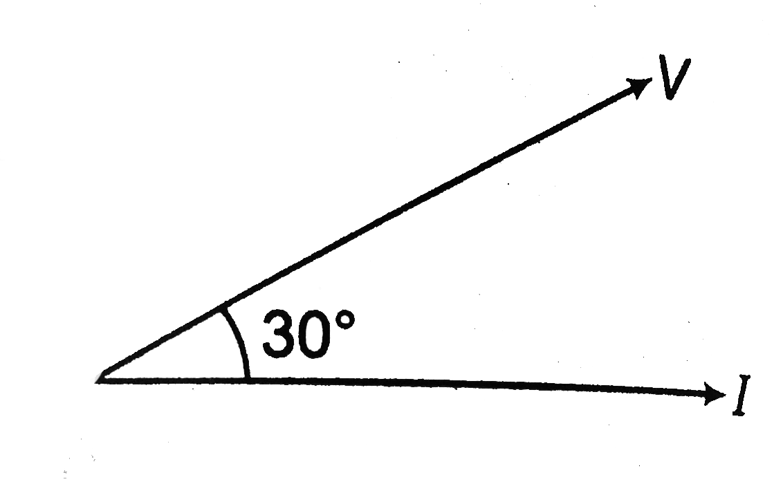
Draw the phasor diagram for a series RC circuit connected to an a.c. source.
The phasor diagram for a series RC circuit is shown in Fig. 7.18.

Topper's Solved these Questions
- ALTERNATING CURRENT BOOK - U-LIKE SERIESCHAPTER - ALTERNATING CURRENT EXERCISE - LONG ANSWER QUESTIONS -I
26 Videos
- ALTERNATING CURRENT BOOK - U-LIKE SERIESCHAPTER - ALTERNATING CURRENT EXERCISE - LONG ANSWER QUESTIONS -II
12 Videos
- ALTERNATING CURRENT BOOK - U-LIKE SERIESCHAPTER - ALTERNATING CURRENT EXERCISE - VERY SHORT ANSWER QUESTIONS
28 Videos
- ATOMSBOOK - U-LIKE SERIESCHAPTER - ATOMSEXERCISE - SELF ASSESSMENT TEST (SECTION C)
2 Videos
Similar Questions
(a) Draw graphs showing the variations of inductive reactnace and capacitive reactance with frequency of the applied ac source .
(b) Draw the phasor diagram for a series RC circuit connected to an ac source.
(c ) An alternating voltage of 220 V is applied across a device X , a current of 0.25 A flows , which lag behind the applied voltage in phase by π2 radian . If the same voltage is applied across another device Y , the same current flows but now it is in phase with the applied voltage .
(i) Name the devices X and Y.
(ii) Calculate the current flowing in the circuit when the same voltage is applied across the series combination of X and Y.

View SolutionDraw the phasor diagram for the devices X.
View Solution
Knowledge Check
Phasor diagram of a series AC circuit is shown in figure. Then,
 AThe circuit must be containing resistor and capacitor onlyBThe circuit must be containing resistor and inductor onlyCThe circuit must be containing all three elements L, C and RDThe circuit cannot have only capacitor and inductor
The impedance of a sereis RL circuit is same as the series RC circuit when connected to the same AC source separately keeping the same resistance. The frequency of the source is
A1√LCB12π√LCCRLD1RC
Draw the phasor diagram of a series LCR connected across an ac source V=V0sinωt. Hence derive the expression for the impedance of the circuit . Obtain the conditions for the phase angle under which the current is (i) maximum and (ii) minimum.
View SolutionDraw phase diagram for a series LCR circuit with alternating voltage source, determine the expression for the impedance of the circuit.
OR
Draw a diagram of AC generator and describe it.Derive an expression for instantaneous value of induced emf.
View SolutionWhat is a phasor diagram ? Draw a phasor diagram when a pure resistor is conneted acorss an a.c. supply and show that current and voltage are in the same phase.
View SolutionPhasor diagram of a series AC circuit is shown in figureure. Then,

View SolutionAn a.c. source, of voltage V=Vmsinωt , is applied across a series LCR circuit. Draw the phasor diagram for the circuit when the
(i) capacitive reactance exceeds the inductive reactance,
(ii) inductive reactance exceeds the capacitive reactance.
View SolutionPower dissipated in an L−C−R series circuit connected to an AC source of emf ε is
View Solution
